Table of Contents
Advertisement
Quick Links
Advertisement
Table of Contents

Subscribe to Our Youtube Channel
Related Manuals for TYAN Tank FT48 B5382


Summary of Contents for TYAN Tank FT48 B5382
- Page 1 Tank FT48 B5382 Service Engineer’s Manual...
- Page 3 TYAN retains the right to make changes to product descriptions and/or specifications at any time, without notice. In no event will TYAN be held liable for any direct or indirect, incidental or consequential damage, loss of use, loss of data or other problem resulting from errors or inaccuracies of information contained in this document.
-
Page 4: Federal Communications Commission
Federal Communications Commission Notice for the USA Compliance Information Statement (Declaration of Conformity Procedure) DoC FCC Part 15: This device complies with part 15 of the FCC Rules Operation is subject to the following conditions: 1) This device may not cause harmful interference, and 2) This device must accept any interference received including interference that may cause undesired operation. -
Page 5: About This Manual
About this Manual This manual provides you with instructions on installing your FT48- B5382, and consists of the following sections: Provides an Introduction to the FT48-B5382 bare- Chapter 1: bone, packing list, describes the external compo- nents, gives a table of key components, and provides block diagrams of the system. -
Page 6: Safety Information
Safety Information Before installing and using the FT48-B5382, take note of the following precautions: • Read all instructions carefully. • Do not place the unit on an unstable surface, cart, or stand. • Do not block the slots or openings on the unit which are provided for ventilation. -
Page 7: Table Of Contents
Table of Contents Chapter 1: Overview 1.1 About the TYAN Tank FT48-B5382 ........1 1.2 Product Model..............2 1.3 Features................3 1.4 Unpacking ................5 1.4.1 Box Contents ............... 5 1.4.2 Accessories ..............7 1.5 About the Product .............. 9 1.5.1 System Front View and Front Panel ...... - Page 8 3.2 Disassembly Flowchart ............ 45 3.3 Removing the Chassis Cover .......... 46 3.4 Removing the Front Door Assembly ........ 47 3.5 Replacing Motherboard Components ......48 3.5.1 Disconnecting All Motherboard Cables...... 48 3.5.2 Replacing the Motherboard ........49 3.6 Replacing the Cooling Fans..........50 3.7 Replacing the Fan Control Board........
-
Page 9: Chapter 1: Overview
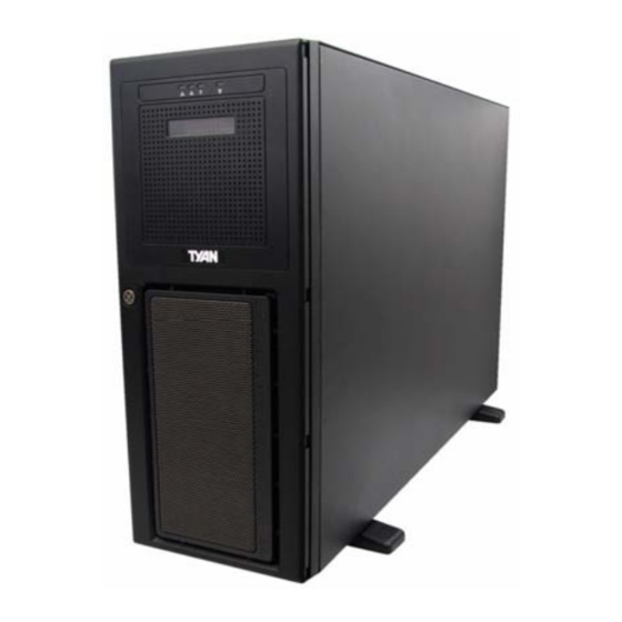
Chapter 1: Overview About the TYAN Tank FT48-B5382 Congratulations on your purchase of the TYAN Tank FT48- B5382, a highly-optimized tower or rack-mountable (option) barebone system. The TYAN Tank FT48-B5382 is ® ® designed to support the latest two Intel... -
Page 10: Product Model
Product Model Supported HDD Hot- Model Power supply type & quantity swappable B5382F48W8H SATA/SATA2 (8) 700W single PSU 750W (2+1) redundant, B5382F48W8HR SATA/SATA2 (8) hot swap PSU Chapter 1: Overview... -
Page 11: Features
• (1) PCI-E x16 slot (w/ x8 signals from MCH) Motherboard • (1) PCI-E x16 slot (w/ x8 signals from • TYAN Tempest i5000 PW (S5382) 6321ESB) • SSI/ Extended ATX footprint (12” x • (1) PCI slot 13”) •... - Page 12 2-pin chassis intrusion header • Multiple 4-pin fan monitoring headers • PECI circuit for “Woodcrest” and the processor thermal monitoring • Infineon SLB9635 Trusted Platform Module (TPM) • Tyan SMDC M3291, IPMI v2.0 compliant Remote server management kit (option) Chapter 1: Overview...
-
Page 13: Unpacking
1.4.1 Box Contents Component Description Industry standard 4U chassis with eight HDD bays and three further 5.25-inch device bays Tyan Tempest i5000PW S5382 mother- board (pre-installed) Two M5382 memory riser cards DVD-ROM drive (pre-installed) Two M1211 SAS/SATA backplanes (pre- installed) - Page 14 Component Description M1014 FAN control board (pre-installed) B5382FT48W8HR - 750W (2+1) redundant hot-swap PSU B5382FT48W8H - 700W single PSU (3) system cooling fans (pre-installed) 120 x 120 x 38 mm Chapter 1: Overview...
-
Page 15: Accessories
1.4.2 Accessories If any items are missing or appear damaged, contact your retailer or browse to TYAN’s Web site for service: http://www.tyan.com. The Web site also provides information on other TYAN products, plus FAQs, compatibility lists, BIOS settings, and more. - Page 16 FDD Cable HDD Screws FDD Front Panel Security Tab (including two screws) 1 x 1394 cable 1 x DVD-ROM cable Sliding Rail Kit (Option) 2 x Mounting Ears Rail assembly (including six screws) Screws & Small Brackets Chapter 1: Overview...
-
Page 17: About The Product
About the Product This section contains hardware diagrams and a block diagram of the FT48-B5382 system. 1.5.1 System Front View and Front Panel See the diagram below for details of the front panel indicators and switches. Power button USB ports Reset button LAN2 Power on... -
Page 18: System Rear View
1.5.2 System Rear View B5382F48W8H Stacked keyboard and mouse ports Power supply Security slot Serial port (COM 1) AC input VGA port USB ports Expansion slots From left to right: From top to bottom: Line-out, Line-in, Mic-in LAN1 port, LAN2 port LAN1 port On-board LAN0 LAN2 port... - Page 19 On the rear of the FT48-B5382, two screw holes are available for you to secure the chassis lid with two screws. By default, the unit has no screws secured from the rear. B5382F48W8HR AC input Security slot Redundant Power LED power supply Expansion slots...
-
Page 20: System Top View For Fan Leds
1.5.3 System Top View for FAN LEDs FAN3 LED FAN2 LED FAN1 LED Color Description FAN1/FAN2/FAN3 Green Fan is functioning normally. Fan fails. 1.5.4 LED Control Panel Color State Description Power LED System is turned on No mains power HDD/ IDE Green Blinking Internal SATA/ IDE access... -
Page 21: Hdd Tray Leds
1.5.5 HDD Tray LEDs Color State Description Hot Swappable HDD Green Power connected Power/ Access LED (Only for internal SAS Green Blinking SATAII/ SAS HDD access port access) activity Power disconnected Hot Swappable HDD Amber SAS HDD fail (reserved SAS Fail LED for SAS add-on card) No failure found 1.5.6 Rear LEDs... -
Page 22: Motherboard Layout
1.5.7 Motherboard Layout Chapter 1: Overview... -
Page 23: Jumpers & Connectors
1.5.8 Jumpers & Connectors Jumper/Connector Function Audio Front Panel Header SMDC CON25 x 2_M3291 IPMB Pin Header COM PORT Pin Header J91/J96 IEEE 1394a Pin Header JP16 Front Panel Header USB Header (5-Pin x 1) USB Header (5-Pin x 2) P12/P13/P92/P8/P9 Fan Connectors (4-Pin x 1) CD-IN (4-Pin x 1) -
Page 24: B5382 System Block Diagram
1.5.9 B5382 System Block Diagram Chapter 1: Overview... -
Page 25: 10System Internal View
1.5.10 System Internal View 1. Memory riser cards 7. Floppy disk drive socket 2. CPU0 / CPU 1 sockets 8. IDE socket (DVD-ROM drive) 3. System fans 9. SAS/SATA backplane 1 (Right to left): FAN1/2/3 10. SAS/SATA backplane 2 4. Cradle for 5.25-inch devices 11. - Page 26 Chapter 1: Overview...
-
Page 27: Chapter 2: Setting Up
Chapter 2: Chapter 2: Setting Up Before You Begin This chapter explains how to install motherboard compo- nents, including CPUs, CPU heatsinks, memory modules, and PCI cards. There are also instructions in this section for installing SATA hard drives. Take note of the precautions mentioned in this section when installing your system. -
Page 28: Precautions
2.1.3 Precautions Components and electronic circuit boards can be damaged by discharges of static electricity. Working on a system that is connected to a power supply can be extremely dangerous. Follow the guidelines below to avoid damage to the Tank FT48-B5382 or injury to yourself. -
Page 29: Installing Motherboard Components
Installing Motherboard Components This section describes how to install components on to the motherboard, including CPUs, memory modules and expan- sion cards. 2.2.1 Removing the Chassis Cover Follow these instructions to remove the Tank FT48-B5382 chassis cover. This step is required before any other proce- dures in this chapter can be undertaken. -
Page 30: Installing The Cpus And Heatsinks
2.2.2 Installing the CPUs and Heatsinks This section describes how to install Intel Xeon processors and heatsinks on the FT48-B5382 motherboard. 1. Locate the two CPU sockets on the motherboard. 2. Take off the CPU protection cap. 3. Pull the CPU lever up to unlock the CPU socket. Chapter 2: Setting Up... - Page 31 4. Open the socket in the direction as illustrated. 5. Place the CPU in the socket as shown, making sure that pin 1 is located correctly. NOTE: The CPU will only fit in the socket one way. No force should be required to insert the CPU. 6.
- Page 32 7. Remove all packaging from the new heatsink. Place the fan and heatsink on top of the CPU and attach with four screws as shown. NOTE: All heatsinks must be installed with fans facing the rear of the chassis to ensure efficient cooling. 8.
-
Page 33: Installing The Memory
2.2.3 Installing the Memory Follow the instructions in this section to install memory mod- ules in your FT48-B5382 system. 1. Locate the memory sockets on the memory riser cards. 2. Rotate the four press brackets as shown to release the memory riser card. - Page 34 4. Press the memory slot locking levers in the direction of the arrows as shown. 5. Insert the memory module into the slot. NOTE: Memory modules will fit in the slot only one way. Ensure that the notches in the memory modules line up with the corresponding notches in the slots.
- Page 35 6. Insert the two memory riser cards into the socket as shown. 7. Install the four supplied press brackets in the direction of the arrow shown to fix the memory riser card. 8. Fasten the four press bracket screws as shown until firmly secured.
- Page 36 M5382 Layout Attention When Installing the Memory! Refer to the following table for supported memory populations. Quantity of memory installed DIMM1 DIMM2 DIMM3 Fully Buffered DIMM4 DIMM Riser DIMM5 Socket 0 DIMM6 DIMM7 DIMM8 DIMM1 DIMM2 DIMM3 Fully Buffered DIMM4 DIMM Riser DIMM5 Socket 1...
-
Page 37: Installing The Pci/Pci-X/Pci-E Cards
2.2.4 Installing the PCI/PCI-X/PCI-E Cards The FT48-B5382 has seven expansion slots: 4 x PCI-X slots 2 x PCI-E x16 slots 1 x PCI slot Follow the instructions in this section to install a PCI card in your system. 1. Locate the PCI/PCI-X/PCI-E card slots on the mother- board. - Page 38 3. Lift up the blanking plate. 4. Insert a PCI/PCI-X/PCI-E card into a spare slot as shown, making sure it is firmly seated. 5. Secure the PCI/PCI-X/PCI-E card with the screw you removed from the blanking plate. Chapter 2: Setting Up...
-
Page 39: Installing Hard Drives
Installing Hard Drives The FT48-B5382 supports eight, hot-swappable SAS/SATA hard drives. The unit is shipped with eight hot-swap bays and two SATA backplanes. Hotswap HDD bays (Bottom to top: HDD1, HDD2, HDD3, HDD4, HDD5, HDD6, HDD7, HDD8) Chapter 2: Setting Up... - Page 40 Follow these instructions to install a hard drive. 1. Press the release clip (A) and pull the release lever up to unlock the drive tray from the chassis (B). 2. Pull the empty drive tray from the chassis. 3. Place a SAS/SATA hard drive in the drive tray. Chapter 2: Setting Up...
- Page 41 4. Secure the hard drive in place using four HDD screws. 5. Insert the drive tray back into the chassis and push the locking lever into place to secure it. Chapter 2: Setting Up...
-
Page 42: Installing The Second Dvd-Rom (Option)
Installing the Second DVD-ROM (Option) Follow these instructions to install the second DVD-ROM. 1. Remove the FAN1 and FAN2 in the direction of the arrow from the chassis. 2. Unfasten an empty drive bracket from the chassis in the direction of the arrow shown. 3. - Page 43 4. Attach the two rails removed from the drive bracket to the DVD-ROM with eight screws. 5. Slide the DVD-ROM into the chassis. 6. Connect the power and DVD-ROM cables to the rear of the DVD-ROM drive. Chapter 2: Setting Up...
-
Page 44: Installing The Floppy Disk Drive (Option)
Installing the Floppy Disk Drive (Option) Follow these instructions to install a floppy disk drive. 1. Remove all the fans in the direction of the arrow from the chassis. 2. Remove the two screws securing the fan cradle to the chassis. - Page 45 4. Unfasten an empty drive bracket from the chassis in the direction of the arrow shown. 5. Use a thin tool such as a flat screwdriver to pry open the front panel of the drive bracket as indicated. 6. Remove the front panel and the inner piece as shown. Chapter 2: Setting Up...
- Page 46 7. Install the FDD front panel to the front of the bracket. 8. Place a FDD in the drive bracket. 9. Secure the FDD in place using four screws. Chapter 2: Setting Up...
- Page 47 10. Slide the FDD with the drive bracket back into the chassis. 11. Connect one end of the supplied FDD cable and the power cable to the rear of the FDD (A). Pass the other end through the space behind the metal plate as shown below (B).
-
Page 48: Installing Chassis Foot Stands
Installing Chassis Foot Stands The FT48-B5382 can be used as a standalone device when fitted with the supplied plastic feet. When used as a standal- one device, the feet must be fitted to prevent the unit from falling over. The four feet should be attached as follows: 1. -
Page 49: Opening The Chassis Door
Opening the Chassis Door 1. Insert the front door key (packed in a bag in the acces- sory box) and rotate the key 90 degrees counterclock- wise to unlock the door. 2. Pull the door in the direction of the arrow to open. Chapter 2: Setting Up... -
Page 50: Installing The Security Tab
Installing the Security Tab 1. Insert the supplied security tab into the security slot from the rear of the FT48-B5382 as shown below. 2. Secure the security tab with two screws. 3. Now you can lock the FT48-B5382 chassis with a padlock using the opening from the security tab. -
Page 51: Chapter 3: Replacing Pre-Installed Components
Chapter 3: Replacing Pre-installed Components Introduction This chapter describes how to replace all the pre-installed components of your FT48-B5382, including the motherboard, SATA backplane, LED control board, power supply, cooling fans, and fan control board. Take note of the precautions in this section when installing your system. -
Page 52: Precautions
3.1.3 Precautions Components and electronic circuit boards can be damaged by static electricity. Working on a system that is connected to a power supply can be extremely dangerous. Follow the guidelines below to avoid damage to the FT48-B5382 or injury to yourself. •... -
Page 53: Disassembly Flowchart
Disassembly Flowchart The following flowchart outlines the disassembly procedure. Rear Components DIMMs Single/ Redundant power Chassis top cover Heatsink/CPU assembly Mainboard PCI card Mainboard Front Components Chassis top cover PCBs DVD-ROM Control Board Fan Board HDD Board The Transport FT48-B5382 should be always Note: powered off before disassembly. -
Page 54: Removing The Chassis Cover
Removing the Chassis Cover Follow these instructions to remove the Tank FT48-B5382 chassis cover. This step is required before any other proce- dures in this chapter can be undertaken. 1. Press the button on the release catch and lift the catch. Slide the chassis lid back slightly. -
Page 55: Removing The Front Door Assembly
Removing the Front Door Assembly A door is supplied with the FT48-B5382 that can be used when the unit is rack mounted or standalone. Follow these instructions to remove the door. 1. Pull out the four fixing bars locking the door assembly onto the server. -
Page 56: Replacing Motherboard Components
Replacing Motherboard Components Follow these instructions to remove motherboard components and replace the motherboard. 3.5.1 Disconnecting All Motherboard Cables Before replacing the motherboard or certain components, remove cables connected to the motherboard. Follow these instructions to remove all motherboard cabling. 1. -
Page 57: Replacing The Motherboard
3. Disconnect the fan cables. 3.5.2 Replacing the Motherboard After removing all of those cables, follow these instructions to replace the motherboard in your FT48-B5382. 1. Remove the heatsinks and processors if installed. 2. Remove the nine screws securing the motherboard to the chassis. -
Page 58: Replacing The Cooling Fans
Replacing the Cooling Fans The FT48-B5382 requires three chassis cooling fans. Follow these instructions to replace a cooling fan. 1. Remove the fan in the direction of the arrow from the chassis. 2. Replace a new fan into the fan cradle following the above steps in reverse. -
Page 59: Replacing The Fan Control Board
Replacing the Fan Control Board To replace the fan control board, you need to remove all the fans and the fan cradle first. Refer to the first three steps given in “2.5 Installing the Floppy Disk Drive (Option)”. Then, do the following: 1. - Page 60 4. Remove the two screws securing the fixing brackets to the fan control board. 5. Remove the two fixing brackets as instructed for replacement of the fan control board. 6. Remove the ten screws securing the fan board to the chassis.
-
Page 61: Fan Board Features
3.7.1 Fan Board Features FAN2 FAN1 Connector Connector J3 PWM Header J2 Big 4P Power Connector J1 Big 4P Power Connector FAN4 FAN3 Connector Connector FAN5 FAN6 Connector Connector Chapter 3: Replacing Pre-installed Components... -
Page 62: Fan Board Connector Pin Definition
3.7.2 Fan Board Connector Pin Definition J3 and PWM Pin Header FAN1 PWM FAN2 PWM FAN3 PWM FAN4 PWM FAN5 PWM FAN5 PWM FAN PWM INPUT KEY PIN MUTE+ FAN1~FAN6 Fan Connector Pin Out VDD +12V CLOCK J1, J2 Big 4-pin Power Connector Pin Out VDD +12V VDD +5V Each system fan connects to the fan board as listed below:... -
Page 63: Replacing The Sas/Sata Backplane
Replacing the SAS/SATA Backplane To replace the SAS/SATA backplane, you need to remove all the fans and the fan cradle first. Refer to the first three steps given in “2.5 Installing the Floppy Disk Drive (Option)”. Then, do the following: 1. -
Page 64: M1211 Sas/Sata Backplane Features
3.8.1 M1211 SAS/SATA Backplane Features Front View (Top to bottom) J1/J2/J3/J4 29 pin SAS/SATA connectors Rear View JP3 2x4 pin header for SAS J13/J14 Big 4P Hard Disk Failure LED Power Connector (Top to bottom) J5/J6/J7/J8 (Default) Primary 7 pin connectors (Top to bottom) J9/J10/J11/J12 (SAS solution only) Secondary 7 pin connectors Chapter 3: Replacing Pre-installed Components... -
Page 65: M1211 Sas/Sata Backplane Connector Pin Definition
3.8.2 M1211 SAS/SATA Backplane Connector Pin Definition For Hard Disk Fail LED Input HDD AF+ HDD AF- HDD BF+ HDD BF- HDD CF+ HDD CF- HDD DF+ HDD DF- J13 and J14 Big 4-pin Power Connector Pin Out VDD +12V VCC +5V Chapter 3: Replacing Pre-installed Components... -
Page 66: Replacing The Led Control Board
Replacing the LED Control Board Follow these instructions to replace the LED control board. 1. Remove the FAN1 in the direction of the arrow from the chassis. 2. Remove all the cables from the LED control board. 3. Unfasten the LED module and slide it out as shown to lift it free of the chassis. - Page 67 4. Remove the three screws securing the LED control board to the bracket. 5. Slide the LED control board from the bracket as shown. 6. After replacement, insert and secure the unit to the chassis following the above steps in reverse. Chapter 3: Replacing Pre-installed Components...
-
Page 68: M1007 Led Control Board Features
3.9.1 M1007 LED Control Board Features J1 2x5 pin USB Header USB1 USB2 Reserved Function Power LED Reserved Function HDD Access LED LAN1 LED LAN2 LED J2 2x14 pin Header Reserved Function Reserved Function Reset Switch Power Switch Chapter 3: Replacing Pre-installed Components... -
Page 69: M1007 Led Control Board Connector Pin Definition
3.9.2 M1007 LED Control Board Connector Pin Definition J1 2 x 5 Pin USB Header VCC +5V VCC +5V USB1- USB0- USB1+ USB0+ KEY PIN J2 2 x 14 Pin Connector HD_LED+ HD_LED- RESET+ RESET- PW_LED+ PW_LED- WLED+ WLED - ICH_SMBDAT ICH_SMBCLK EXT_INT... -
Page 70: Replacing The Dvd-Rom
3.10 Replacing the DVD-ROM Follow these instructions to replace the DVD-ROM. 1. Remove the FAN1 and FAN2 in the direction of the arrow from the chassis. 1. Remove the power and DVD-ROM cables from the rear of the DVD-ROM drive. 2. - Page 71 3. Remove the eight screws securing the two DVD-ROM rails to the drive. 4. After replacement, insert the unit to the chassis following the above steps in reverse. Chapter 3: Replacing Pre-installed Components...
-
Page 72: Replacing The Power Supply
3.11 Replacing the Power Supply 3.11.1 Standard Power Supply To replace the power supply follow these instructions. 1. Unplug the power cable from the faulty power supply. 2. Remove the three screws that secure the power supply to the chassis. 3. -
Page 73: 2Redundant Power Supply
5. Pull out the power supply unit from its casing. 6. Remove the four screws securing the cover plate to the power supply unit. 7. After replacement, place and secure the unit into the chassis following the above steps in reverse. 3.11.2 Redundant Power Supply If the 2+1 redundant power supply is fitted, any of the three units can be hot swapped. - Page 74 2. Release the redundant power supply by turning thumb screw clockwise. 3. Press the latch and the handle together as shown. 4. Pull out the power supply unit as shown. 5. Place the unit with the new power supply unit and secure by tightening the thumb screw.
-
Page 75: Appendix I: Bios Differences
Appendix I: BIOS Differences The BIOS of B5382 is similar to the BIOS of S5382. There is only one menu different. You may refer to the attached motherboard manual for the complete BIOS information. The differences between B5382 and S5382 is on the “Advanced/Hardware Health Information”... -
Page 76: Hardware Monitor
S5382 Advanced/Hardware Monitor Information PhoenixBIOS Setup Utility Advanced Item Specific Help Fan Speed Control: [Full Speed] Cpu Temp Reading: [PECI] Select mode to Front Fan 3pin/4pin [4pin] control fan speed. Rear Fan 3pin/4pin [4pin] Realtime sensors Help Select Item Change Values Setup Defaults Exit Select Menu... -
Page 77: Appendix Ii: Cable Connection Tables
Appendix II: Cable Connection Tables SAS/SATA Cables Table 1: FT48-B5382 Model M1211 SAS/SATA Connects to Motherboard Backplane 1 J8 (HDD1) SAS1 J7 (HDD2) SAS2 J6 (HDD3) SAS3 J5 (HDD4) SAS4 M1211 SAS/SATA Connects to Motherboard Backplane 2 J8 (HDD5) J7 (HDD6) SAS5~8 J6 (HDD7) J5 (HDD8) - Page 78 Table 3: Power Supply to Motherboard P2 8-pin power cable PWR2 8-pin connector P3 8-pin power cable PWR3 8-pin connector Table 4: Power Supply to Backplane M1211 SAS/SATA Power Supply Connects to Backplane 1 P9 4-pin power cable P8 4-pin power cable M1211 SAS/SATA Power Supply Connects to...
- Page 79 Other Cables Table 8: LED Control Board to Motherboard LED Control Board Connects to Motherboard USB connector JP16 Front panel header JP31, JP32 Table 9: DVD-ROM Cable to Motherboard DVD-ROM Connects to Motherboard DVD-ROM 1 DVD-ROM 2 (option) Table 10: FDD Cable to Motherboard (Option) Connects to Motherboard FDD drive...
-
Page 80: Appendix Iii: Installing The Smdc Card (Option)
Appendix III: Installing the SMDC Card (Option) The following provides you with the information on installing M3291 SMDC card into any PCI slot in your FT48-B5382 sys- tem. 1. Secure M3291 on a PCI bracket as shown. 2. Connect the following cables to M3291 as shown. a. - Page 81 4. Lift up the blanking plate. 5. Connect the other end of SMDC cable and serial cable to the SMDC connector (J79) and COM header (J88) on the motherboard. 6. Place the SMDC card in the PCI slot as shown.
- Page 82 7. Secure the PCI bracket with the screw you removed from the blanking plate. Cable Connection Table SMDC Card (M3291) Connects to Motherboard J1 connector J79 SMDC connector J88 COM port pin J2 COM port header...
-
Page 83: Appendix Iv: Rack Mounting (Option)
Appendix IV: Rack Mounting (Option) Installing the 5.25” Devices in Rackmount Position Before mounting the FT48-B5382 in a rack, you need to rotate all the drives to the rackmount position first. Follow the steps as instructed below. 1. Remove all the fans and the fan cradle first. Refer to the first three steps given in “2.5 Installing the Floppy Disk Drive (Option)”. - Page 84 4. Slide all the drives or the brackets out of the chassis. 5. Slide all the drives or the brackets back into the chassis vertically. 6. Replace all the cables to the devices as shown.
- Page 85 7. Remove the front bezel from the door assembly and rotate it 90 degrees counterclockwise as shown. 8. Fit the front bezel back into position. 9. Now, all the drives and the front bezel are in the rackmount position.
-
Page 86: Installing The Server In A Rack
Installing the Server in a Rack The Tank FT48-B5382 can either be set in a tower position using the supplied chassis foot stands or mounted in a stan- dard rack using the sliding rail kit. Sliding rail kit (Option) Rail assembly x 2 Mounting Ears x 2 Screws Kit x 3 Follow these instructions to mount the FT48-B5382 into an... - Page 87 Installing the Inner Rails to the Unit 1. Remove the black panels from the left and right sides of server to reveal the rail mounting screwholes beneath. 2. Screw the mounting ears to each side of the FT48-B5382 as shown using three M4-L5 screws (C) from the supplied screws kit.
- Page 88 Installing the Outer Rails to the Rack 4. Measure the distance between inner side of the front and rear mounting brackets in the rack. 5. Adjust the outer rails to fit the length of the rack (the distance measured in step 4). The sliding brackets have long slits to allow them to be fixed to the other part of the rails in various positions.
- Page 89 7. Secure the outer rails to the rack using four M6 screws (B) for each side. Secure the mounting brackets from outside, not inside, of the rack.
- Page 90 Rackmounting the Server 8. Draw out the middle rail to the latch position. 9. Lift the unit and then insert the inner slide rails into the middle rails. 10. Push the unit in and press the latch key.
- Page 91 11. Push the whole system into the rack. 12. Secure the mounting ears of the unit to the rack using two small brackets (A) and M6 screws (B). Notes: • When the rails are extended, they will lock. To shorten the rails again, you will need to operate the release mechanism in each rail.
-
Page 92: Technical Support
(which can have expensive consequences). If these options are not available for you then TYAN Com- puter Corporation can help.Besides designing innovative and quality products for over a decade, TYAN has continuously offered customers service beyond their expectations. - Page 93 RMA number should be prominently displayed on the outside of the shipping carton and the package should be mailed pre- paid. TYAN will pay to have the board shipped back to you. TYAN Tank FT48-B5382 User’s Manual v1.00 Document No. D1852-100...
Need help?
Do you have a question about the Tank FT48 B5382 and is the answer not in the manual?
Questions and answers