Table of Contents
Advertisement
Quick Links
Advertisement
Table of Contents

Related Manuals for TYAN FT48B-B7100


Summary of Contents for TYAN FT48B-B7100
- Page 1 FT48B-B7100 Service Engineer’s Manual http://www.tyan.com...
- Page 2 http://www.tyan.com...
- Page 3 MITAC assumes no liability whatsoever, and ® disclaims any express or implied warranty, relating to sale and/or use of TYAN products including liability or warranties relating to fitness for a particular purpose or merchantability. MITAC retains the right to make changes to produce descriptions and/or specifications at any time, without notice.
- Page 4 There will be danger of explosion if battery is incorrectly replaced. Replace only with the same or equivalent type recommended by manufacturer. Dispose of used battery according to manufacturer instructions and in accordance with your local regulations. この装置は、クラスA情報技術装置です。この装置を家庭環境で使用すると電波妨 害を引き起こすことがあります。この場合には使用者が適切な対策を講ずるよう要 求されることがあります。 VCCI-A http://www.tyan.com...
-
Page 5: About This Manual
How this guide is organized This guide contains the following parts: Chapter 1: Overview This chapter provides an introduction to the TYAN FT48B-B7100 barebones and standard parts list, describes the external components, gives an overview of the product from different angles. -
Page 6: Safety And Compliance Information
Safety and Compliance Information Before installing and using TYAN FT48B-B7100, take note of the following precautions: ·Read all instructions carefully. ·Do not place the unit on an unstable surface, cart, or stand. ·Do not block the slots and opening on the unit, which are provided for ventilation. -
Page 7: Safety Information
You must become familiar with the safety information in this guide before you install, operate, or service TYAN products. Symbols on Equipment Caution. This symbol indicates a potential hazard. - Page 8 · Make sure racks are coupled together if it is a multiple-rack installation. · Make sure the rack is level and stable before installing an appliance in the rack. · Make sure the leveling jacks are extended to the floor. http://www.tyan.com...
- Page 9 If you do not ground the Green/Yellow tab, it can cause an electrical shock due to high leakage currents. · Do not place objects on AC power cords or cables. Arrange them so that no http://www.tyan.com...
- Page 10 TYAN, your authorized TYAN partner, or their agents. Equipment Modifications · Do not make mechanical modifications to the system. TYAN is not responsible for the regulatory compliance of TYAN equipment that has been modified.
- Page 11 – Liquid has been spilled on the product or an object has fallen into the product. – The product has been exposed to rain or water. – The product has been dropped or damaged. – The product does not operate normally when you follow the operating instructions. http://www.tyan.com...
-
Page 12: Table Of Contents
Table of Contents Chapter 1: Overview............... 15 About the TYAN FT48B-B7100 ..........15 Product Models ............... 15 Features .................. 16 Standard Parts List ..............19 1.4.1 Box Contents ..............19 About the Product ..............20 ... - Page 13 Appendix I: How to recover UEFI BIOS for Intel® Xeon® Scalable Processor-based Platform ............. 75 Appendix II: Cable Connection Tables ......... 77 Appendix III: Fan and Temp Sensors ........... 79 Appendix IV: FRU Parts Table ............83 Appendix V: Technical Support ............ 85 http://www.tyan.com...
- Page 14 NOTE http://www.tyan.com...
-
Page 15: Chapter 1: Overview
Leveraging advanced technology from Intel , the FT48B-B7100 server system is capable of offering scalable 32 and 64-bit computing, high bandwidth memory design, and lightning-fast PCI-E bus implementation. The FT48B-B7100 not only empowers your company in nowadays IT demand but also offers a smooth path for future application usage. -
Page 16: Features
Features TYAN FT48B-B7100 (B7100F48BV10HR-N) Form Factor 4U Rackmount Chassis Model FT48B System 27.5" x 16.8" x 6.9" (700 x 427 x Dimension (D x W x H) 176mm) Motherboard S7100GM2NR Buttons (1) PWR, (1) RST, (1) NMI, (1) ID (1) PWR, (1) HDD, (2) LAN, (1) ID,... - Page 17 (6) USB 3.0 ports (2 at front, 4 at rear) I/O Ports (1) D-Sub 15-pin port RJ-45 (2) GbE ports Others (1) ID button Please refer to our TPM supported TPM (Optional) TPM Support list. System Monitoring Chipset Aspeed AST2500 http://www.tyan.com...
- Page 18 - 40° C ~ 70° C (-40° F ~ 158° F) Operating Environment In/Non-operating 90%, non-condensing at 35° C Humidity RoHS RoHS 6/6 Compliant (1) Web User's manual, (1) Quick Manual Installation Guide Package Contains Installation CD (1) TYAN installation CD Barebone (1) FT48B-B7100 Barebone http://www.tyan.com...
-
Page 19: Standard Parts List
Standard Parts List This section describes FT48B-B7100 package contents and accessories. Open the box carefully and ensure that all components are present and undamaged. The product should arrive packaged as illustrated below. 1.4.1 Box Contents FT48B-B7100 Chassis Kit (1) 4U chassis ... -
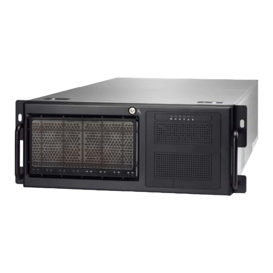
Page 20: About The Product
About the Product The following views show you the product. 1.5.1 System Front View HDD0 HDD1 HDD2 HDD3 HDD4 HDD5 HDD6 HDD7 M1019-FPB Front Panel Control Board (pre-installed) http://www.tyan.com... - Page 21 M1019-FPB Front Panel Control Board Power Button Reset Button NMI Button ID Button LAN2 LED LAN1 LED HDD LED Warning LED Power LED ID Button USB3.0 Port 2 USB3.0 Port 1 http://www.tyan.com...
-
Page 22: System Rear View
PCIE Gen3 x16 Slot (PCIE#7, GPU4) PCIE Gen3 x8 Slot (PCIE#6) PCIE Gen3 x16 Slot (PCIE#5, GPU3) PCIE Gen3 x8 Slot (PCIE#4) PCIE Gen3 x16 Slot (PCIE#3, GPU2) PCIE Gen3 x8 Slot (PCIE#2) PCIE Gen3 x16 Slot (PCIE#1, GPU1) http://www.tyan.com... -
Page 23: Led Definitions
Press ID button when the system is AC (Alternating Current) on, then ID LED will show the system is identified with emitting blue light. Users from remote site could also activate ID LED by input a few commands in IPMI, detailed software support please visit http://www.tyan.com for latest AST2500 user guide. http://www.tyan.com... -
Page 24: Hdd Led
Green 10 Mbps Active Blinking Green Link Green Solid Green 100 Mbps Active Blinking Green Solid Green Link Green Solid Yellow 1000 Mbps Active Blinking Green Solid Yellow Link Yellow Solid Yellow 10 Gbps Active Blinking Yellow Solid Yellow http://www.tyan.com... -
Page 25: System Top View
FAN2 PCIE Gen3 x16 (PCIE#1, GPU1) FAN3 PCIE Gen3 x8 (PCIE#2) FAN4 PCIE Gen3 x16 (PCIE#3, GPU2) FAN5 PCIE Gen3 x8 (PCIE#4) FAN6 PCIE Gen3 x16 (PCIE#5, GPU3) CPU0 PCIE Gen3 x8 (PCIE#6) CPU1 PCIE Gen3 x16 (PCIE#7, GPU4) http://www.tyan.com... - Page 26 NOTE http://www.tyan.com...
-
Page 27: Chapter 2: Setting Up
Caution! To avoid damaging the motherboard and associated components, do not use torque force greater than 7kgf/cm (6.09 lb/in) on each mounting screw for motherboard installation. Do not apply power to the board if it has been damaged. http://www.tyan.com... -
Page 28: Precautions
Working on a system that is connected to a power supply can be extremely dangerous. Follow the guidelines below to avoid damage to FT48B-B7100 or injury to yourself. Ground yourself properly before removing the top cover of the system. -
Page 29: Installing Motherboard Components
2.1.1 Removing the Chassis Cover and Air Ducts Follow these instructions to remove the FT48B-B7100 chassis cover and air ducts. Unscrew the rear cover and then slide the rear top cover off. Press the buttons on the front top cover and slide the cover off. - Page 30 Unscrew to remove the air ducts from the chassis. http://www.tyan.com...
-
Page 31: Opening The Chassis Front Bezel
Follow the following instructions to open the chassis front bezel. Insert the front bezel key (packed in a bag in the accessory box) and rotate the key 90 degrees counterclockwise to unlock the front bezel. Open the front bezel. http://www.tyan.com... -
Page 32: Installing The Cpu And Heatsink
Align and install the processor on the carrier. Locate the CPU socket’s gold arrow. Always start with CPU0 first. Remove the CPU Socket protection cap. Install the carrier assembly on the CPU Socket and make sure the gold arrow is located in the correct direction. http://www.tyan.com... - Page 33 http://www.tyan.com...
- Page 34 (1234). NOTE: When disassembling the heatsink, loosen the screws in reverse order (4321). Repeat the procedures described earlier to install the second processor and heatsink. Place the CPU air duct back and screw it to the chassis. http://www.tyan.com...
-
Page 35: Installing The Expansion Cards
2.1.4 Installing the Expansion Cards FT48B-B7100 has seven expansion slots. Only the PCI-E Gen.3 x16 slots can GPU (Graphic Processing Unit) support cards. Follow these instructions to install the GPU card. Locate the PCI-E Gen.3 x16 slots on the motherboard. Unscrew to take out the dummy brackets. - Page 36 Connect the GPU Power cable. Insert the GPU card into the PCIE Gen. 3 slot and screw the GPU card to the chassis. http://www.tyan.com...
- Page 37 Insert the cable through the air duct opening and place the GPU air duct in place. Screw the GPU air duct to the chassis. http://www.tyan.com...
-
Page 38: Installing The Memory
Align the memory module with the slot. When inserted properly, the memory slot locking levers lock automatically onto the indentations at the ends of the module. Follow the recommended memory population table to install the other memory modules. http://www.tyan.com... - Page 39 http://www.tyan.com...
- Page 40 √ √ √ P0_MCO_DIM_CH_E0 √ √ √ √ √ √ √ P0_MCO_DIM_CH_F0 √ √ √ √ √ √ P1_MCO_DIM_CH_A0 √ √ √ √ √ P1_MCO_DIM_CH_B0 √ √ √ √ P1_MCO_DIM_CH_C0 √ √ √ P1_MCO_DIM_CH_D0 √ √ P1_MCO_DIM_CH_E0 √ P1_MCO_DIM_CH_F0 http://www.tyan.com...
-
Page 41: Installing Hard Drives
2.1.6 Installing Hard Drives The FT48B-B7100 can support up to ten (10) 2.5” HDD/SSD (eight at front, two at rear). Follow these instructions to install a hard drive. Warning!!! Always install the HDD/SSD to the chassis after the chassis is secured on the rack. - Page 42 Place a hard drive into the drive tray. Use four screws to secure the HDD/SSD. Reinsert the HDD tray into the chassis. Press the locking lever to secure the hard drive. Repeat the same procedures to install other HDD trays. http://www.tyan.com...
-
Page 43: Rack Mounting
B: M 6--10 pcs C: M 4-L5--16 pcs 2.2.1 Installing the Server in a Rack Follow these instructions to mount the TYAN FT48B-B7100 into an industry standard 19” rack. NOTE: Before mounting the TYAN FT48B-B7100 in a rack, ensure that all internal components have been installed and that the unit has been fully tested. - Page 44 Installing the Inner Rails to the Unit Screw the mounting ears to the FT48B-B7100 as shown using six M4-L5 screws (C) from the supplied screw kit. Press the latch to draw out the inner rails from each rail assembly. Install the inner sliding rails to each side of the server using five M4-L5 screws (C).
- Page 45 Secure the outer rails to the rack using four M6 (2 front, 2 rear) screws (B) and one nut (A) for each side. Secure the mounting brackets from outside, not inside of the rack. http://www.tyan.com...
- Page 46 Rack Mounting the Server Draw out the middle rail to the latch position. Lift the unit and then insert the inner slide rails into the middle rails. Push the whole system in. http://www.tyan.com...
- Page 47 Secure the mounting ears of the unit to the rack using three M6 screws (B) for each side. Secure the screws on the rear side. http://www.tyan.com...
- Page 48 NOTE http://www.tyan.com...
-
Page 49: Chapter 3: Replacing Pre-Installed Components
S7100 Motherboard, M1019-FPB Front Panel Board, M1244G70-BP6-8 & M7063F86-BP6-2 SATA/SAS HDD Backplane Board, M1081F77-FB-FB48 Board, M7100F48B-PDB Power Distribution Board, PCI-E Riser Card, System Fan and Power Supply Unit etc. 3.0.2 Disassembly Flowchart The following flowchart outlines the disassembly procedures. http://www.tyan.com... -
Page 50: Removing The Cover
Removing the Cover Before replacing any parts you must remove the chassis cover. Follow Section 2.1.1 Removing the Chassis Cover (page 29) to remove the cover of the FT48B-B7100. Replacing the System Fan Follow these instructions to replace the system fan. -
Page 51: Replacing The Fan Board
Replacing the Fan Board Follow these instructions to replace the fan board. Unscrew the fan cage and remove all system fans from the fan cage. Take out the fan cage. Disconnect all cables from the fan board. http://www.tyan.com... - Page 52 Unscrew the fan board to replace a new one. Assemble the fan cage and system fans back into the chassis following the steps described earlier in reverse. http://www.tyan.com...
-
Page 53: Fan Board Features
4-pin Fan Signal Control Header (J7) FAN6 Connector (J6) M1801F77-FB-FT48 Fan Board Form Factor 360mm x 167mm, 4-layer PCB (3) Big 4-pin Power Connector (6) 4-pin Fan Connector Specifications (1) 20-pin Fan Control Header (1) 4-pin Fan Signal Control Header http://www.tyan.com... -
Page 54: Fan Board Led Definition
3.3.2 Fan Board LED Definition FAN Status Green LED Red LED With Fan Speed RPM OK Fan Failed or Without Fan http://www.tyan.com... -
Page 55: Connector Pin Definitions
3.3.3 Connector Pin Definitions J1~J6: 4-pin Fan Connector Definition Definition VDD+12V TACH PW1/PW2/PW3: Big 4-pin Power Connector Definition Definition VDD+12V J8: Fan Control Header Definition Definition TACH1 TACH6 TACH2 TACH3 TACH4 TACH5 PWM2 PWM1 PWM3 http://www.tyan.com... -
Page 56: Replacing The Hdd Backplane Board
Replacing the Fan Board (p. 51) on how to remove the Fan Cage and Fan Board. Disconnect all cables attached to the HDD BP Board. Press the latches to push the HDD module forwards. Unscrew the HDD module’s lower side rails. http://www.tyan.com... - Page 57 Loosen the screws as shown. Unscrew the HDD BP Board for replacement. Prepare a new HDD BP Board and reinstall it into the chassis following the steps in reverse. http://www.tyan.com...
- Page 58 M7063F86-BP6-2 Rear HDD BP Board Disconnect all cables attached to the HDD BP Board. Unscrew the HDD BP Board from the HDD module. Prepare a new HDD BP Board for replacement and reinstall it into the HDD module following the steps in reverse. http://www.tyan.com...
-
Page 59: Hdd Bp Board Features
3.4.1 HDD BP Board Features Front view: Rear view: M1244G70-BP6-8 HDD Backplane Board Form Factor 8-layer PCB (1) 8-pin Power Connector (PW3) (2) Mini-SAS Connector Integrated I/O (8) HDD Connector, 2.5” SAS/SATA 12Gb/s & hot-swap support http://www.tyan.com... - Page 60 Front view: Rear view: M7063F86-BP6-2 HDD Backplane Board Form Factor 8-layer PCB (1) Big 4-pin Power Connector (PW2) (2) 7-pin SATA Connector Integrated I/O (2) HDD Connector, 2.5” SAS/SATA 6Gb/s & hot-swap support http://www.tyan.com...
-
Page 61: Connector Pin Definitions
3.4.2 Connector Pin Definitions M1244G70-BP6-8 HDD Backplane Board PW3: 8-pin Power Connector Definition Definition +12V +12V +12V +12V M7063F86-BP6-2 HDD Backplane Board PW2: Big 4-pin Power Connector Signal Signal P12V_IN VCC5 http://www.tyan.com... -
Page 62: Replacing The Front Panel Board
Replacing the Front Panel Board Follow these instructions to replace the M1019-FPB Front Panel Control Board. Disconnect the power cable and data cable from M1019. Push aside the latch and slide the LED control board unit out of the chassis. http://www.tyan.com... - Page 63 Remove three screws securing the LED control board to the bracket. Lift the LED control board free from the chassis. After replacement, insert the unit into the chassis following the above procedures in reverse. http://www.tyan.com...
-
Page 64: Front Panel Board Features
Power Button Warning LED (red) Reset Button Power LED (green) NMI Button ID Button ID LED (blue) USB3.0 Port 2 LAN2 LED (green) USB3.0 Port 1 LAN1 LED (green) Front Panel Connector (J3) HDD LED (amber) USB3.0 Connector (J34) http://www.tyan.com... -
Page 65: Pin Definitions
P0_RX_N P0_RX_P P1_RX_N P1_RX_P P0_TX_N P0_TX_P P1_TX_N P1_TX_P P0_N P0_P P1_N OC_N P1_P J3: 24-pin Front Panel Header Signal Signal PW_LED+ FP_PWER(3.3V) FP_ID_LED_PWR PW_LED- FP_ID_LED_N HD_LED+ HWM_FAULT_LED- HD_LED- SYS_FAULT_LED- PW_SW# LAN1_ACTLED+ LAN1_ACTLED- RST_SW# FP_ID_LED_BTN_N INTRUDER# FPIO_TEMP_IN LAN2_ACTLED+ NMI_SW# LAN2_ACTLED- http://www.tyan.com... -
Page 66: Replacing The Power Supply
Press and hold the latch to pull the power supply out. After replacing a new power supply, press and hold the latch to push the power supply back into the chassis. http://www.tyan.com... -
Page 67: Replacing The Power Distribution Board
Disconnect the all cables from the power distribution board. Unscrew the power distribution board. Push the power supply cage forwards to take out the power distribution board. Follow the steps described earlier in reverse order to reinstall the power distribution board into the chassis. http://www.tyan.com... -
Page 68: Power Distribution Board Features
Power Distribution Board Features M7100F48B-PDB Power Distribution Board Board Size 82mm x 127.3mm, 6-layer PCB (3) 8-pin power connector (3) 4-pin power connector (2) 20-pin power connector Integrated I/O (1) 24-pin power connector (1) PSMI connector (1) 50-pin golden finger http://www.tyan.com... -
Page 69: Pin Definitions
3.7.2 Pin Definitions J1: PSMI Connector Definition Definition SMBUS_Clock SMBUS_Data SMBUS_Alert PW1/PW4/PW9: 4-pin Power Connector Definition Definition PW6/PW7/PW8: 8-pin Power Connector Definition Definition PW2/PW3: 20-Pin Power Connector Definition Definition http://www.tyan.com... - Page 70 PW5: 24-pin Power Connector Definition Definition 3.3V 3.3V 3.3V PS_ON PW_GD 5VSB 3.3V http://www.tyan.com...
-
Page 71: Replacing The Power Backplane Board
Replacing the Power Backplane Board Follow these instructions to replace the M7063F86-PBP Power Backplane Board. Unscrew the Power BP Board Tray from the chassis. Remove the power distribution board and the bracket beneath. http://www.tyan.com... - Page 72 Unscrew the power backplane board tray. Slide to take out the power backplane board tray. Unscrew to replace with a new power backplane board. Follow the steps described earlier in reverse order to reinstall the power backplane board tray into the chassis. http://www.tyan.com...
-
Page 73: Removing The Motherboard
Make sure you have disconnected all cables and remove all components from the chassis. Unscrew the motherboard. Carefully lift the motherboard from the tray. Prepare a new motherboard and follow the steps described earlier in reverse order to reinstall the motherboard into the chassis. http://www.tyan.com... - Page 74 NOTE http://www.tyan.com...
-
Page 75: Appendix I: How To Recover Uefi Bios For Intel® Xeon® Scalable Processor-Based Platform
UEFI recovery bootloader that would prevent the recovery process itself from working. In no event shall Tyan be liable for direct, indirect, incidental, special or consequential damages arising from the BIOS update or recovery. - Page 76 “Flash update completed. Press any key to reset the system” displayed on screen. Remove the USB disk and reboot. If your system does not have video output or the POST code halts at “FF” on the right-lower portion of the screen, please contact Tyan representatives for RMA service. http://www.tyan.com...
-
Page 77: Appendix Ii: Cable Connection Tables
M7063F86-BP6 Connect to S7100 MB -2 BP Board → SATA cable-1 SATA0 → SATA Cable-2 SATA1 → SGPIO cable SSATA-SGPIO1 4. Fan BP PWR Cable FAN BP to PDB FAN BP Connect to Fan BP PWR → PW1,PW2,PW3 Cable http://www.tyan.com... - Page 78 GPU card-4 Cable-4 8. 2x12P, 2x4P PWR & PSMI Cable PDB Board to S7100 MB PDB Board Connect to S7100 MB 2x12P PWR → PWCN1 Cable 2x4P PWR → PWCN2 Cable-1 2x4P PWR → PWCN3 Cable-2 → PSMI Cable PSMI http://www.tyan.com...
-
Page 79: Appendix Iii: Fan And Temp Sensors
(rpm) Temp Sensor: P1_MOS_Area(RT3) & SYS_AirOutlet(RT2). They detect the system temperature around. NOTE: The system temperature is measured in a scale defined by Intel, not in Fahrenheit or Celsius. http://www.tyan.com... - Page 80 BIOS Temp Sensor Name Explanation: http://www.tyan.com...
- Page 81 The highest temperature of CPU1 DIMM channel D slot P1_MC1_DIM_CH_E The highest temperature of CPU1 DIMM channel E slot P1_MC1_DIM_CH_F The highest temperature of CPU1 DIMM channel F slot PCH_Temp Temperature of PCH SYS_Air_Inlet Temperature of the SYS_Air_Inlet Area http://www.tyan.com...
- Page 82 Fan speed of SYS_FAN5 SYS_FAN6 Fan speed of SYS_FAN6 SYS_FAN7 Fan speed of SYS_FAN7 SYS_FAN8 Fan speed of SYS_FAN8 SYS_FAN9 Fan speed of SYS_FAN9 SYS_FAN10 Fan speed of SYS_FAN10 SYS_FAN11 Fan speed of SYS_FAN11 SYS_FAN12 Fan speed of SYS_FAN12 http://www.tyan.com...
-
Page 83: Appendix Iv: Fru Parts Table
Appendix IV: FRU Parts Table FT48B-B7100 FRU Parts Item Model Number Part Number Picture Description TF-POWER SUPPLY;SBU,1600 FRU-PS-0130 471100000193 W,DELTA,DPS-1600EB B,(S0F),1U MODULE,REV.S0F TF-FAN;12V,PFC1212DE-SP0,4800RPM,120X120 FAN Kit CFAN-0410 541379090002 X38,DELTA, 4-pin HF-HEATSINK;SBU,AL/CU,SOLDERLING+PIPE, Heatsink & 3647-2U-NARROW-PASSIVE HEATSINK, FRU-TH-0220 343T56600001 Cooler 1A0-D042800991, 108.0X78.0X64.0MM, SCREW,FT48B-B7100... - Page 84 NOTE http://www.tyan.com...
-
Page 85: Appendix V: Technical Support
MITAC serves multiple market segments with the industry’s most competitive services to support them. Please feel free to contact us directly for this service at tech-support@tyan.com Help Resources: 1. See the POST codes section of this manual. - Page 86 (RMA) number. The RMA number should be prominently displayed on the outside of the shipping carton and the package should be mailed prepaid. TYAN will pay to have the board shipped back to you. TYAN® FT48B-B7100 Service Engineer’s Manual V1.0a Document No.: D2385-100 http://www.tyan.com...
Need help?
Do you have a question about the FT48B-B7100 and is the answer not in the manual?
Questions and answers