Table of Contents
Advertisement
Quick Links
Advertisement
Table of Contents

Related Manuals for TYAN FT77CB7079


Summary of Contents for TYAN FT77CB7079
- Page 1 FT77CB7079 Service Engineer’s Manual http://www.tyan.com...
- Page 2 http://www.tyan.com...
- Page 3 TYAN products including liability or ® warranties relating to fitness for a particular purpose or merchantability. TYAN retains the right to make changes to produce descriptions and/or specifications at ® any time, without notice. In no event will TYAN...
-
Page 4: Fcc Declaration
There will be danger of explosion if battery is incorrectly replaced. Replace only with the same or equivalent type recommended by manufacturer. Dispose of used battery according to manufacturer instructions and in accordance with your local regulations. http://www.tyan.com... -
Page 5: About This Manual
About this Manual This Manual is intended for experienced users and integrators with hardware knowledge of personal computers. It is aimed to provide you with instructions on installing your TYAN FT77C-B7079. How this guide is organized This guide contains the following parts:... -
Page 6: Safety Information
·When service or repairs have been done, perform routine safety checks to verify that the system is operating correctly. ·Avoid using the system near water, in direct sunlight, or near a heating device. ·Cover the unit when not in use. http://www.tyan.com... -
Page 7: Table Of Contents
Table of Contents Chapter 1: Overview ............... 9 About the TYAN FT77C-B7079 ..........9 Product Models ..............9 Standard Parts List .............. 22 1.4.1 Box Contents ..............22 1.4.2 Accessories ..............22 About the Product ..............23 1.5.1 System Front View ............23 1.5.2... - Page 8 Flash Utility ................ 159 AMIBIOS Post Code (Aptio) ..........160 Appendix I: Fan and Temp Sensors .......... 170 Appendix II: Cable Connection Tables ........175 Appendix III: FRU Parts Table ............ 177 Appendix IV:Glossary ..............179 Appendix V: Technical Support ..........185 http://www.tyan.com...
-
Page 9: Chapter 1: Overview
Chapter 1: Overview About the TYAN FT77C-B7079 ® Congratulations on your purchase of the TYAN FT77C-B7079, a highly optimized rack-mountable 4U barebone system. FT77C-B7079 is designed to ® support dual Intel Xeon E5-2600V3 Series processors and up to 768GB RDIMM/, 1,536GB LRDIMM/ and 3,072GB LRDIMM(3DS* DDR4 Memory), providing a rich feature set and incredible performance. - Page 10 Features TYAN FT77CB7079 (B7079F77CV10HR-2T) Form Factor 4U Rackmount Gross Weight 35 kg System Chassis Model FT77C Dimension (D x W x H) 30.31" x 17.24" x 6.93" (770 x 438 x 176mm) Motherboard S7079GM2NR-2T Buttons (1) RST / (1) ID / (1) PWR w/ LED...
- Page 11 90%, non-condensing at 35° C Humidity RoHS RoHS 6/6 Compliant Barebone (1) FT77C-B7079 Barebone Manual (1) Quick Installation Guide Package Contains Installation CD (1) TYAN installation CD Cable Others (8) GPU power cables TYAN FT77CB7079 (B7079F77CV10HR) System Form Factor 4U Rackmount http://www.tyan.com...
- Page 12 Memory voltage 1.2V (8) PCI-E Gen3 x16 slots / (2) PCI-E Gen3 x8 PCI-E slots(one for mezzanine card) Expansion Slots Pre-install TYAN Riser M2210-L8-1F, PCI-E Gen3 x8 slot (left) Card Port Q'ty (2) GbE ports (1 port shared with IPMI) Controller...
- Page 13 Humidity RoHS RoHS 6/6 Compliant Barebone (1) FT77C-B7079 Barebone Manual (1) Quick Installation Guide Package Contains Installation CD (1) TYAN installation CD Cable Others (8) GPU power cables TYAN FT77CB7079 (B7079F77CV10HR-2T-N) Form Factor 4U Rackmount Gross Weight 35 kg System...
- Page 14 Memory voltage 1.2V (8) PCI-E Gen3 x16 slots / (2) PCI-E Gen3 x8 PCI-E slots(one for mezzanine card) Expansion Slots Pre-install TYAN Riser M2210-L8-1F, PCI-E Gen3 x8 slot (left) Card Port Q'ty (2) 10GbE ports (1 port shared with IPMI) Controller...
- Page 15 (1) FT77C-B7079 w/NV Tesla-aware FW Barebone Barebone Manual (1) Quick Installation Guide Package Contains Installation CD (1) TYAN installation CD (1) CPU air duct / (8) For NV-Tesla GPU card Others brackets Cable Others (8) GPU power cables TYAN FT77CB7079 (B7079F77CV10HR-2T-X)
- Page 16 Memory voltage 1.2V (8) PCI-E Gen3 x16 slots / (2) PCI-E Gen3 x8 PCI-E slots(one for mezzanine card) Expansion Slots Pre-install TYAN Riser M2210-L8-1F, PCI-E Gen3 x8 slot (left) Card Port Q'ty (2) 10GbE ports (1 port shared with IPMI) Controller...
- Page 17 (1) FT77C-B7079 w/Intel Xeon Phi-aware FW Barebone Barebone Manual (1) Quick Installation Guide Package Contains Installation CD (1) TYAN installation CD (1) CPU air duct / (8) For Intel Xeon Phi card Others brackets Cable Others (8) GPU power cables...
- Page 18 Memory voltage 1.2V (8) PCI-E Gen3 x16 slots / (2) PCI-E Gen3 x8 PCI-E slots(one for mezzanine card) Expansion Slots Pre-install TYAN Riser M2210-L8-1F, PCI-E Gen3 x8 slot (left) Card Port Q'ty (2) GbE ports (1 port shared with IPMI) Controller...
- Page 19 (1) FT77C-B7079 w/NV Tesla-aware FW Barebone Barebone Manual (1) Quick Installation Guide Package Contains Installation CD (1) TYAN installation CD (1) CPU air duct / (8) For NV-Tesla GPU card Others brackets Cable Others (8) GPU power cables TYAN FT77CB7079 (B7079F77CV10HR-X)
- Page 20 Memory voltage 1.2V (8) PCI-E Gen3 x16 slots / (2) PCI-E Gen3 x8 PCI-E slots(one for mezzanine card) Expansion Slots Pre-install TYAN Riser M2210-L8-1F, PCI-E Gen3 x8 slot (left) Card Port Q'ty (2) GbE ports (1 port shared with IPMI) Controller...
- Page 21 (1) FT77C-B7079 w/Intel Xeon Phi-aware FW Barebone Barebone Manual (1) Quick Installation Guide Package Contains Installation CD (1) TYAN installation CD (1) CPU air duct / (8) For Intel Xeon Phi card Others brackets Cable Others (8) GPU power cables...
-
Page 22: Standard Parts List
(1) M1262F77C-BP6-10 HDD Backplane (pre-installed) 1.4.2 Accessories If any items are missing or appear damaged, contract your retailer or browse to ® ‟s website for service: http://www.tyan.com. TYAN FT77C-B7079 Accessory Kit (1) Rail kit (2) Rail screw kit (2) CPU heatsink... -
Page 23: About The Product
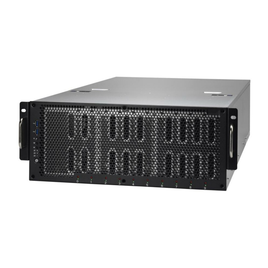
About the Product The following views show you the product. 1.5.1 System Front View http://www.tyan.com... - Page 24 ID LED will show the system is identified with emitting blue light. Users from remote ID(UID) site could also activate ID LED by input a few commands in IPMI, detailed software support please visit http://www.tyan.com latest AST2400 user guide. Press to reset the system. http://www.tyan.com...
-
Page 25: System Rear View
1.5.2 System Rear View Power Supply Cage PCIE x 8 Slot for Mezzanine Card (Optional) ID LED button VGA/USB Port via a dongle cable LAN2 shared with IPMI LAN1 ID LED Expansion Slots http://www.tyan.com... -
Page 26: Led Definitions
Solid Amber Link 1000 Mbps (1Gbps) Blinking Green Solid Amber Active NOTE: 1. When I350-BT2 LAN chip is on, LAN1 and LAN2 can support 10Mbps~1Gbps. 2. When X540-AT2 LAN chip is on, LAN1 and LAN2 can support up to 100Mbps~10Gbps. http://www.tyan.com... - Page 27 (PMBus reading), or hot spot temperature>95deg (PMBus reading), high power, high current, slow fan(<1200rpm). AC present Only 12VSB on(PS off) Blink GREEN or PS in Smart Redundant state Output ON and OK AMBER AC cord unplugged http://www.tyan.com...
-
Page 28: Internal View
1.5.4 Internal View M1713F77C-FPB Front Panel Board Ten 2.5”/3.5” HDD Trays with M1262F77C-BP6-10 Back Plane Board Six system Fans M7059F77-D-PDB Power Distribution Board Power Supply Cage M7059F77-D-PBP Power Backplane Board http://www.tyan.com... -
Page 29: Chapter 2: Setting Up
Caution! To avoid damaging the motherboard and associated components, do not use torque force greater than 7kgf/cm (6.09 lb/in) on each mounting screw for motherboard installation. Do not apply power to the board if it has been damaged. http://www.tyan.com... -
Page 30: Precautions
After replacing optional devices, make sure all screws, springs, or other small parts are in place and are not left loose inside the case. Metallic parts or metal flakes can cause electrical shorts. http://www.tyan.com... -
Page 31: Installing Motherboard Components
Remove two screws on the back side as show in the small diagram. Loosen the two Thumb screws on the back side as show in the small diagram. 2. Push the two buttons in the direction of the arrow, lift the other side top cover http://www.tyan.com... - Page 32 3. Unscrew the top cover and release the latches to remove the top cover from the chassis. 4. Here is the overview after the chassis cover was removed. 5. Unscrew to remove the air duct. http://www.tyan.com...
-
Page 33: Installing The Cpu And Heat Sink
2.1.2 Installing the CPU and Heat sink Follow the steps below on installing CPUs and CPU heat sinks. Locate the CPU socket. Press the lever and unlock the CPU socket. Lift the CPU socket cover up. http://www.tyan.com... - Page 34 Take out the protection cover and place the CPU to the CPU socket; Close the socket cover. Close the socket levers. http://www.tyan.com...
- Page 35 Close the socket levers. http://www.tyan.com...
-
Page 36: Installing The Memory
Align the memory module with the slot. When inserted properly, the memory slot locking levers lock automatically onto the indentations at the ends of the module. NOTE: Before insert the memory, the USB cable3.0 cable should be disconnect first. http://www.tyan.com... -
Page 37: Installing Expansion Cards
2. Insert the GPU card and secure with 1 screw. 3. Insert the card into the slot and secure it with the screws you removed from the bracket. http://www.tyan.com... - Page 38 4. Connect the cables between the expansion card and the power distribution board, the connectors you use should match with the slot you add the card with. 5. Here is the end of the add on card installation. http://www.tyan.com...
-
Page 39: Installing The Mezzanine Card
Follow these instructions to install the Mezzanine Card. Locate the PCI-E Gen3 x8 slot reserved for the Mezzanine card. Push the latches inwards to remove the PCI dummy bracket. 3. Prepare a Mezzanine card (M7059F77-FDR) associated with tray and insert the tray into the slot. http://www.tyan.com... -
Page 40: Installing Hard Drives
The FT77C-B7079 supports 10 2.5” and 3.5‟ Hard Drives. Follow these instructions to install a hard drive. 2.5” Hard Disk Drive Pull the HDD tray out from the chassis. Adjusting the 4 HDD lock to the 2.5” location. Secure the 2 standoff to the 2.5” HDD. http://www.tyan.com... - Page 41 Stuck the HDD Module to the HDD tray. Reinsert the HDD into the HDD tray http://www.tyan.com...
- Page 42 3.5” Hard Disk Drive Adjusting the 4 HDD lock to the 3.5” location. Place the 3.5” HDD into the HDD tray. Reinsert the HDD into the HDD tray http://www.tyan.com...
-
Page 43: Rack Mounting
Maintenance can be performed on the unit while in a rack but it is preferable to install the device in a fully operational condition. Screw Sack Including: A: M5 Washer------ 8pcs B: M5 x 10 ----------8pcs C: M5 x13 -----------2pcs http://www.tyan.com... -
Page 44: Installing The Inner Rails To The Chassis
Screw the mounting ear to each side of FT77 as shown using 3 screws from the supplied screws kit. Push the latch key and draw out the inner rails from sliding rails. Secure inner rails to both sides of the chassis, be sure the five mounting holes are correctly matched. http://www.tyan.com... -
Page 45: Installing The Outer Rails To The Rack
Installing the Outer Rails to the Rack 1. The nut was needed and prepared by the customer. 2. Secure the outer rail to the rack Using the rail and 4 M5 x 10 screws with washer for each side. http://www.tyan.com... -
Page 46: Rack Mounting The Server
1. Draw out the middle rail till the latch position. 2. Lift the chassis and then insert the inner slide rails into the middle rails. 3. Push the chassis in and pull the latch key (A). Then push the whole system into the rack (B). http://www.tyan.com... - Page 47 4. Secure the mounting ears of chassis to the rack with 2 M5 x 13 screws. http://www.tyan.com...
-
Page 48: Chapter 3: Replacing Pre-Installed Components
Motherboard, M1713F77C-FPB Front Panel Board, M1809F77A-FB Board, M2210-L8-1F Riser Card, M7059F77-FDR Mezzanine Card, M1262F77C-BP6-10 HDD Backplane Board, M7059F77-D-PBP Power Backplane Board,M7059F77-D-PDB Power Distribution Board, System Fan and Power Supply etc. Disassembly Flowchart The following flowchart outlines the disassembly procedure. http://www.tyan.com... -
Page 49: Removing The Cover
To replace the power supply follow these instructions. Press the tab as shown in the diagram and pull out the power. Free the power from the power socket. Replace a new single power and reinsert it into the power socket following the above steps in reverse. http://www.tyan.com... -
Page 50: Replacing Hdd Backplane
Replacing HDD backplane Follow these instructions to replace the M1262F77C-BP6-10 HDD Backplane Board. Remove the 4 screws secure the chassis on the left side. Removing the 4 screws on the other side. Disconnect all the HDD backplane cables. http://www.tyan.com... - Page 51 Remove the 13 screws secure the HDD cage. Lift up the HDD cage from the chassis http://www.tyan.com...
-
Page 52: Hdd Back Plane Board Features
SGPIO connector HDD LED connector LEDs 10 HDD active LEDS 10 HDD fault LEDS Board size 377*100MM HDD sequence Port0 Port1 Port2 Port3 Port4 Port5 Port6 Port7 Port8 Port9 Mini SAS0 SATA0 SATA1 Mini SAS1 http://www.tyan.com... - Page 53 3.5.2 Pin Definition J11/J15: SATA Connector Signal Signal GND1 GND3 GND2 SATA0~9: SATA Connector Signal Signal VCC5_PRE VCC5_1 VCC5_2 HDD_PRS_L SAS_LED VCC12_PRE VCC12_1 VCC12_2 SAS_TX+ SAS_TX- SAS_RX- SAS_RX+ SAS_Present_L J13: JTAG Connector Signal Signal JTAG_TCK JTAG_TDO VCC3_3 JTAG_TMS JTAG_TDI http://www.tyan.com...
-
Page 54: Replacing Power Distribution Board
Follow these instructions to replace the M7059F77-D-PDB Power Distribution Board. 1. Unscrew the M7059F77-D-PDB Power Distribution Board. 2. Remove the power distribution board for replacement. 3. Follow the steps described earlier in reverse order to reinstall the power distribution board into the chassis. http://www.tyan.com... - Page 55 3.6.1 Power Distribution Board Features Form Factor W66.93 x L394 (mm), 8-layer PCB Input: (1) 24S+6P Connector Output: Connectors (1) 2x4-pin Power Connector for Fan Board (16) 2x4-pin Power Connector for GPU http://www.tyan.com...
- Page 56 J2: 2×4-Pin ATX Power Connector for FAN Board, the max current is 30A Signal Signal +12V +12V +12V +12V J3 ~ J18: 2×4-Pin ATX Power Connector for GPU, the max current is 20A Signal Signal +12V +12V +12V +12V http://www.tyan.com...
-
Page 57: Replace The Power Backplane Board
Replace the power backplane Board Follow these instructions to replace the M7059F77-D-PBP Power Backplane Board. Make sure to take out three power supply units. Disconnect the PBP Power cable. Remove screw secure the PBP board http://www.tyan.com... - Page 58 Remove the M7059F77-D-PBP bracket. 5. Unscrew the M7059F77-D-PBP from the bracket and replace with a new one. Follow the steps described earlier in reverse order to reinstall the power backplane board. http://www.tyan.com...
- Page 59 3.7.1 Power backplane Features Form Factor W80 x L145 (mm), 8-layer PCB (3) DPS-1200TB B(80-plus Platinum) power connector. (1) FCI 24S+6P,R/A power connector to Connectors S-S7059GM2NR. (1) FCI 24S+6P power connector to M7059F77-D-PDB. (1) ATX 2Px4 power connector http://www.tyan.com...
-
Page 60: Pin Definition
P21~P28 P51~P58 P31~P38 P61~P68 PS1 PWROK +12VRS PS1 PRESENT_N RETRUN_S PS1 SMB_ALERT_N PSON_N 12VSB PS2 PWROK PS0 PWROK PS2 PRESENT_N PRESENT_N PS2 SMB_ALERT_N SMB_ALERT_N SMART_ON Pull up 12VSB J6: EATX Power Connector 4P*2 Signal Signal +12V +12V +12V +12V http://www.tyan.com... - Page 61 J2~J4: EATX Power Connector 4P*2 Signal Signal VCC12 VCC12 VCC12 VCC12 VCC12 VCC12 VCC12 VCC12 VCC12 VCC12 VCC12 VCC12 VCC12 VCC12 VCC12 VCC12 VCC12 VCC12 PSON_N 12VSB SMB_ALERT_N SMART_ON RETRUN_S 12LS +12VRS PRESENT_N PWROK http://www.tyan.com...
-
Page 62: Replacing The Riser Card
Replacing the Riser Card Follow these instructions to replace the M2210-L8-1F Riser Card. 1. Unscrew the power supply cage. 2. Unscrew the riser card bracket from the chassis. 3. Lift out the power supply cage. http://www.tyan.com... - Page 63 4. Unscrew the riser card bracket from the chassis. 4. Take out the riser card bracket. 5. Unscrew to replace with a new riser card. http://www.tyan.com...
-
Page 64: Riser Card Feature
3.8.1 Riser card Feature W31.85 x L94 (mm), 4-layer PCB Form Factor Specification (1) PCI-E Gen3 x8 Slot for non-standard add-on card http://www.tyan.com... -
Page 65: Replacing The System Fan Board
Replacing the System Fan Board 1. Lift the fan which you need to replace up. 2. Remove the 4 screws from the fan cage. http://www.tyan.com... - Page 66 3. Lift the system fan cage from the chassis. 4. Disconnect all the cables from the M1809F77A-FB fan board. 5. Renew the board and tighten the screw place it back to the chassis following the above procedures in reverse. http://www.tyan.com...
-
Page 67: M1801F77-Fan Board Features
3.9.1 M1801F77-Fan Board Features Form Factor W81.4 x L312.28 (mm), 4-layer PCB (4) 1x4P ATX Power Connector for Fan Specifications (6) 2x2-pin Power Connector (1) 2x10-pin System Fan Connector for Motherboard Fan Sequence http://www.tyan.com... -
Page 68: Pin Definition
Tachometer Input7 Tachometer Input3 Tachometer Input8 Tachometer Input4 Tachometer Input9 Tachometer Input5 Tachometer Input10 PWM Output2 PWM Output1 Tachometer Input11 SMB Data Tachometer Input12 SMB Clock 3.3V Standby PWM Output3 J7/J9/J10/J11: 1×4-Pin ATX Power Connector for Fan Definition Definition +12V http://www.tyan.com... -
Page 69: Replacing The Front Panel Board
M1713F77C-FPB Front Panel Board. 1. Unscrew and disconnect both cables from the front panel board. 2. Prepare a new one to replace. Follow the procedure described earlier in reverse order to reinsert the front panel board into the chassis. http://www.tyan.com... -
Page 70: Front Pane Board Features
15*2 Header connect to MB (2) USB3.0 connector LEDs 1 GREEN/BLUE LED for LAN1 and ID 1 GREEN/GREEN LED for LAN2 and HDD 1 GREEN/AMBER LED for LAN3 and BMC 1 power LED Board size 97*45.2MM http://www.tyan.com... -
Page 71: Pin Definition
FP_USB3_RX_P0 FP_USB3_TX_N0 FP_USB3_TX_P0 USB0- USB0+ USB1+ USB1- FP_USB3_TX_P1 FP_USB3_TX_N1 FP_USB3_RX_P1 FP_USB3_RX_N1 VCC_USB J3: 15*2 Header Definition Definition PW_LED+ ID_LED+ PW_LED- ID_LED- HDD_LED+ SYS_FAULT1- HDD_LED- SYS_FAULT2- PWR_SW- LAN1_LED+ LAN1_LED- RESET- ICH_SMBDAT ICH_SMBCLK ID_SW- INTRU# TEMP_SENSOR LAN2_LED+ NMI_SW LAN2_LED- LAN3_LED+ LAN3_LED- http://www.tyan.com... -
Page 72: Replacing The Motherboard
3.11 Replacing the Motherboard After removing all of the aforementioned cables, follow these instructions to remove the motherboard from the chassis. Unscrew the power distribution board bracket. 2. Take out the power distribution board bracket. http://www.tyan.com... - Page 73 3. Disconnect all cables. 4. Unscrew the motherboard to lift it out. http://www.tyan.com...
-
Page 74: Chapter 4: Motherboard Information
Caution! To avoid damaging the motherboard and associated components, do not use torque force greater than 7kgf/cm (6.09 lb/in) on each mounting screw for motherboard installation. Do not apply power to the board if it has been damaged. http://www.tyan.com... -
Page 75: Board Image
Board Image S7079 This picture is representative of the latest board revision available at the time of publishing. The board you receive may not look exactly like the above picture. http://www.tyan.com... -
Page 76: Block Diagram
Block Diagram S7079 Block Diagram http://www.tyan.com... -
Page 77: Mainboard Mechanical Drawing
Mainboard Mechanical Drawing http://www.tyan.com... -
Page 78: Board Parts, Jumpers And Connectors
The board you receive may not look exactly like the above diagram. The DIMM slot numbers shown above can be used as a reference when reviewing the DIMM population guidelines shown later in the manual. For the latest board revision, please visit our web site at http://www.tyan.com. http://www.tyan.com... - Page 79 BIOS Recovery Mode Jumper 3PHD_3 Security Override Mode Jumper Clear BTN1 RTC Reset Button for Clear CMOS PW2/ PW3 SSI 4-pin Power Connector TYAN Module Header Display port SW1/ LED1 D-LED Button/ID LED Power on Button Reset Button Jumper Legend...
- Page 80 SYS_FAN1 SYS_FAN2 COM1 CPU0_FAN SYS_FAN3 0000000000 0000000000 0000000000 COM2 0000000000 0000000000 0000000000 0000000000 0000000000 IPMB J59/J58 0000000000 0000000000 0000000000 0000000000 0000000000 0000000000 0000000000 0000000000 0000000000 0000000000 0000000000 0000000000 0000000000 0000000000 0000000000 0000000000 0000000000 0000000000 0000000000 0000000000 http://www.tyan.com 0000000000 0000000000 0000...
- Page 81 4-pin CPU Fan Connectors Fan PWM Signal +12V Tachometer (Speed) Control J60: Front Panel Connector Signal Signal PWRLED+ FP_PWER(3.3V) IDLED PWRLED- HDDLED+ FAULT_LED-1 HDDLED- FAULT_LED-2 PWR_SW# LAN1_ACTLE+ LAN1_ACTLED- RST_SW# SMBCLK FP_IDLED_BTN_N INTRUSION# FPIO_TEMP_IN LAN2_ACTLED+ NMI_SW# COM1/2: COM Header Signal Signal SOUT http://www.tyan.com...
- Page 82 J81: USB Front Panel Header (blue) Signal Signal USBD- USBD- USBD+ USBD+ J58/J59: Vertical (Type A) USB Connectors Signal DATA2- DATA2+ IPMB1: IPMB Connector Signal Signal BMC_SMB_DATA BMC_SMB_CLK http://www.tyan.com...
- Page 83 3PHD_1 3PHD_4 3PHD_2 3PHD_5 3PHD_3 Caution: The jumpers are only using for engineering debug. We don‟t suggest customers change the jumpers‟ position, which may cause unable to boot device. http://www.tyan.com...
- Page 84 J19: TYAN Module Header Signal Signal P3V3 FRAME_N LAD0 LAD1 PLT_RST_N LAD2 LAD3 CLK_33M DBG_SERIRQ DBG_PRES_N VCC3_AUX TPM_ADDR_MB PCH_TPM_PP_EN J38: Chassis Intrusion Header Signal INTRUSION# Open Open: Use this header to trigger the system chassis intrusion alarm. Short: Use this header to disable the system Short (Default) chassis intrusion alarm.
- Page 85 3PHD_3: Flash Security Override Jumper Signal Signal MFG_MODE_N Pin 1-2 Closed: Normal Mode (Default) Pin 2-3 Closed: Security Override 3PHD_5: ME Recovery Mode Jumper Signal Signal FM_ME_RCVR_N Pin 1-2 Closed: Normal Mode (Default) Pin 2-3 Closed: ME Recovery Mode http://www.tyan.com...
- Page 86 IDLED_BTN PWR_BTN RST_BTN J56/J57 http://www.tyan.com...
- Page 87 P3V3_AUX ID_SW_L State Color Description Blue System identified System not identified NOTE: The ID LED can be activated remotely using IPMI. Please visit the TYAN Web Site at http://www.tyan.com to download the latest IPMI Configuration Guide for more details. http://www.tyan.com...
- Page 88 Some chassis include plastic studs instead of metal. Although the plastic studs are usable, MiTAC recommends using metal studs with screws that will fasten the motherboard more securely in place. Below is a chart detailing what the most common motherboard studs look like and how they should be installed. http://www.tyan.com...
-
Page 89: Installing The Memory
Installing the Memory Before installing memory, ensure that the memory you have is compatible with the motherboard and processor. Check the TYAN Web site at http://www.tyan.com details of the type of memory recommended for your motherboard. ® The Intel... - Page 90 3. Populate the same DIMM type in each channel, specifically - Use the same DIMM size - Use the same # of ranks per DIMM 4. Dual-rank DIMMs are recommended over single-rank DIMMs. http://www.tyan.com...
- Page 91 √ √ √ √ √ √ √ √ √ √ CPU1_DIMM_C0 √ √ √ √ √ √ CPU1_DIMM_C1 √ √ CPU1_DIMM_C2 √ √ √ √ √ √ √ √ √ CPU1_DIMM_D0 √ √ √ √ √ CPU1_DIMM_D1 √ CPU1_DIMM_D2 http://www.tyan.com...
- Page 92 Intel Xeon processor E5-2600v3 product families Support NOTE 1: 1DPC => One dimm per channel NOTE 2: 2DPC => Two dimm per channel Physical Ranks are used to calculate DIMM Capacity. Supported DRAM Densities are 4Gb, 8Gb. http://www.tyan.com...
-
Page 93: Installing Add-In Cards
Doing so allows air to circulate within the chassis more easily, thus improving cooling for all installed devices. NOTE: You must always unplug the power connector from the motherboard before performing system hardware changes to avoid damaging the board or expansion device. http://www.tyan.com... -
Page 94: Installing The Power Supply
S7079 motherboard. The S7079 supports EPS 12V power supply. PWR1: 4-Pin Power Connector Signal Signal +12V PWR2: 4-Pin Power Connector Signal Signal +12V NOTE: You must unplug the power supply before plugging the power cables to motherboard connectors. http://www.tyan.com... -
Page 95: Chapter 5: Bios Setup
Select the previous value/setting of the field <+> Select the next value/setting of the field <F8> Load Fail Safe default configuration values of the menu <F3> Load the Optimal default configuration values of the menu <F4> Save and exit <Enter> Execute command or select submenu http://www.tyan.com... - Page 96 BIOS menus are continually changing due to continual BIOS updates over the product lifespan of the motherboard. The BIOS menus provided are current as of the date when this manual was written. Please visit TYAN‟s website at http://www.tyan.com for information on BIOS updates available for this specific motherboard.
-
Page 97: Main Menu
It displays BIOS related information. Memory Information This displays the total memory size. System Date Adjust the system date. MM (Months): DD (Days): YYYY (Years) System Time Adjust the system clock. HH (24 hours format): MM (Minutes): SS (Seconds) Access Level Read only. http://www.tyan.com... -
Page 98: Advanced Menu
ACPI Settings System ACPI Parameters. Hardware Health Configuration Hardware health Configuration Parameters. Onboard Device Configuration Onboard Device Configuration. PCIe Slot Configuration Onboard PCIe Slot Configuration WatchDog Timer Configuration WatchDog Configuration ASPEED Super IO Configuration System Super IO Chip parameters http://www.tyan.com... - Page 99 Network stack Settings CSM Configuration CSM Configuration, Enable/Disable Option ROM execution setting,etc Trusted Computing (optional function) Trusted Computing (TPM) settings. NOTE: If no TPM chipset is on, the Trusted Computing submenu will not appear. USB Configuration USB Configuration Parameters. http://www.tyan.com...
- Page 100 ACPI Settings Enable ACPI Auto Configuration Enable or disable BIOS ACPI Auto Configuration. Disabled / Enabled Enable Hibernation Enables or disables System ability to Hibernate (OS/S4 Sleep State). This option may not be effective with some OS. Disabled / Enabled http://www.tyan.com...
- Page 101 PWM Minimal Duty Cycle Duty Cycle control range 30% Duty Cycle / 45% Duty Cycle / 60% Duty Cycle BMC Alert Beep BMC Alert Beep On/Off. On / Off PMBus Support Disabled / Enabled Number of PSU 1 / 1+1 / 2+1 http://www.tyan.com...
- Page 102 5.3.2.1 Sensor Data Register Monitoring When you enter the Sensor Data Register Monitoring submenu, you will see the following dialog window pop out. Please wait 8~10 seconds. NOTE 1: SDR can not be modified. Read only. http://www.tyan.com...
- Page 103 http://www.tyan.com...
- Page 104 Enabled with iSCSI / Enabled with PXE / Disabled Chassis Intrusion detect Enabled: When a chassis open event is detected ,the BIOS will record the event. Disabled / PXE NMI Button Enable or disable NMI button. Enabled / Disabled http://www.tyan.com...
- Page 105 Wait for “F1” if error Wait for F1 stop when BIOS has error appeared. Enabled / Disabled http://www.tyan.com...
- Page 106 Enabled/Disabled PCIe Slot OPTROM Configuration. Enabled / Disabled PCIe Slot4 OPROM Enabled/Disabled PCIe Slot OPTROM Configuration. Enabled / Disabled PCIe Slot5&6 OPROM Enabled/Disabled PCIe Slot OPTROM Configuration. Enabled / Disabled PCIe Slot7&8 OPROM Enabled/Disabled PCIe Slot OPTROM Configuration. Enabled / Disabled http://www.tyan.com...
- Page 107 PCIe Slot9 Link Speed Enabled/Disabled PCIe Slot OPTROM Configuration. Auto / Gen 1 (2.5GT/s) / Gen 2 (5GT/s) / Gen 3 (8GT/s) PCIe Slot10/11/12 Link Speed Enabled/Disabled PCIe Slot OPTROM Configuration. Auto / Gen 1 (2.5GT/s) / Gen 2 (5GT/s) http://www.tyan.com...
- Page 108 Watchdog Timer Configuration Watch Dog Mode Watch Dog Mode Help. Disabled / POST / OS / PowerON NOTE: Watch Dog Timer will appear when Watch Dog Mode is not set to [Disabled]. Watch Dog Timer Watch Dog Timer Help. http://www.tyan.com...
- Page 109 5.3.6 ASPEED Super IO Configuration Super IO Chip Read only. http://www.tyan.com...
- Page 110 / IO=3F8h, IRQ=3, 4, 5, 6, 7, 9, 10, 11, 12; / IO=2F8h; IRQ=3, 4, 5, 6, 7, 9, 10, 11, 12; / IO=3E8h, IRQ=3, 4, 5, 6, 7, 9, 10, 11, 12; / IO=2E8h, IRQ=3, 4, 5, 6, 7, 9, 10, 11, 12; http://www.tyan.com...
- Page 111 Enable or disable System wake on alarm event. Select Fixed time, system will wake on the hr ::min ::sec specified. Select Dynamic Time, System will wake on the current time+ increase minute(s) Disabled / Fixed Time / Dynamic Time http://www.tyan.com...
- Page 112 The settings specify how the host computer (which the user is using) will exchange data. Both computers should have the same or compatible settings. NOTE: Console Redirection Settings menu only appear when Console Redirection was set to [Enabled]. Legacy Console Redirection Setting Legacy Console Redirection Setting http://www.tyan.com...
- Page 113 0 if the num of 1‟s in the data bits is even. Odd: parity bit is 0 if the num of 1‟s in the data bits is odd. Mark: parity bit is always 1. Space: parity bit is always 0. Mark and Space parity do not allow for error detection. None / Even / Odd / Mark / Space http://www.tyan.com...
- Page 114 VT100 / LINUX / XTERMR6 / SCO / ESCN / VT400 Redirection After BIOS POST The settings specify if bootloader is selected than Legacy console redirection is disabled before booting to Legacy OS. Default value is always enable means Legacy. Always Enabled / Bootloader http://www.tyan.com...
- Page 115 5.3.8.2 Legacy OS Redirection Settings Legacy OS Redirection Resolution Select a COM port to display redirection of Legacy OS and Legacy OPROM Messages. COM1 / COM2 http://www.tyan.com...
- Page 116 115200 / 9600 / 19200 / 38400 / 57600 Flow Control Flow Control can prevent data loss from buffer overflow. When sending data, if the receiving buffers are full, a „stop‟ signal can be sent to stop the data flow. Once the http://www.tyan.com...
- Page 117 „start‟ signal can be sent to restart the flow. Hardware flow control uses two wires to send start/stop signal. None / Hardware RTS/CTS Data Bits / Parity / Stop Bits Read only. http://www.tyan.com...
- Page 118 Enables or Disables 64bit capable Devices to be decoded in Above 4G Address Space(Only if System supports 64 bit PCI decoding). Enable / Disabled SR-IOV Support If system has SR-IOV capable PCIe Devices, this option Enables or Disables Single Root IO Virtualization Support. Enable / Disabled http://www.tyan.com...
- Page 119 5.3.9.1 PCI Express settings Maximum Payload Set maximum payload of PCI express device or allow system BIOS to select the value. Auto / 128 Bytes / 256 Bytes / 512 Bytes / 1024 Bytes /2048 Bytes / 4096 Bytes http://www.tyan.com...
- Page 120 If supported by hardware and set to „enabled‟, the Downstream Port disables its traditional Devices number field being 0 enforcement when turning a Type1 Configuration request into a Type0 configuration request, permitting access to Extended Function in an ARI Device immediately below the Port. Enable / Disabled http://www.tyan.com...
- Page 121 Controls the execution of UEFI and legacy PXE OpROM Do not launch / UEFI only / legacy / legacy first / UEFI first Other PCI devices Determines OpRom execution policy for devices other than network, storage, or video legacy / UEFI first http://www.tyan.com...
- Page 122 If no TPM chipset is on, the Trusted Computing submenu will not appear. Security Device Support Enable or disable BIOS support for security device. O.S. will not show Security device. O.S. will not show Security Device. TCG EFI protocol and INT1A interface will not be available. Enabled / Disable http://www.tyan.com...
- Page 123 EHCI Hand-off This is a workaround for OSes without EHCI hand-off support. The EHCI ownership change should be claimed by EHCI driver. Enabled / Disabled USB Mass Storage Driver Support Enable/Disable USB Mass Storage Driver Support Enabled / Disabled http://www.tyan.com...
- Page 124 Maximum time the device will take before it properly reports itself to the Host Controller. AUTO uses default value: for a Root port it is 100 ms, for a Hub port the delay is taken from Hub descriptor. Auto / Manual http://www.tyan.com...
-
Page 125: Intel Rcsetup Menu
Intel RCSetup Menu Processor Configuration Processor Parameters. Advanced Power Management Configuration Advanced power management Parameters. Common RefCode Configuration Common RefCode Configuration. QPI Configuration QPI Configuration Memory Configuration Memory Configuration I/O Configuration I/O Configuration PCH Configuration PCH Configuration Miscellaneous Configuration Miscellaneous Configuration http://www.tyan.com... - Page 126 OS (Windows Server 2003 SP1, Windows XP SP2, SuSE Linux 9.2, RedHat Enterprise 3 Update 3). Enabled / Disabled Enables the Vanderpool Technology, takes effect after reboot Enable / Disable Enable SMX Enables Safer Mode Extensions. Enable / Disable http://www.tyan.com...
- Page 127 5.4.1.1 CPU Socket0/1 Configuration http://www.tyan.com...
- Page 128 5.4.2 Advanced Power Management Configuration Power Technology Enable the power management features. Custom / Disabled / Energy Efficient http://www.tyan.com...
- Page 129 5.4.2.1 CPU P State Control EIST (P-States) When enabled, OS sets CPU frequency according load, when disabled, CPU frequency is set at max non-turbo. Enabled / Disable Turbo Mode Enable/Disable Turbo Mode. Enabled / Disable http://www.tyan.com...
- Page 130 C0/C1 state / C2 state / C6 (non Retention) state / C6 (Retention State) CPU C3 Report Enable/Disable CPU C3 (ACPI C2) report to OS. Enable / Disable CPU C6 Report Enable/Disable CPU C6 (ACPI C3) report to OS. Enable / Disable http://www.tyan.com...
- Page 131 Common RefCode Configuraion MMIOH Base Select MMIOH Base 56T / 48T / 24T MMIO High Size Select MMIO High Size 256G / 128G / 512G / 1024G NUMA Enable or Disable Non uniform Memory Access (NUMA). Enabled / Disabled http://www.tyan.com...
- Page 132 Select the QPI Link Frequency. Auto / 6.4GT/s / 9.6GT/s / 8.0GT/s / Auto Limited Link L0p Enable Link L0p Enable: Disable, Enable, Auto (default) Enabled / Disabled Link L1 Enable Link L1 Enable: Disable, Enable, Auto (default) Enabled / Disabled http://www.tyan.com...
- Page 133 5.4.4.1 QPI Status Submenu Read only http://www.tyan.com...
- Page 134 /2667 / Reserved / Reserved / Reserved / Reserved ECC Support Select the memory type supported by this platform. Auto / Disabled / Enabled Memory Type RDIMMs only / UDIMMs only / UDIMMs and RDIMMs Data Scrambling Enabled / Disabled / Auto http://www.tyan.com...
- Page 135 5.4.5.1 Memory Topology Configuration Read only http://www.tyan.com...
- Page 136 5.4.5.2 Memory Thermal Configuration Set Throttling Mode Configure Thermal throttling mode. Select OLTT or CLTT mode. Disabled / OLTT / CLTT http://www.tyan.com...
- Page 137 Memory Map Configuration Channel Interleaving Select Channel Interleaving setting Auto / 1-way Interleave / 2-way Interleave / 3-way Interleave / 4-way Interleave Rank Interleaving Select rank Interleaving setting Auto / 1-way Interleave / 2-way Interleave / 4-way Interleave / 8-way Interleave http://www.tyan.com...
- Page 138 Disabled / Mirror / Lockstep Mode Lockstep x4 DIMMs Enable / Disable Lockstep for x4 DIMMs Auto / Disabled / Enabled Memory Rank Sparing Enable / Disable Memory Rank Sparing Disabled / Enabled Device Tagging Enable / Disable Device Tagging Disable / Enable http://www.tyan.com...
- Page 139 5.4.6 I/O Configuration Submenu Read only http://www.tyan.com...
- Page 140 5.4.6.1 IOAT Configuration Submenu Enable IOAT Control to enable / disable IOAT devices Disable / Enabled http://www.tyan.com...
- Page 141 Intel® VT for Directed I/O Configuration Submenu ® Intel VT for directed I/O (VT-d) ® Enable/Disable Intel I/O Virtualization Technology for directed I/O (VT/d) by reporting the I/O device assignment to VMM through DMAR ACPI Tables Disable / Enabled http://www.tyan.com...
- Page 142 5.4.7 PCH Configuration Read Only http://www.tyan.com...
- Page 143 5.4.7.1 PCH Device Configuration PCH state after G3 Select S0/S5 for ACPI state after a G3 S0 / S5 / Last State http://www.tyan.com...
- Page 144 5.4.7.2 PCH sSATA Configuration http://www.tyan.com...
- Page 145 Enable/Disable SATA Ports Hot Plug Support. Disabled / Enabled Spin Up Device AHCI Supports Staggered Spin-up Disabled / Enabled sSATA Device Type Indentify the SATA port is connected to Solid State Drive or Hard Disk Drive Hard Disk Drive / Solid State Drive http://www.tyan.com...
- Page 146 5.4.7.3 PCH SATA Configuration http://www.tyan.com...
- Page 147 Support Aggressive Li Enable or Disable Aggressive Li Disabled / Enabled SATA Port 0/1/2/3/4/5 Port 0/1/2/3/4/5 Disabled / Enabled Hot Plug Enable/Disable SATA Ports Hot Plug Support. Disabled / Enabled Spin Up Device AHCI Supports Staggered Spin-up Disabled / Enabled http://www.tyan.com...
- Page 148 Indentify the SATA port is connected to Solid State Drive or Hard Disk Drive Hard Disk Drive / Solid State Drive 5.4.7.4 USB Configuration xHCI Mode Mode of operation of xHCI controller. Auto / Smart Auto / Enabled / Disabled / Manual http://www.tyan.com...
- Page 149 5.4.8 Miscellaneous Configuration Active Video Select active video type Onboard Device / Offboard Device http://www.tyan.com...
-
Page 150: Server Management
Server Management http://www.tyan.com... - Page 151 Choose options for reactions to a full SEL. Do Nothing / Erase Immediately Log EFI Status Codes Disable the logging of EFI Status Codes or log only error code or only progress code or both. Both / Disabled / Error Code / Progress Code http://www.tyan.com...
- Page 152 BMC Network Configuration Configuration Address Source Select the configure LAN channel parameters statically or dynamically (by BIOS or BMC). Unspecified option will not modify any BMC network parameters during BIOS phase. Current Setting / Static / Dynamic-Obtained by BMC http://www.tyan.com...
-
Page 153: Security
Security Password Description Read only. Administrator Password Install or change the password. User Password Install or change the password. http://www.tyan.com... - Page 154 5.6.1 Security Flash Update Read Only http://www.tyan.com...
-
Page 155: Boot
Select the keyboard NumLock state. Off / On Quiet Boot Enable or disable Quiet Boot option. Disabled / Enabled Endless Boot Enable or disable Endless Boot. Disabled / Enabled Boot Option #1/Boot Option #2 Select the first boot device. Device Name / Disabled http://www.tyan.com... - Page 156 5.7.1 Delete Boot Option Configuration Delete Boot Option #1 Sets the system boot order. Device Name / Select one to Delete http://www.tyan.com...
-
Page 157: Save & Exit
Discard Changes and Reset Reset system setup without saving any changes. Save Options Read only. Save Changes Save changes done so far to any of the setup options. Discard Changes Discard changes done so far to any of the setup options. http://www.tyan.com... - Page 158 Restore Defaults Restore/Load Default values for all the setup options. Save as User Defaults Save the changes done so far as User Defaults. Restore User Defaults Restore the User Defaults to all the setup options. http://www.tyan.com...
-
Page 159: Chapter 6: Diagnostics
BIOS flash failure, you must contact your dealer for a replacement BIOS. There are no exceptions. TYAN does not have a policy for replacing BIOS chips directly with end users. In no event will TYAN be held responsible for damages done by the end user. -
Page 160: Amibios Post Code (Aptio)
Description 0x00 Note used Progress Codes 0x01 Power on. Reset type detection (soft/hard). 0x02 AP initialization before microcode loading 0x03 North Bridge initialization before microcode loading 0x04 South Bridge initialization before microcode loading 0x05 OEM initialization before microcode loading http://www.tyan.com... - Page 161 Status Code Description 0x06 Microcode loading 0x07 AP initialization after microcode loading 0x08 North Bridge initialization after microcode loading 0x09 South Bridge initialization after microcode loading 0x0A OEM initialization after microcode loading 0x0B Cache initialization http://www.tyan.com...
- Page 162 Pre-Memory South Bridge initialization (South Bridge module 0x1A specific) Pre-memory South Bridge initialization (South Bridge module 0x1B specific) Pre-Memory South Bridge initialization (South Bridge module 0x1C specific) 0x1D – 0x2A OEM pre-memory initialization codes Memory initialization. Serial Presence Detect (SPD) data 0x2B reading http://www.tyan.com...
- Page 163 Post-Memory South Bridge initialization (South Bridge 0x3C module specific) Post-Memory South Bridge initialization (South Bridge 0x3D module specific) Post-Memory South Bridge initialization (South Bridge 0x3E module specific) 0x3F – 0x4E OEM post memory initialization codes 0x4F DXE PIL is started http://www.tyan.com...
- Page 164 Reserved for future AMI progress codes S3 Resume Error Codes 0xE8 S3 Resume failed 0xE9 S3 Resume PPI not found 0xEA S3 Resume Boot Script error 0xEB S3 OS wake error 0xEC – 0xEF Reserved for future AMI error codes http://www.tyan.com...
- Page 165 Memory was installed twice (installPEIMemory routine in PEI Core called twice). Recovery started DXEIPL was not found. DXE Core Firmware Volume was not found. Recovery failed S3 Resume failed Reset PPI is not available. DXE Phase Status Code Description 0x60 DXE Core is started. http://www.tyan.com...
- Page 166 South Bridge DXE initialization (South Bridge module 0x74 specific) South Bridge DXE initialization (South Bridge module 0x75 specific) South Bridge DXE initialization (South Bridge module 0x76 specific) South Bridge DXE initialization (South Bridge module 0x77 specific) 0x78 ACPI module initialization http://www.tyan.com...
- Page 167 Reserved for future AMI codes 0xA0 IDE initialization is started 0xA1 IDE Reset 0xA2 IDE Detect 0xA3 IDE Enable 0xA4 SCSI initialization is started. 0xA5 SCSI Reset 0xA6 SCSI Detect 0xA7 SCSI Enable 0xA8 Setup Verifying Password 0xA9 Start of Setup http://www.tyan.com...
- Page 168 No Space for Legacy Option ROM 0xD6 No Console Output Devices are found. 0xD7 No Console Input Devices are found. 0xD8 Invalid password 0xD9 Error loading Boot Option (LoadImage returned error) 0xDA Boot Option is failed (StartImage returned error). http://www.tyan.com...
- Page 169 System is waking up from the S3 sleep state. 0x40 System is waking up from the S4 sleep state. System has transitioned into ACPI mode. Interrupt controller 0xAC is in APIC mode. System has transitioned into ACPI mode. Interrupt controller 0xAA is in APIC mode. http://www.tyan.com...
-
Page 170: Appendix I: Fan And Temp Sensors
(rpm) Temp Sensor: LAN_Area_Temp(RT11), SYS_Air_Inlet(U14). They detect the system temperature around. NOTE: The system temperature is measured in a scale defined by Intel, not in Fahrenheit or Celsius. http://www.tyan.com... - Page 171 BIOS Temp Sensor Name Explanation: http://www.tyan.com...
- Page 172 http://www.tyan.com...
- Page 173 Temperature of CPU1 DIMM C1 Slot CPU1_DIMM_C2 Temperature of CPU1 DIMM C2 Slot CPU1_DIMM_D0 Temperature of CPU1 DIMM D0 Slot CPU1_DIMM_D1 Temperature of CPU1 DIMM D1 Slot CPU1_DIMM_D2 Temperature of CPU1 DIMM D2 Slot BIOS FAN Sensor Name Explanation SYS_FAN_1 Fan speed of SYS_FAN_1 http://www.tyan.com...
- Page 174 SYS_FAN_2 Fan speed of SYS_FAN_2 SYS_FAN_3 Fan speed of SYS_FAN_3 SYS_FAN_4 Fan speed of SYS_FAN_4 SYS_FAN_5 Fan speed of SYS_FAN_5 SYS_FAN_6 Fan speed of SYS_FAN_6 http://www.tyan.com...
-
Page 175: Appendix Ii: Cable Connection Tables
4. SATA PWR & Mini-SAS & SATA Cable S7079 M/B to HDD BP S7079 Connect to HDD BP → J42 (Mini-SAS cable-1) Mini-SAS 0 → J32 (Mini-SAS cable-2) Mini-SAS 1 → J11 (SATA Cable-1) SATA 4 → J15 (SATA Cable-2) SATA 5 → → http://www.tyan.com... - Page 176 J17 or J18 GPU1 → J15 or J16 GPU2 → J13 or J14 GPU3 → J11 or J12 GPU4 → J9 or J10 GPU5 → J7 or J8 GPU6 → J5 or J6 GPU7 → J3 or J4 GPU8 http://www.tyan.com...
-
Page 177: Appendix Iii: Fru Parts Table
CCBL-146H 422786600003 FRU-CS-0220 422T42300011 MINI-SAS CABLE, 1000mm CCBL-0688 422797000003 MINI-SAS CABLE, 800mm FRU-CS-0250 422T47600011 Display External Port Delta, DPS-1600CB A,(00F), 1600W Power Supply FRU-PS-0020 471100000246 120*120*38MM w/ holding bracket FRU-TS-0040 5412T4760009 Rack CRAL-0150 340783300039 Slide Rail Kit Mounting Kit http://www.tyan.com... - Page 178 PCBA w/ associate tray FRU-RC-0010 Mezz card M7059F77A-X540 5411T4760022 PCBA w/ associate tray FRU-RC-0030 M7059F77A-I350 5411T4760023 PCBA w/ associate tray FRU-RC-0040 For passively-cooled GPU cards w/ Airduct FRU-TA-0010 343T47600001 depth within 10.5” For Intel Xeon Phi GPU bracket FRU-SO-0050 5412T5060005 brackets(w/screws) http://www.tyan.com...
-
Page 179: Appendix Iv:glossary
CPU can manipulate data in a buffer before copying it to a disk drive. While this improves system performance (reading to or writing from a disk drive a single time is much faster than doing so repeatedly) there is the possibility of losing your data http://www.tyan.com... - Page 180 (like soundcards or keyboards) to access the main memory without involving the CPU. This frees up CPU resources for other tasks. As with IRQs, it is vital that you do not double up devices on a single line. Plug-n-Play devices will take care of this for you. http://www.tyan.com...
- Page 181 ROM chip which can, unlike normal ROM, be updated. This allows you to keep ® ‟s up with changes in the BIOS programs without having to buy a new chip. TYAN BIOS updates can be found at http://www.tyan.com ESCD (Extended System Configuration Data): a format for storing information about Plug-n-Play devices in the system BIOS.
- Page 182 Plug-n-Play require you to reconfigure your system each time you add or change any part of your hardware. PXE (Preboot Execution Environment): one of four components that together make up the Wired for Management 2.0 baseline specification. PXE was http://www.tyan.com...
- Page 183 Sleep/Suspend mode: in this mode, all devices except the CPU shut down. SDRAM (Static RAM): unlike DRAM, this type of RAM does not need to be refreshed in order to prevent data loss. Thus, it is faster and more expensive. http://www.tyan.com...
- Page 184 CPUs without damaging the sensitive CPU pins. The CPU is lightly placed in an open ZIF socket, and a lever is pulled down. This shifts the processor over and down, guiding it into the board and locking it into place. http://www.tyan.com...
-
Page 185: Appendix V: Technical Support
TYAN serves multiple market segments with the industry's most competitive services to support them. "TYAN's tech support is some of the most impressive we've seen, with great response time and exceptional organization in general" - Anandtech.com ® You can contact TYAN Technical Support by using our Online Support System: http://12.230.196.231/helpstar/hsPages/login.aspx?ReturnUrl=%2fhelpstar%2fhsP... - Page 186 Return Merchandise Authorization (RMA) number. The RMA number should be prominently displayed on the outside of the shipping ® carton and the package should be mailed prepaid. TYAN will pay to have the board shipped back to you ®...
Need help?
Do you have a question about the FT77CB7079 and is the answer not in the manual?
Questions and answers