Table of Contents
Advertisement
Quick Links
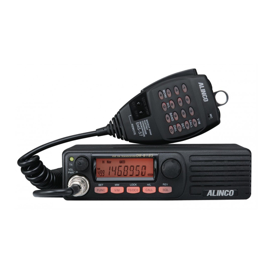
VHF FM Mobile Transceiver
DR-B185HT
DR-B185HE
Instruction Manual
Thank you for purchasing your new Alinco transceiver.
Please read this manual carefully before using the
product to ensure full performance, and keep this
manual for future reference as it contains information
on after-sales services. In case addendum or errata
sheets are included with this product, please read
those materials and keep them together with this
instruction manual for future reference.
Advertisement
Table of Contents

Subscribe to Our Youtube Channel
Related Manuals for Alinco DR-B185HT


Summary of Contents for Alinco DR-B185HT
-
Page 1: Instruction Manual
VHF FM Mobile Transceiver DR-B185HT DR-B185HE Instruction Manual Thank you for purchasing your new Alinco transceiver. Please read this manual carefully before using the product to ensure full performance, and keep this manual for future reference as it contains information on after-sales services. -
Page 2: Before Transmitting
Features Introduction ■ Output power selectable (Hi/Lo) Thank you very much for purchasing this excellent Alinco transceiver. Our products are ranked among the finest in the world. This radio has ■ PC-programmable been manufactured with state of the art technology and it has been tested ■... - Page 3 Conformity Information This equipment generates, uses, and can radiate radio frequency energy Alinco, Inc. Electronics Division hereby declare on our sole responsibility that and, if not installed and used in accordance with the instruction manual, the product(s) listed below comply the essential requirements of the Directive may cause harmful interference to radio communications.
- Page 4 WARNING To prevent any hazard during operation of Alinco’s radio product, in this ALART manual and on the product you may find symbols shown below. Please read and understand the meanings of these symbols before starting to „ Environment and condition of use: use the product.
- Page 5 WARNING „ About power-supply: Do not use multiple radios in very close proximity. It may cause interference and/or damage to the product(s). Use only appropriate, reliable and certified power supply of correct voltage and capacity. The manufacturer declines any responsibilities against loss of life and property due to a failure of this product when used with or as a Do not connect cables in reverse polarity.
- Page 6 WARNING „ In case of emergency: CAUTION In case of the following situation(s), please turn off the product, switch „ Environment and condition of use: off the source of power, then remove or unplug the power-cord. Please contact your local dealer of this product for service and assistance. Do not use the product until the trouble is resolved.
- Page 7 WARNING „ About transceiver Do not connect devices other than specified ones to the jacks and ports on the product. It may result in damage to the devices. Turn off and remove the power-source (AC cable, DC cable, battery, cigar-cable, charger adapter etc) from the product when the product is not in use for extended period of time or in case of maintenance.
-
Page 8: Table Of Contents
CONTENTS Supplied Accessories ............1 Basic Operations ..............15 SWITCHING THE POWER ON/OFF ..........15 SUPPLIED ACCESSORIES ............1 MOBILE INSTALLATION ..............2 ADJUSTING THE VOLUME ............15 Initial Installation ..............2 ADJUSTING FREQUENCY/CHANNEL THROUGH THE DIAL ..15 SQUELCH LEVEL SETTING ............15 DC POWER CABLE CONNECTION .......... - Page 9 CONTENTS Cable Clone ................37 SETTING THE MESSAGE DISPLAYED WHEN TRUNING ON THE POWER ................... 26 Maintenance ................38 BCLO SETTING ................26 DEFAULT SETTING AFTER RESETTING DR-B185....... 38 OFFSET FREQUENCY ..............27 TO RESET ..................38 VFO UPPER LIMIT ................27 TROUBLE SHOOTING ..............
-
Page 10: Supplied Accessories
•DR-B185HE : EMS-53 Plain The standard accessories may vary slightly depending on the version you have purchased. Please contact your local authorized Alinco dealer should you have any questions. Alinco and authorized dealers are not responsible for any typographical errors there may be in this manual. Standard accessories may change without notice. -
Page 11: Mobile Installation
Initial Installation „ „ Mobile installation Determine the appropriate angle of the transceiver, using the 3 screw ▼ hole positions on the side of the mounting bracket. The transceiver may be installed in any position in your car, where the controls and microphone are easily accessible and it does not interfere with the safe operation of the vehicle. -
Page 12: Dc Power Cable Connection
Initial Installation „ „ DC Power Cable Connection Reconnect any wiring removed from the negative terminal. Mobile Operation The vehicle battery must have a nominal rating of 12V. Never connect the transceiver to a 24V battery. Be sure to use a 12V vehicle battery that has sufficient current capacity. - Page 13 Initial Installation Fixed Station Operation Connect the transceiver’s DC power connector to the connector on the DC power cable. In order to use this transceiver for fixed station operation, you will need Press the connectors firmly together until the locking tab clicks. ▼...
-
Page 14: Power Supply Voltage Display
Initial Installation „ „ „ „ Accessories Connections Power supply voltage Display After connecting the transceiver to the power supply, the supply voltage External Speaker can be displayed on LCD by pressing the key together with the If you plan to use an external speaker, choose a speaker with an key. - Page 15 Initial Installation Microphone For voice communications, connect a provided microphone into the socket on the front of the main unit. Turn the ring firmly on the plug until it locks. Attach the supplied microphone hanger in an appropriate location using the screws included in the screw set. Microphone Antenna Microphone (EMS-53)
-
Page 16: Front Panel
Getting Acquainted „ „ Front panel NO. KEY FUNCTION • In VFO mode Switches the CALL channel/VFO mode (for the frequency being edited). • In memory mode CALL Switches the CALL channel/memory mode. • In channel display mode LOCK S w i t c h e s t h e C A L L c h a n n e l / c u r r e n t l y TS/DCS CALL FUNC... -
Page 17: Press
Getting Acquainted NO. KEY FUNCTION NO. KEY FUNCTION • In VFO mode/memory mode Sets the reverse function. Press and hold for 2 seconds to enter • In VFO mode/memory mode parameter setting mode. FUNC Rotate to select a channel. • In channel display mode Press to set the shift function. -
Page 18: Operations When Turning On The Power While Pressing The Following Respective Keys
E x t . S p e a k e r optional external speaker. Terminal About PC programming PC programming utility software is downloadable from www. alinco.com site. An optional ERW-7 PC cable is required. DATA terminal is the port for PC cable connection also. -
Page 19: Display
Getting Acquainted „ „ DISPLAY NO. KEY FUNCTION Lights up when Narrow Band is set. Turns off when 5 6 7 10 11 12 Wide Band is set. Lights up when the shift direction is positive. Lights up when the shift direction is negative. Lights up when the 2-tone is set. -
Page 20: Microphone
Getting Acquainted „ „ microphone MIC Connector Diagram(in the front view of connector) EMS-57 EMS-53 NO. KEY FUNCTION Increase frequency, channel number or setting value. DOWN Decrease frequency, channel number or setting value. Push-To-Talk key to transmit. Numerical Keys Input VFO frequencies and other various oprations DTMF ON/OFF Switches between DTMF and function operations. -
Page 21: Operating Modes
Operating Modes (VFO Mode, Memory Mode, Channel Display Mode) „ „ VFO mode [Change frequency by 1 MHz step] VFO tuning is set as a default mode at the factory. VFO (variable This will enable a quick change of frequency in 1 MHz steps: frequency oscillator) allows you to change the frequency in accordance Press dial. - Page 22 Operating Modes (VFO Mode, Memory Mode, Channel Display Mode) [Memory programming] SPECIAL MEMORY CHANNELS To program the CALL channel (quick recall) select the channel shown Return to VFO mode by pressing with C on the display. or A key. Referring to the list below for the P1 and P2 for Program scan,and PR for Priority operation settings which programmable parameters, program in the VFO mode to the instructions will follow.
-
Page 23: Channel Display Mode
Operating Modes (VFO Mode, Memory Mode, Channel Display Mode) • CTCSS tone both encode and decode This mode is like a landmobile radio, allowing users for • DCS code both encode and decode communications only prohibiting accesses to parameter setting modes. -
Page 24: Basic Operations
Basic Operations „ „ „ „ Switching The Power On/Off Squelch level setting VOL Knob Press the VOL knob to power on. Press the A squelch eliminates white-noise during the stand-by state (the VOL knob until it turns off. background noise when a signal is not received). „... -
Page 25: To Receive Signals
Basic Operations „ „ To Receive Signals Release the [PTT] key to return to receiving mode. Turn on and adjust audio/squelch levels. Pressing the [PTT] and [DOWN] keys simultaneously will transmit a tone call signal. Select your desired frequency. When the auto-dialer is set, pressing the [PTT] and [UP] keys When a signal is received at your simultaneously will transmit the auto-dialer signal set in advance. -
Page 26: Key Operations
KEY OPERATIONS „ „ SCANNING FUNCTION Program Scan Use this function to automatically search for signals. 6 different scan This is a type of VFO scan, but by setting the frequency range of the types are available. VFO into P1 and P2 channels, it only scans between those frequencies. With setting the P1 and P2 properly, up to 3 Program scan ranges will be In parameter setting mode, choose Timer mode or Busy mode to available. - Page 27 KEY OPERATIONS MHz SCAN 25 groups (GROUP1: Channel 0 to 19, GROUP2: Channel 20 to 39, ...) • When the group scanning step is set to 30 Scan frequencies that are below 1 MHz. 17 groups (GROUP1: Channel 0 to 29, GROUP2: Channel 30 to 59, ..., For example, for scanning 144 MHz, frequencies will be scanned GROUP17: Channel 480 to 499) repeatedly from 144.000 MHz to 144.995 MHz in accordance with the...
-
Page 28: Dcs Scan
KEY OPERATIONS The scan won’t resume until the operation is repeated. PRIORITY SCAN Press any key (other than [UP]/[DOWN] keys) to exit. Scan priority channels every 5 seconds in VFO mode or on the normal display of memory mode. MEMORY Scan(channel scan) Priority scan is always executed in the background when the priority Scans all memory channels unless Memory skip feature is selected for a scan setting is set to ON at the Menu 29 in the Set mode setting. -
Page 29: Ctcss/Dcs Encode And Decode Setup
KEY OPERATIONS icon will flash, and it stops when Press any key (Except , PWR, , [UP]/[DOWN] keys) to enter the FUNC TS/DCS the matching tone is detected. setting and return to original status. The icon will remain on the display to show the current selective-calling status. To exit, simply Press any key (other than [UP]/[DOWN] use the key and press it until the relative status icon T/TQ/DCS... -
Page 30: Offset Direction Setup
KEY OPERATIONS „ „ „ „ Offset Direction setup KEYPAD LOCKOUT Repeater receives a signal(UP-LINK) on one frequency and re-transmits Avoiding unintentional operation, this function will lock all keys except on another frequency(DOWN-LINK). The difference between these two [PTT], , and VOL knob . FUNC frequencies is called the offset frequency. -
Page 31: Parameter Setting Mode
Parameter FUNC display. mode. The only exception is the Channel Tag setting which accepts The default setting is “5 KHz ” for DR-B185HT, "12.5 KHz" for HE only [PTT], , and keys to exit. FUNC TS/DCS models. -
Page 32: Memory Name (Alphanumeric Tag)
PARAMETER SETTING MODE „ „ „ „ MEMORY NAME (Alphanumeric Tag) MEMORY DISPLAY INDICATOR The memory channels stored in the memory-mode can be displayed with Switch the frequency display and memory name display when a memory an alphanumeric tag instead of the default frequency display. Program name is registered using the memory name function. -
Page 33: Dimmer Setting
PARAMETER SETTING MODE „ „ AUTOMATIC BACK LIGHT Press dial to display SET, then rotate dial or press the [UP]/[DOWN] keys on the microphone to change the setting. When pressing any key on the unit, the backlight brightness becomes The options are as follows. brightest for a few seconds. -
Page 34: Time-Out-Timer
PARAMETER SETTING MODE „ „ Time-Out-Timer Rotate the dial or press the [UP]/[DOWN] keys on the microphone to display the menu number "08". The TOT feature is popular in repeater systems. It prohibits the users The current setting will appear on the from transmitting after a certain period of time has elapsed. -
Page 35: Message Displayed When Turning On The Power
PARAMETER SETTING MODE „ „ SETTING THE MESSAGE DISPLAYED WHEN TRUNING ON THE POWER The options are as follows. Set the message displayed when turning on the power. OFF: Does not set the auto power off function. ▼ Rotate the dial or press the [UP]/ 10 (min) to 60 (min) /6 steps in 10 minute increments: ▼... -
Page 36: Offset Frequency
PARAMETER SETTING MODE Press the dial. Rotate the dial or press the [UP]/[DOWN] keys on the microphone to display the menu number "14". The unit will go back to menu mode. The current setting will appear on the „ „ OFFSET FREQUENCY display. -
Page 37: Tone-Burst Frequency
PARAMETER SETTING MODE „ „ DEFAULT TONE VALUE The options are between 173 and 136MHz in 1MHz step. Set the CTCSS tone encoding value displayed by operating the This value should be lower than the frequency set in the previous TS/DCS chapter. -
Page 38: Default Dcs Value
PARAMETER SETTING MODE Press dial to display SET, then rotate dial or press the [UP]/[DOWN] parameter every time the unit is turned on, regardless of previous keys on the microphone to change the setting. setting. By setting OFF, the DCS selected by key remains TS/DCS Available parameters are OFF and 67.0Hz to 250.3Hz (See the... -
Page 39: Dtmf Tx Speed
PARAMETER SETTING MODE Press dial to display SET, then rotate dial or press the [UP]/[DOWN] Pressing the keys simultaneously also TS/DCS FUNC keys on the microphone to change the setting. displays the menu. The options are as follows. Default display is 0 on the right end of the display. Memory channel 50 (50ms), 100 (100ms), 200 (200ms) ▼... -
Page 40: Dtmf Monitor
PARAMETER SETTING MODE „ „ DTMF MONITOR Press dial to display SET, then rotate dial or press the [UP]/[DOWN] keys on the microphone to change the setting. Set whether or not to output tones and tone calls output using the The options are as follows. -
Page 41: Tone Search Scanning Speed
PARAMETER SETTING MODE „ „ DCS SCANNING SPEED Rotate the dial or press the [UP]/[DOWN] keys on the microphone to display the menu number "26". Set the scanning speed to search a DCS code from the incoming DCS The current setting will appear on the signal. -
Page 42: Memory Channel Scanning Setting
PARAMETER SETTING MODE „ „ GROUP SCANNING STEP The options are as follows. Set the channel step for group scanning. ▼ Checks every 5 seconds whether the priority channel receives a Rotate the dial or press the [UP]/[DOWN] keys on the microphone signal or not. -
Page 43: Beat Shift
PARAMETER SETTING MODE Press the dial. The current setting will appear on the display. The unit will go back to menu mode. The default setting is "ON". „ „ BEAT SHIFT Press dial to display SET, then rotate dial or press the [UP]/[DOWN] keys on Set whether or not to shift the frequency when the multiple of clock the microphone to change the setting. -
Page 44: Squelch Hang Time
PARAMETER SETTING MODE „ „ 2Tone The options are as follows. Set 2Tone system setting tones. ▼ Activates S-meter squelch. Receiving audio is heard only when Rotate the dial or press the [UP]/ the signal strength is higher than the determined S-meter level. [DOWN] keys on the microphone to display the menu number “37”. -
Page 45: 2Tone Receiving System
PARAMETER SETTING MODE „ „ „ „ 2Tone RECEIVING SYSTEM 2Tone transmission type Select the condition to set 2Tone to Mute-Open. Select the 2Tone transmission type Rotate the dial or press the [UP]/[DOWN] keys Rotate the dial or press the [UP]/[DOWN] keys on the microphone to display the menu number "39". -
Page 46: Cable Clone
Cable Clone This feature will copy the programmed data and parameters in the master unit to slave units. It copies the parameters and memory program settings. Connection Purchase a commonly available 3.5mmφ stereo mini-plug audio cable. Make a master unit by setting and programming it as desired. Turn off both units. Connect the cable between the DATA jacks on both master and slave. -
Page 47: Maintenance
Maintenance „ „ „ „ Default Setting after Resetting DR-B185 Trouble Shooting CTCSS Problem Possible Causes and Potential Solutions DR-B185 88.5Hz frequency + and - polarities of power connection DCS encode (a) Power is on, nothing are reversed. Connect red lead to plus VFO frequency 145.000MHz and decode... -
Page 48: Specifications Dr-B185
Frequency Range VHF: Wide band Narrow band DR-B185HE 144 - 145.995 MHz Sensitivity ≤0.25μV ≤0.25μV DR-B185HT 144 - 147.995 MHz (136-173.995MHz RX only) (12dB Sinad) Adjacent Channel Number of memory ch 500 channels ≥70dB ≥60dB Selectivity 5KHz, 6.25KHz, 10KHz, 12.5KHz, 15KHz, Intermodulation ≥65dB... - Page 49 [MEMO]...
- Page 50 [MEMO]...
- Page 51 [MEMO]...
- Page 52 4-4-9 Koraibashi, Chuo-ku, Osaka 541-0043 Japan Phone: +81-6-7636-2362 Fax: +81-6-6208-3802 http://www.alinco.com E-mail:export@alinco.co.jp DR-B185HE: VHF FM Transceiver 136.000-173.995MHz All EU and EFTA member states. Operator license is required. Copyright Alinco, lnc. Tested to comply MIL-STD-810G PS0841A Printed in China -Shock: Method 514.6/I,IV -Vibration: Method 516.6/I FNEH-EF...
Need help?
Do you have a question about the DR-B185HT and is the answer not in the manual?
Questions and answers