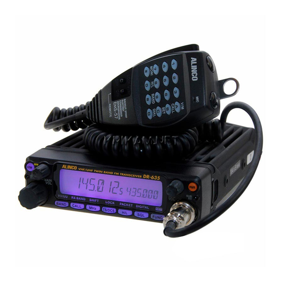
VHF/UHF FM TRANSCEIVER DR-635T/E Instruction Manual Thank you for purchasing your new Alinco transceiver. This instruction manual contains important safety and operating instructions. Please read this manual carefully before using the product and keep it for future reference.
Contents Channel name (Alphanumeric) registration function ..22 Before operating the transceiver ..... 3 CALL mode ............23 Attention ..............3 To recall a CALL channel ........23 To receive signals ..........23 Introduction ..........3 Monitor function ........... 24 Reverse function ..........
Page 4
AM receiver mode ..........41 Selective Communication ...... 42 Tone-squelch (CTCSS) and DCS ......42 DET setting ..........43 Digital voice communication (DR-635T only) .. 44 Special Functions ........45 THEFT ALARM ............ 45 To connect, set and operate ....45 How the alarm operates ......
Introduction Thank you very much for purchasing this excellent Alinco transceiver. Our products are ranked among the finest in the world. This radio has been manufactured with state of the art technology and it has been tested carefully at our factory. It is de- signed to operate to your satisfaction for many years under normal use.
New and Innovative Features Your new radio features some of the most advanced functions and reliable engineering available anywhere. The ALINCO design philosophy is focused on developing innova- tive usable features, including the following: • Full-duplex operation and Cross-band repeat function*.
The standard accessories may vary slightly depending on the version you have purchased. Please contact your local authorized Alinco dealer should you have any questions. ALINCO and authorized dealers are not responsible for any typographical errors there may be in this manual. Standard accessories may change without notice.
Use a regulated power supply capable of providing continuous current of 12A or more. Power supplies that do not meet those specifications may cause malfunction and/or damage to the radio and will void the warranty. Alinco offers excellent communication-grade power supplies as optional accessories. Please contact your local authorized Alinco dealer.
Initial Installation For a mobile station set up Location The transceiver may be installed in any position in your car, where the controls and microphone are easily accessible and it does not interfere with the safe operation of the vehicle or the performance of the set.
Initial Installation Front Panel The main unit can be set with either side facing up. This can facilitate your ability to hear the speaker clearly. Position the front panel as you prefer. Slide the front panel while keeping the tab pressed. Main unit Front panel Turn the front panel, being careful to keep the cable free from kinks.
Initial Installation External power control function Red: For connection with the ACC power supply Black: For connection with the ground(-) wire Black CN11 When installing, be SW11 sure the tube is placed in the slot. ACC external power supply control function is on WARNING: The connection of cables may involve certain knowledge about the ve- hicle into which the unit will be installed.
Initial Installation Power supply voltage display function After connecting the transceiver to a power supply, the supply voltage can be confirmed by press- ing the SQL key together with the FUNC key. The supply voltage to the transceiver is then seen on the display.
Part Names and Functions Front Panel MAIN TX/RX MAIN VV/UU RX BAND SHIFT LOCK PACKET DIGITAL BAND CALL TS/DCS FUNC •Primary Functions No. Key Function 1 PWR key Power turns ON/OFF whenever switch is pressed. 2 Main VOL knob Adjusts the volume level on the MAIN band. 3 Sub VOL knob Adjusts the volume level on the SUB band.
Part Names and Functions • Functions that can be activated while pressing the FUNC Key No. Key Function Reset to factory default settings. V/M/MW Erase the memory. BAND/VVUU Switches to the single band mode. CALL/RXBAND Accesses the clone function mode. 10 MHZ/SHIFT Switches to wide/narrow mode reception.
Part Names of Functions Display 10 11 12 13 14 15 MiLo Nar BUSY BUSY No. Key Function Appears when FUNC Key is pressed. 2 AM Appears during AM reception. 3 Mi Appears when transmission power is set to MID. 4 Lo Appears when transmission power is set to LOW.
Part Names and Functions Microphone EMS-53 (Standard)* *If the version you have purchased con- tained EMS-57 Multi- function microphone, please also refer page 55. No. Key Function 1 UP Increase the frequency, memory channel number, or setting value. 2 DOWN Decrease the frequency, memory channel number, or setting value.
Basic Operations Turning the unit on and off PWR key By pressing the PWR key the power is turned on. By pressing the PWR key again, the power is turned off. Refer page 9 for external power control. D SHIFT LOCK PACKET DIGITAL TS/DCS...
Basic Operations VFO mode VFO tuning is set as the default mode at the factory. VFO (variable frequency oscillator) allows you to change the fre- quency in accordance with the selected channel step as you VFO mode rotate the main dial or by using the UP/DOWN keys on the microphone.
Basic Operations Setting the channel step When the unit is in VFO mode, enter into the SET mode and select the channel step setting display. (Refer to page 26 to 28 for SET mode). Channel step setting display (default) The current channel step will be displayed. You can change the channel step as below by rotating the dial.
Basic Operations Shift Direction and Offset frequency setting Conventional repeaters are operated in the DUPLEX mode, which receives an incoming signal on one frequency and re-transmits on another. The difference between these two fre- quencies is called the offset frequency. The offset is variable between 0 to 99.995MHz on this unit.
Basic Operations Memory Mode This mode allows recalling and operating the preprogrammed frequency or setting. This unit pro- vides up to 200 memory channels (80 exclusive channels each for VHF and UHF, from 00 to 79CH and 40 common channels for VHF and UHF, from 100 to 139), 1 CALL channel each for V and U (C), 1 program-scan edge memory channel each for V and U (PL) (PH) and 1 VFO automatic program setting channel (AL) (AH).
Basic Operations How to program memory channel (s) Select a frequency to be programmed in the VFO mode and set the parameters as appropri- ate. Refer to the next page for programmable parameters. By pressing FUNC key, [F] and [Memory No.] icons will appear on the display.
Basic Operations Memory channel deleting Select the memory mode by pressing the V/M key. Memory Mode Select the desired memory channel number by rotating the main dial. The programmed memory channel has the memory number illuminated on the display. By pressing the M/W key together with the FUNC key while [F] icon is on, a beep will sound and the memory will be deleted.
Basic Operations Channel name (Alphanumeric) registration function The memory channels stored in the memory mode can be displayed with an alphanumeric tag instead of the default frequency display. There are 67 characters available including A-Z, 0-9. In the memory mode, select a channel to be programmed.
Basic Operations CALL mode This is a memory mode that allows the transceiver to quickly recall the assigned memory channel by simply pressing the CALL key, regardless of the current status of the unit. The default setting is 145.00MHz/433.00MHz, and one CALL channel is available on each band. To recall a CALL channel Select the desired VHF or UHF band by pressing the BAND key.
Basic Operations Monitor function A Monitor function is available to receive weaker signals. Press and hold SQL key for more than 1 second. Regardless of the level setting of the squelch, it will be opened and the Busy BUSY icon/RX lamp will turn on in the display. Press any key on the front panel to exit.
Basic Operations To transmit Set the transmission band to the MAIN side. Be sure that you are authorized to operate on the selected frequency. Check the system and monitor the frequency to make sure that you are not going to disturb any ongoing communications. TX lamp Press the PTT key on the microphone.
Parameter Setting Mode IMPORTANT: Please read the following pages thoroughly prior to changing any parameters. THE PARAMETERS CANNOT BE SET WITHOUT ENTERING THE SET MODE. By entering the Parameter Setting mode, some of the radio’s operating parameters can be changed to suit your application.
Parameter Setting Mode To use the parameter setting mode Press the FUNC key for more than 2 seconds to enter the parameter Setting mode. Select a menu by pressing the FUNC key and Default display the SQL key, or UP/DOWN keys on the micro- phone.
(20 kHz) NOTE: The default is as follows. • DR-635E [STEP 12.5] • DR-635T [STEP 5] Scan Type This is to select the scan resume condition. The TIMER set- ting allows the radio to resume scanning after 5 seconds, re- gardless of the signal receiving status.
Parameter Setting Mode (Refer page 27 for how to enter the setting mode.) Time-Out-Timer (TOT) The TOT feature is popular in repeater systems. It prohibits users from transmitting on the repeater after a certain period of time has elapsed. By setting this function and activating it according to the repeaters’...
Parameter Setting Mode (Refer page 27 for how to enter the setting mode.) APO-Auto Power OFF This feature will automatically shut off the transceiver. It is useful in mobile operation to avoid draining the car battery. If there is no activity or use of the radio, it will turn off automatically after 30 minutes followed by a beep sound.
Parameter Setting Mode (Refer page 27 for how to enter the setting mode.) Bell The bell informs you that you are being called by sounding a bell, and flashing the bell icon on the display. [BELL OFF] icon appears on the display. By rotating the main dial, the display changes as BELL OFF BELL ON...
Parameter Setting Mode (Refer page 27 for how to enter the setting mode.) TX display color This is to select the display illumination color during the trans- mission. The [TX-COL] appears on the display. By rotating the main dial, the display changes as shown on the right and the illumination color is changed.
Parameter Setting Mode (Refer page 27 for how to enter the setting mode.) Dimmer This is to provide better visibility of the display by dimming the display illumination in the dark. The [LAMP 4] icon appears on the display. By rotating the main dial, the display changes LAMP 1 LAMP 2 as below and the Dimmer setting is changed.
Parameter Setting Mode (Refer page 27 for how to enter the setting mode.) Transmission speed setting (In packet operation) This sets the data transmission speed in packet operation. [HB 1200] icon appears on the display. By rotating the main dial, the display changes HB 1200 HB 9600 as shown on the right and the setting is changed.
Useful functions Reception band switching This is to Select the receiving band. On the VHF side, FM broadcasting can be received. While in the VFO mode. After pressing the FUNC key, press the CALL key while [F] icon is on. On the VHF side, the band switches from 144MHz band to the FM broadcasting band.
Useful functions Single-band mode This is to use the unit as a single-band transceiver only for VHF or UHF, by eliminating the display on the SUB side. Press the BAND key while pressing and hold- ing the FUNC key. The display on the SUB side disappears and its function is temporarily suspended.
Useful functions SCANNING FUNCTION Use this function to automatically search for signals. 6 different scan types are available in the unit. In the parameter setting mode, choose the Timer mode or the Busy mode to determine the desired resuming condition. If the CTCSS(TSQ) squelch or DCS squelch is set, the audio can be heard only when the tone/code matches the incoming signal.
Useful functions •Memory Scan Scans all memory channels unless the Memory skip feature is selected for a given memory channel. Enter Memory mode. Sequence is the same as in VFO scan. Use UP/ DOWN keys for commands, otherwise press H/L key for more than 2 seconds. Range of Memory Scan Exclusive scanning for VHF/UHF: If scanning is started somewhere between memory...
Useful functions •Program Scan This is a type of VFO scan, which is done by setting the fre- Band edge H quency range of the VFO into the PH and PL channels, it only scans between those frequencies. When the PH and PL are set properly, up to 3 Program scan ranges will be available, which are L-PH, PL-PH and PH-H.
Useful functions •DCS scan Same as previous, but for DCS code search. While in the DCS setting, press the UP/DOWN key for more than 1 second but less than 2 sec- onds to start scanning. (It scans 105 DCS codes in order.) •...
Useful functions Narrow-band mode This feature is useful in areas where narrow band widths are in use. Press the MHz key together with the FUNC key. The [Nar] icon appears on the display to show the unit is in the Narrow mode. In the Narrow mode Repeat the same operation to return to the nor- mal mode.
Selective Communication Many repeaters require a CTCSS tone or a DCS encode setting as a “key” to access a repeater system, or a receiver using CTCSS or DCS squelch, so-called “selective-calling”. Sometimes, CTCSS or DCS decode features are used on the output of a repeater so they can be used to open a squelch.
Selective Communication DET setting If the DET mode in DCS operation is preferred, press the H/L key while the DCS code is displayed in the setting mode. Observe that a decimal point appears, then follow the remaining sequence to set the parameter and exit. DET on DCS function stands for Detect-Only mode.
Selective Communication Digital voice communication (DR-635T only) By installing an optional digital unit EJ-47U, digital voice communication becomes possible. Install EJ-47U to the connecter CN3 of the unit. Press the FUNC key, and then press the SQL key while the [F] icon is displayed.
Special Functions THEFT ALARM This alert uses a beep sound when the unit is about to be removed in an improper manner. This function is useful when the unit is installed in a vehicle. To connect, set and operate IMPORTANT: Be sure to connect the power cable directly to the car battery. The power cable of this unit requires voltage at all times to activate this function.
Special Functions Set SCR-ON in the setting mode. The [ * ] icon will appear on the display. TX lamp Turn OFF the unit. Alarm function is activated, the display will turn off and TX display lamp will start illuminat- MAIN MAIN TX/RX...
Special Functions Setting alarm starting time Choose this operation when a delay period is desired. TX lamp Enter the Parameter setting mode as described previously and select SCR-DLY. Follow the previous instruction to set. MAIN MAIN TX/RX VV/UU RX BAND SHIFT LOCK PACKET DIGITAL BAND...
Special Functions Cable Clone This feature will copy the programmed data and parameters in the master unit to slave units. 3.5 ø stereo-mini plug Master side Slave side Plug configuration (both for Master/Slave) DATA TX/RX Connection Make a cable using 3.5 mm stereo-mini plugs as shown above. Make a master unit by setting and programming it as desired.
Special Functions Setting on the Master side Press the CALL key with FUNC key pressed. CLONE will be displayed and the radio enters the clone mode. Press PTT. SD*** will be displayed and the master unit starts sending data to the slave unit. During transmission [PASS] will appear on the display when the data has been successfully transmitted.
Special Functions Packet Communication Packet communication is a high-speed data communication system transmitting a package of data generated through a personal computer. The use of Digi-peaters (relay stations) offers communica- tions with DX stations (distant stations). For packet communication, a personal computer, DSB-9 cable and the optional EJ-50U (TNC unit) are required in addition to this unit.
Special Functions Connect the EJ-50U with a personal computer. Connect the DSUB connecter on the rear panel and the serial port of a personal computer with a straight cable. RS-232C straight cable Personal computer IMPORTANT: Between the DSUB9 and a personal computer, use a 9-pin RS-232C straight cable (male-female).
Special Functions APRS Install the optional TNC unit EJ-50U and an external GPS receiver to operate in this mode. APRS (Automatic Packet/Position Reporting System) is program software registered as a trade- mark of Bob Bruninga, WB4APR. With this program, you may trace a mobile station on a map displayed by a computer.
Special Functions APRS operation For detailed information, please see a list of commands and the instruction manual of the EJ-50U. Boot up the terminal software on the PC, press Geolocating communication mode the FUNC key and press the H/L key while the [F] icon is on.
Special Functions TNC Clone This feature enables setting changes required for APRS function without connecting to a PC. Please use this feature when a setting change is desired while the APRS function is in operation. Setting changes are available for the call sign of your station, communication speed and data trans- mission time separation (Setting is made in setting mode).
Special Functions Remote Control Operation (EMS-57 Only) The transceiver can be controlled remotely by operating the DTMF keys on the microphone. Fre- quencies can also be entered directly through the key pads. LOCK DTMF No. Key Function OFF OFF Enter the remote command or the frequency. 1 DTMF Press LOCK to prevent the transceiver from accepting 2 LOCK...
Special Functions Entering a frequency directly Frequencies can be entered directly by pressing the numerical keys of the microphone. • Range of frequencies to be input 76.000 - 107.995MHz (WFM reception) 144.000 - 145.995MHz 430.000 - 439.995MHz Set the microphone DTMF/REMOTE switch to the REMOTE position. DTMF keys can be used to enter from the 100MHz digit.
BUSY All LCD segments IMPORTANT: While holding the FUNC key down, turn the power on. All segments of the LCD will be displayed, then default settings are displayed. Factory Default Settings DR-635T DR-635E MAIN band VFO frequency (VHF) 145.00MHz 145.00MHz (UHF) 445.00MHz...
Maintenance / Reference Troubleshooting Please check the list below before concluding that the transceiver is faulty. If a problem persists, reset the transceiver. This can sometimes correct erroneous operation. Problem Possible Causes Potential Solutions Power is on, nothing a. + and - polarities of power a.
• In case you are monitoring the 3 multiple of TX frequency, you may hear your voice from the unit but this is normal. Optional accessories • EMS-57 DTMF equipped microphone • EMS-53 Microphone (This comes standard with the DR-635T) (This comes standard with the DR-635E) • EJ-50U TNC unit...
Page 64
VHF/UHF FM MOBILE TRANSCEIVER 144.000-145.995MHz / 430.000-439.995MHz CE0336 This device is authorized for use in all EU and EFTA member states. An operator's license is required for this device. CAUTION: RF Hazard Warning. The electro-magnetic (radio Frequency) exposure level of this device may exceed the European standards of the hazard level when transmitting at the high-power setting while connected to a unity gain antenna at a distance of 63cm or less from the opera- tor.
Page 65
XBR (Crossband Repeater) Mode (for the DR-635T Only) This mode allows the DR-635T to operate like a repeater using both VHF and UHF bands. That is, when receiving a signal on one band, the DR635T automatically transmits the same signal on another band simultaneously.
Page 66
ALINCO,INC. Head Office: Shin-Dai building 9th Floor 2-6, 1-Chome, Dojimahama, Kita-ku, Osaka 530-0004, JAPAN Phone:+81-6-4797-2136 Fax:+81-6-4797-2157 E-mail:export@alinco.co.jp Printed in Japan Copyright Alinco,Inc. 2005 PS0488...
Need help?
Do you have a question about the DR-635T and is the answer not in the manual?
Questions and answers