
Related Manuals for Alinco DR 235 T


Summary of Contents for Alinco DR 235 T
- Page 1 Manual DR-235...
- Page 2 Copyright @ 2000 All rights reserved. No part of this document may be reproduced, copied, translated or transcribed in any form or by any means without the prior written permission of Alinco. Inc., Osaka, Japan. English Edition Printed in Japan.
- Page 4 CIRCUIT DESCRIPTION DR-235 1) Receiver System The receiver system is a double superheterodyne system with a 30.85 MHz first IF and a 455 kHz second 1. Front End The received signal at any frequency in the 216.000MHz to 279.995MHz range is passed through the low- pass filter (L116, L115, L114, L113, C204, C203, C202, C216 and C215) and tuning circuit (L105, L104 and D105, D104), and amplified by the RF amplifier (Q107).
- Page 5 and sounds is outputted from the speaker.) 6.AIR Band Reception T only If it is made air band receiving mode, IF signal is demodulated by AM decoder of IC106,and is output from pin13 as the AF signal. 7.WIDE/NARROW switching circuit The 2nd IF 455 kHz signal which passes through filter FL101 (wide) and FL102 (narrow) during narrow, changes its width using the width control switching IC103 and IC102.
- Page 6 compares the phase of the frequency from the VCO with that of the comparison frequency, 5 or 6.25kHz, which is obtained by the internal divider in IC501. 4. PLL Loop Filter Circuit If a phase difference is found in the phase comparison between the reference frequency and VCO output frequency, the charge pump output (pin 13) of IC501 generates a pulse signal, which is converted to DC voltage by the PLL loop filter and input to the varicap of the VCO unit for oscillation frequency control.
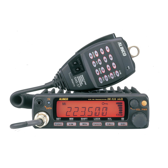
- Page 7 Primary Functions Power turns ON/OFF whenever power supply switch is pressed. V olume knob Adjusts the volume level. Dial Changes the frequency, memory channel and scan direction. FUNC/SET Sets in the function mode to access additional setting. V/M/MW Switches between VFO mode and memory mode. MHZ/SHIFT Changes the frequency in 1 MHz steps.
- Page 8 Antenna Connector Connection for 50 ohm coaxial cable and antenna. DSUB9 Connector Terminal where external TNC may be connected for packet use. With optional EJ-41U, connects internal TNC to the connector. External Speaker Terminal Terminal for market available external speaker. External Power jack Terminal for connecting optional EDC-37 for use with ignition key on/off function.
- Page 9 DISPLAY Appears when setting the squelch level. Appears when in memory mode Indicates the memory no. in memory mode .Decimal point Appears when setting the burglar alarm function. . Decimal point Appears when setting the decimal point of skip level. .
- Page 10 MICROPHONE DR-235T DR-235T (option) Function Increase the frequency, memory channel number, or setting value. Decrease the frequency, memory channel number, or setting DOWN value. Press the PTT(Push-To-Talk)key to transmit. DTMF DTMF tone keys. DTMF Switches DTMF mic key illumination ON/OFF. ON/OFF Lock Locks out the UP and DOWN keys.
Need help?
Do you have a question about the DR 235 T and is the answer not in the manual?
Questions and answers