Table of Contents
Advertisement
WARNING
Improper installation, adjustment, alteration, service
or maintenance can cause property damage, injury or
death, and could cause exposure to substances
which have been determined by various state
agencies to cause cancer, birth defects or other
reproductive harm. Read the installation, operating
and maintenance instructions thoroughly before
installing or servicing this equipment.
IMPORTANT
1. The use of this manual is specifically
intended for a qualified installation and
service agency. A qualified installation and
service agency must perform all installation
and service of these appliances.
2. SSD and SSH units contain the refrigerant
R-410A. Review the R-410A Material Safety
Data Sheet (MSDS) for hazards and first aid
measures.
3. Refrigerant charging should only be carried
out by an EPA-certified air conditioning
contractor.
This manual is the property of the owner.
Please be sure to leave it with the owner when you leave the job.
INSTALLATION AND SERVICE MANUAL
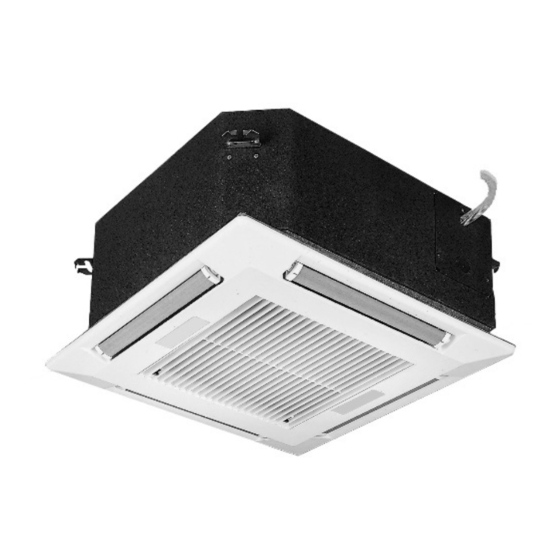
The SLIMLINE PERFORMER Ceiling Cassette
Models SSD, SSH and SCW
WARNING
This unit contains R-410A high pressure refrigerant.
Hazards exist that could result in personal injury or
death. Installation, maintenance, and service must only
be performed by an HVAC technician qualified in R-
410A refrigerant and using proper tools and equipment.
Due to much higher pressure of R-410A refrigerant, DO
NOT USE service equipment or tools designed for
refrigerants other than R410A.
Inspection upon Arrival
1.
Inspect unit upon arrival. In case of damage, report
immediately to transportation company and your local
factory sales representative.
2.
Check serial plate on unit to verify that the power supply
meets available electric power at the point of installation.
3.
Inspect unit received for conformance with description of
product ordered (including specifications where
applicable).
8-504.6
5H101548A2
February, 2014
Advertisement
Table of Contents

Related Manuals for Modine Manufacturing SSD


Summary of Contents for Modine Manufacturing SSD
- Page 1 A qualified installation and service agency must perform all installation and service of these appliances. 2. SSD and SSH units contain the refrigerant R-410A. Review the R-410A Material Safety Data Sheet (MSDS) for hazards and first aid measures.
-
Page 2: Table Of Contents
Exploded Unit Drawing & Parts List: SCW 08 & 12 CAUTION Exploded Unit Drawing & Parts List: SSD/SSH/SCW 18 - 42 Maintenance – Indoor Unit SSD and SSH units contain the refrigerant R-410A. Troubleshooting – Indoor Unit 23-26 Review the R-410A Material Safety Data Sheet Replacement Parts (MSDS) for hazards and first aid measures. -
Page 3: Si (Metric) Conversion Factors
11½” protect the fascia from dirt and damage, it should be returned to the box until it is ready to be installed. SCW 33, 36 & SSD/SSH 18 - 42 13½” Blank Off Pieces When branch ducting is to be used, polystyrene pieces for... - Page 4 28½” 31½” Secure the unit in position with locknuts and washers on both sides of the unit bracket. Ensure the threaded rod SSD/SSH/SCW 30, 33, 36 & 42 28½” 43½”” does not protrude more than 2” below the mounting bracket as shown in Figure 5.1.
-
Page 5: Installation
Threaded Rod < 2” Piping Installation – SSD and SSH Units CAUTION SSD and SSH units contain the refrigerant R-410A. Review the R-410A Material Safety Data Sheet Condensate Piping The unit is supplied with a 3/8" ID flexible hose for (MSDS) for hazards and first aid measures. - Page 6 INSTALLATION Figure 6.1 This equipment in its standard form is designed for an Hot/Chilled Water Coil Piping Installation electrical supply of 208-230V, 1Ph, 60Hz. When connection to a 115V, 1Ph, 60Hz supply is necessary, a factory mounted step up transformer must be fitted to the unit. Any damage to or failure of units caused by incorrect wiring of the units is not covered by warranty.
- Page 7 (SSD and SSH units only). through the four keyhole brackets on the fascia and then 4. All electrical connections (both power and control) are sliding the fascia sideways until it locks into position.
-
Page 8: Start-Up Procedure
START-UP PROCEDURE 7. Check the operation of the condensate pump by pouring Sequence of Operation 7-8 ounces of water down the pump outlet, switch the unit on, select cooling mode and the lowest possible Electro-Mechanical Controls: A 24V signal from the temperature set point then observe the water being thermostat to terminal G supplies power the blower motor(s), pumped from the unit. -
Page 9: Start-Up Sheet - Example
START UP SHEET – EXAMPLE Figure 9.1 Start Up Sheet – EXAMPLE 8-504.6... - Page 10 DIMENSIONS – SMALL CHASSIS Figure 10.1 Dimensions – Small Chassis: SCW 08 and SCW 12 25 3/16 CW Inlet CW Outlet HW Coil Inlet (Optional) HW Coil Outlet (Optional) Branch Duct Opening (x3) Fresh Air Intake (x2) Pump Inspection Port 25 3/16 Condensate Drain Control Panel...
- Page 11 DIMENSIONS – MEDIUM CHASSIS Figure 11.1 Dimensions – Medium Chassis: SCW 18 and SCW 20 CW Coil Inlet CW Coil Outlet HW Coil Inlet (Optional) HW Coil Outlet (Optional) Fresh Air Intake (x3) Branch Duct Opening (x4) Pump Inspection Port Condensate Drain Control Panel 10.
- Page 12 DIMENSIONS – LARGE CHASSIS Figure 12.1 Dimensions – Large Chassis: SCW 33 and SCW 36 CW Coil Inlet CW Coil Outlet HW Coil Inlet (Optional) HW Coil Outlet (Optional) Fresh Air Intake (x3) Branch Duct Opening (x4) Pump Inspection Port Condensate Drain Control Panel 10.
- Page 13 DIMENSIONS – MEDIUM CHASSIS Figure 13.1 Dimensions – Medium Chassis: SSD/SSH 18 and SSD/SSH 24 DX Suction Line 11/16 DX Liquid Line HW Coil Inlet (Optional) HW Coil Outlet (Optional) Fresh AIr Intake (x3) Branch Duct Opening (x4) Pump Inspection Port...
- Page 14 DIMENSIONS – LARGE CHASSIS Figure 14.1 Dimensions – Large Chassis: SSD/SSH 30, SSD/SSH 36 and SSD/SSH 42 1 1/8 DX Suction Line DX Liquid Line HW Coil Inlet (Optional) HW Coil Outlet (Optional) Fresh AIr Intake (x3) Branch Duct Opening (x4)
- Page 15 TECHNICAL DATA – DX COOLING ONLY AND HEAT PUMP UNITS Table 15.1 Technical Data – DX Cooling Only and Heat Pump Units Units SSD/SSH 18 SSD/SSH 24 SSD/SSH 30 SSD/SSH 36 SSD/SSH 42 Nominal Cooling Capacity (1) BTU/h 19200 23000...
-
Page 16: Dimensions
TECHNICAL DATA – CONDENSERS FOR DX COOLING ONLY UNITS Table 16.1 Technical Data – Condensers for DX Cooling Only Units Cassette Unit SSD 18 SSD 24 SSD 30 SSD 36 SSD 42 Condenser Model YCJD18 YCJD24 YCJD30 YCJD36 YCJD42 Units... - Page 17 TECHNICAL DATA – CONDENSERS FOR HEAT PUMP UNITS Table 17.1 Technical Data – Condensers for Heat Pump Units Cassette Unit SSH 18 SSH 24 SSH 30 SSH 36 SSH 42 Condenser Model YHJD18 YHJD24 YHJD30 YHJD36 YHJD42 Units Performance Nominal System Cooling Capacity BTU/h 18,000 24,000...
- Page 18 TECHNICAL DATA – CHILLED WATER UNITS Table 18.1 Technical Data – Chilled Water Units SCW08 SCW12 SCW 18 SCW 20 SCW 33 SCW 36 Units Nominal Cooling Capacity (1) BTU/h 6,601 11,091 17,592 19,087 29,722 35,258 Construction Material: Fascia High Impact Polystyrene Material: Chassis Galvanized Steel Color: Fascia...
-
Page 19: Electrical Data - Ceiling Cassettes
ELECTRICAL DATA – CEILING CASSETTES Table 19.1 Electrical Data – Ceiling Cassettes Performance (With Electric Heat) Performance (No Electric Heat) Nominal Capacity Supply Voltage Recommended Recommended (Digit 4,5) (Digit 6) FLA MCA Fuse Size FLA MCA Fuse Size A: 115/60/1 ‐ ‐ ‐ 0.7 0.9 15 J: 110/50/1 6.3 7.8 15 B: 208/60/1 08 and 12 Small Chassis ... -
Page 20: Exploded Unit Drawing & Parts List - Scw 08 & 12
EXPLODED UNIT DRAWING & PARTS LIST – SCW2/8 & SCW2/12 Figure 20.1 Exploded Unit Drawing & Parts List – SCW 08 & 12 Cassette Chassis Fan/Motor Assembly 17 Receiver (Microprocessor Only) Chilled Water Coil 10 Coil/Return Air Sensors 18 Terminal Rail, Relays & Timer (Micro & (Microprocessor Only) Electro- Mechanical Version) Electric Heater Element Assembly... -
Page 21: Exploded Unit Drawing & Parts List: Ssd/Ssh/Scw
EXPLODED UNIT DRAWING & PARTS LIST – SSD/SSH/SCW 18 - 42 Figure 21.1 Exploded Unit Drawing & Parts List – SSD/SSH/SCW 18 - 42 Cassette Chassis Vane Evaporator Coil Vane Motor Assembly Condensate Tray Filter Condensate Tray Support Fascia High Level Switch (Shown Inverted) -
Page 22: Maintenance - Indoor Unit
MAINTENANCE – INDOOR UNIT/DISASSEMBLY PROCEDURE MAINTENANCE – INDOOR UNIT Recommended Spares One complete set of air filters. WARNING DISASSEMBLY PROCEDURE Disconnect power supply before disassembly to prevent When servicing or repairing of this equipment, use only electrical shock and injury from moving parts. factory-approved service replacement parts. -
Page 23: Troubleshooting - Indoor Unit
TROUBLESHOOTING – INDOOR UNIT Table 23.1 Troubleshooting – Indoor Unit TROUBLE POSSIBLE CAUSE POSSIBLE REMEDY Red Alarm LED flashing Faulty float switch. See section “Condensate High Level” at 1 second intervals (Microprocessor units only) Fan Trip. See section “Fans Will Not Run” Indoor coil sensor failure. - Page 24 TROUBLESHOOTING – INDOOR UNIT Table 24.1 Troubleshooting – Indoor Unit TROUBLE POSSIBLE CAUSE POSSIBLE CAUSE Incorrect MODE setting. Check that the transmitter MODE is set to Cooling or No Cooling Auto Mode. (micro units only) Set point too high. Check the set point on the transmitter or wall mounted thermostat and adjust if necessary.
- Page 25 TROUBLESHOOTING – INDOOR UNIT Table 25.1 Troubleshooting – Indoor Unit TROUBLE POSSIBLE CAUSE POSSIBLE REMEDY Maximum pump lift exceeded. Check that the condensate pump head is no greater than Condensate High Level 30”. (See page 5 of this manual for installation guide) (micro units: red alarm LED will flash at one second intervals)
-
Page 26: Replacement Parts
TROUBLESHOOTING/REPLACEMENT PARTS MODEL NUMBER DESIGNATION/SERIAL PLATE Table 26.1 Troubleshooting – Indoor Unit (Continued) TROUBLE The electric heat circuit contains one automatic reset and one manual reset overheat cut- ELECTRIC OVERHEAT out protection switch for each electric heat element fitted to the unit. The cut-outs are wired in line with the main power flowing in each element and operate as described below. - Page 27 THIS PAGE INTENTIONALLY LEFT BLANK 8-504.6...
- Page 28 Burners High Intensity Infrared Units Sheet Metal Parts All Products Modine Manufacturing Company has a continuous product improvement program, and therefore reserves the right to change design and specifications without notice. Commercial Products Group Modine Manufacturing Company 1500 DeKoven Avenue Racine, WI 53403 Phone: 1.866.823.1631 (toll free)
Need help?
Do you have a question about the SSD and is the answer not in the manual?
Questions and answers