Table of Contents
Advertisement
Available languages
Available languages
Quick Links
AGD
MANUALE TECNICO
Aeroevaporatori a soffitto con refrigerante A2L
TECHNICAL MANUAL
A2L refrigerant ceiling unit coolers
BETRIEBSANLEITUNG
Deckenluftverdampfer mit Kältemittel A2L
MANUAL TECNICO
Aeroevaporadores de techo con refrigerante A2L
MANUEL TECHNIQUE
Evaporateurs plafonniers avec réfrigérant A2L
ТЕХНИЧЕСКОЕ РУКОВОДСТВО
Потолочные воздухоохладители с хладагентом A2L
Advertisement
Table of Contents

Subscribe to Our Youtube Channel
Related Manuals for Modine Manufacturing AGD2


Summary of Contents for Modine Manufacturing AGD2
- Page 1 MANUALE TECNICO Aeroevaporatori a soffitto con refrigerante A2L TECHNICAL MANUAL A2L refrigerant ceiling unit coolers BETRIEBSANLEITUNG Deckenluftverdampfer mit Kältemittel A2L MANUAL TECNICO Aeroevaporadores de techo con refrigerante A2L MANUEL TECHNIQUE Evaporateurs plafonniers avec réfrigérant A2L ТЕХНИЧЕСКОЕ РУКОВОДСТВО Потолочные воздухоохладители с хладагентом A2L...
-
Page 3: Table Of Contents
Indice - Istruzioni per l'uso originali Versione linguistica originale Index - Traduction des instructions originales 1. Importante 1. Important 2. Applicazioni 2. Applications 3. Identificazione 3. Identification 4. Ispezione - Stoccaggio 4. Inspection - Stockage 5. Movimentazione e installazione 5. Manutention et installation 6. -
Page 5: Importante
1. Importante Leggere attentamente e con attenzione tutte le informazioni contenute in questo manuale prima di togliere l’imballo, prima di procedere alla manipolazione, all’assemblaggio, al posizionamento, all’avviamento del modello e prima di qualsiasi intervento sull’unità. In caso di dubbi contattare Modine. Questo manuale è... -
Page 6: Applicazioni
3. Identificazione Per qualsiasi comunicazione, richiesta di assistenza o ricambi, fornire il nome del modello e il numero di serie riportati sulla targhetta dati: AGD2 MANUFACTURER: MODINE CIS ITALY S.R.L. VIA GIULIO LOCATELLI, 22 33050 POCENIA (UDINE) ITALY... -
Page 7: Ispezione - Stoccaggio
4. Ispezione - Stoccaggio Al ricevimento del modello controllare immediatamente il suo stato di integrità; contestare subito alla compagnia di trasporto qualsiasi eventuale danno. L’imballaggio viene fabbricato conformemente al modello, ad adeguati mezzi di trasporto e di movimentazione. Il modello deve essere immagazzinato nel suo imballo originale in un locale temperato e lontano dalle intemperie. Non sovrapporre all’imballo nessun altro materiale. -
Page 8: Condizioni Di Installazione
Assicurare un volume libero adeguato (circa il 30% del volume interno della cella) per una corretta circolazione dell’aria in aspirazione e scarico. Nel caso di più aeroevaporatori nella medesima cella frigorifera o sala di climatizzazione rispettare le distanze riportate nel disegno. Rispettare la distanza minima per togliere e inserire le resistenze. AGD2 > 1.2 m > 3 m... - Page 9 6 10 Particolari condizioni di installazione o funzionamento quali celle basse, travature a soffitto, stoccaggi eccessivi, impedimenti al getto e/o all’aspirazione dell’aria, formazione impropria di brina dovuta ad eccessiva immissione di umidità nella cella, possono influenzare negativamente le prestazioni dichiarate e creare difettosità nei modelli. 6 11 I modelli standard possono non essere adatti ad operare in tunnel o celle di abbattimento/surgelamento rapido.
-
Page 10: Caratteristiche Costruttive E Dimensionali
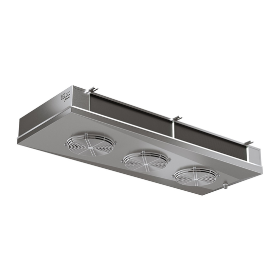
7. Caratteristiche costruttive e dimensionali AGD2 - Modello con ventola Ø230 mm Particolare di fissaggio resistenze L1 - Convogliatore L2 - Sgocciolatoio MF - Molla fermaresistenza RBB - Resistenza di bassa potenza nella batteria Modello 21E49R 21E49 21A49 22E49 22A49... - Page 11 AGD3 - Modello con ventola Ø315 mm (1) Per i modelli a 5 motori non è prevista questa quota C Particolare di fissaggio resistenze L1 - Convogliatore L2 - Sgocciolatoio LF - Listello fermaresistenza MF - Molla fermaresistenza RBB - Resistenza di bassa potenza nella batteria RSB - Resistenza di bassa potenza sullo sgocciolatoio interno Modello 311E3...
- Page 12 AGD3 - Modello con ventola Ø350 mm 1052 1007 (1) Per i modelli a 3 e 5 motori non è prevista questa quota C Particolare di fissaggio resistenze Modelli a 4 ranghi Modelli a 6 ranghi L1 - Convogliatore L2 - Sgocciolatoio LF - Listello fermaresistenza RBB - Resistenza di bassa potenza nella batteria RSB - Resistenza di bassa potenza sullo sgocciolatoio interno...
-
Page 13: Suggerimenti Per Un Corretto Accesso All'unità
8. Suggerimenti per un corretto accesso all’unità AGD2 Accesso Smontare il tubo di scarico condensa R1 in modo che non si crei intralcio al movimento del convogliatore L1. Svitare le viti di fissaggio “A” del convogliatore L1 (in alcuni modelli le viti sono presenti anche dal lato cerniere). - Page 14 AGD3 Accesso Smontare il tubo di scarico condensa R1 in modo che non crei intralcio al movimento del convogliatore L1. Togliere il deflettore L6 e svitare le viti di fissaggio “A” del convogliatore L1. 8 10 Accompagnare il convogliatore L1 fino alla posizione rappresentata in figura. 8 11 Nei modelli con motoventilatori Ø315 mm, al fine di intervenire anche sulle resistenze poste sotto la batteria, togliere gli sgocciolatoi interni L3 svitando le viti autofilettanti “B”.
-
Page 15: Schemi Elettrici
9. Schemi elettrici Schema di collegamento dei motoventilatori Attenzione. I motori sono dotati di termocontatti di protezione interni a riarmo automatico. Prima di utilizzare sistemi di regolazione del numero di giri dei motori verificare la compatibilità con i motori stessi, sistemi non compatibili pos- sono generare rumorosità... - Page 16 AGD2 - Modello con ventola Ø230 mm giallo-verde marrone motoventilatori scatola di derivazione (motoventilatori) 230V / 1 / 50-60Hz AGD3 - Modello con ventola Ø315 mm Part. "A" n. 2... n. 1 n. 2... n. 1 NOTA: È possibile la variazione del...
- Page 17 Per ridurre al minimo il rischio dovuto a contatti indiretti, si consiglia di collegare a terra l’unità, utilizzando il polo di terra (ove presente). Per altre informazioni fare riferimento agli schemi forniti assieme al modello. AGD2 - Modello con ventola Ø230 mm Modello AGD "ED"...
- Page 18 AGD3 - Modello con ventola Ø315 mm Modello AGD "ED" 311E3 312E3 313E3 314E3 315E3 316E3 Ø315 311E4 312E4 313E4 314E4 315E4 316E4 311E7 312E7 313E7 314E7 315E7 316E7 Ranghi Potenza totale 1500 2900 4400 5800 7200 8550 Collegamento 400V/3/50-60Hz PREDISPOSTO RBB3 RBB4 RBB1...
- Page 19 Collegamento 230V/1/50-60Hz da predisporre RBB3 RBB4 RBB1 RBB2 RSB1 RSB2 RBB - Resistenza elettrica di bassa potenza nella batteria RSB - Resistenza elettrica di bassa potenza sullo sgocciolatoio interno www.modine.com...
- Page 20 AGD3 - Modello con ventola Ø350 mm Modello AGD "ED" 351E3 361A3 352E3 362A3 353E3 363A3 354E3 364A3 Ø350 351E4 361A4 352E4 362A4 353E4 363A4 354E4 364A4 351E7 361A7 352E7 362A7 353E7 363A7 354E7 364A7 Ranghi Potenza totale 2000 2000 3600 3600 5600...
- Page 21 Collegamento 230V/3/50-60Hz da predisporre RBB3 RBB4 RBB6 RBB1 RBB2 RBB4 RSB1 RSB2 RBB2 RBB - Resistenza elettrica di bassa potenza nella batteria RSB - Resistenza elettrica di bassa potenza sullo sgocciolatoio interno Collegamento 230V/1/50-60Hz da predisporre RBB3 RBB4 RBB1 RBB2 RSB1 RSB2 RBB - Resistenza elettrica di...
-
Page 22: Controlli Da Eseguire Prima Della Messa In Funzione
10. Controlli da eseguire prima della messa in funzione Con sezionatore generale aperto e bloccato da lucchetto (posizione OFF): 10 1 Serraggio di tutti i collegamenti elettrici. 10.2 Livellamento e verifica della solidità della struttura portante. 10 3 Corretto fissaggio dei pannelli e dei componenti, prestare particolare attenzione al corretto fissaggio della griglia di protezione ventilatori. -
Page 23: Manutenzione
12. Manutenzione 12.1 I controlli, le ispezioni e la manutenzione devono essere fatti da personale specializzato autorizzato ad operare. 12.2 Durante le operazioni di manutenzione, riparazione e pulizia, utilizzare sempre dispositivi di protezione individuale (ad es. guanti sufficientemente resistenti ai rischi meccanici) per ridurre il rischio di lesioni in caso di contatto con i bordi affilati delle lamiere o con il pacco alettato. - Page 24 eventualmente adeguata copertura. 12.10.4 Aspirare eventualmente dal lato ingresso aria. 12.10.5 Dopo aver pulito il pacco alettato, eseguire un’analisi visiva per individuare eventuali residui di sporco o la presenza di alette danneggiate (ripetere se necessario l’operazione di pulizia). 12.11 Utilizzare esclusivamente pezzi di ricambio originali. Non aspettare che il componente sia completamente fuori uso, sostituzioni preventive possono migliorare notevolmente le prestazioni e prolungare la durata del modello.
- Page 25 12.22 Risoluzione dei problemi: Inconveniente Possibili cause Possibili soluzioni Verificare la rete di alimentazione Interruzione della rete di alimentazione fino alla scatola di collegamento (conduttori, sezionatori, regolatori, pressostati, ecc.) dei motoventilatori e ripristinare eventuali interruzioni Temperatura dell’aria in Verificare i dati di progetto in aspirazione dei particolar modo per quanto riguarda motoventilatori oltre i...
-
Page 26: Rischi Residui
13. Rischi residui 13 1 L’unità evidenzia rischi che non sono stati eliminati completamente dal punto di vista progettuale o con l’installazione di adeguate protezioni. In funzione di tali rischi si riporta quali DPI far utilizzare agli addetti o quali comportamenti e procedure sono da seguire. - Page 27 I collettori possono raggiungere basse temperature, evitare il contatto. Il flusso d'aria proveniente dai ventilatori può creare disagio al personale e danni alle cose. Si considera scorretto qualsiasi utilizzo diverso da quanto specificato nel presente manuale. Durante l’esercizio dell’apparecchiatura non sono ammessi altri tipi di lavori o attività che vanno considerati scorretti e che in generale possono comportare rischi per la sicurezza degli addetti e danni alle cose.
-
Page 28: Norme E Direttive Di Riferimento
I DPI utilizzati dovranno rispondere alle direttive di prodotto e dotati di marcatura CE (per il mercato europeo). Le definizioni delle fasi di vita dell’unità sono descritte nella seguente tabella. Fase Descrizione Trasporto Consiste nel trasferimento dell’unità da una località all’altra mediante l’utilizzo di un apposito mezzo Prevede il trasferimento dell’unità... -
Page 29: Dati Tecnici
15. Dati tecnici 15 1 Dati tecnici Codice modello Etichetta sull’unità Numero di serie Etichetta sull’unità Anno di produzione Etichetta sull’unità Pressione max PS Etichetta sull’unità Numero di progetto Documenti relativi a offerta / ordine Tipo di fluido Documenti relativi a offerta / ordine Volume interno Etichetta sull’unità... -
Page 30: Important
1. Important Carefully read all the information in this manual before removing the packaging, before handling, assembly, positioning, commissioning of the machine and before performing any work on the model. If in doubt contact Modine. This manual is an integral part of the product and must be kept for the entire life of the unit. Modine declines all responsibility for damage to persons and property caused by failure to follow all instructions contained in this manual. -
Page 31: Applications
3. Identification For any communication, request for assistance or spare parts, please provide the model name and serial number shown on the data plate: AGD2 MANUFACTURER: MODINE CIS ITALY S.R.L. VIA GIULIO LOCATELLI, 22... -
Page 32: Inspection - Storage
4. Inspection - Storage Upon receipt of the model immediately check its state of integrity; immediately dispute with the transport company any damage. The packaging is created according to the model, to the suitable means of transport and of handling. The model must be stored in its original packaging in a place that is protected and away from weathering. -
Page 33: Installation Conditions
For the installation of more than one unit in the same cold or airconditioned room it is necessary to observe the dimensions indicated in drawing. Keep the minimum distance so as to take out / insert the heaters. AGD2 > 1.2 m >... - Page 34 6 10 Particular conditions of installation or operation such as low or beamed rooms, overstorage, obstructed intake and exhaust air circulation and improper ice build-up due to excessive entry of humidity in room may negatively affect the stated performance and may cause defects. 6 11 Standard models may not be suitable for operation in tunnels or blast chilling/rapid freezing cells.
-
Page 35: Construction And Dimensional Features
7. Construction and dimensional features AGD2 - Ø230 mm fan diameter unit Positioning of electric heaters L1 - Fan shroud L2 - Drip tray MF - Heater clip RBB - Low power electric heater in coil Model 21E49R 21E49 21A49... - Page 36 AGD3 - Ø315 mm fan diameter unit (1) For 5-motor models this C dimension is not foreseen Positioning of electric heaters L1 - Fan shroud L2 - Drip tray LF - Heater fastening clip MF - Heater clip RBB - Low power electric heater in coil RSB - Low power electric heater on inner drip tray Model 311E3...
- Page 37 AGD3 - Ø350 mm fan diameter unit 1052 1007 (1) For 3 and 5-motor models this C dimension is not foreseen Positioning of electric heaters 4-row models 6-row models L1 - Fan shroud L2 - Drip tray LF - Heater fastening clip RBB - Low power electric heater in coil RSB - Low power electric heater on inner drip tray Model...
-
Page 38: Recommendations For A Proper Access To The Model
8. Recommendations for a proper access to the model AGD2 Access Disconnect drain connection R1 and position it as to avoid hampering with fan shroud L1. Unscrew the fixing screws "A" of the conveyor L1 (in some models the screws are also present on the hinge side). - Page 39 AGD3 Access Disconnect drain connection R1 and position it as to avoid hampering with fan shroud L1. Remove deflector L6 and unfasten screws “A” of fan shroud L1. 8 10 Bring fan shroud L1 to the position shown in drawing. 8 11 Models with Ø315 mm fan motors only.
-
Page 40: Wiring Diagrams
9. Wiring diagrams Motor-fan connection diagram Important. The motors are equipped with inner thermal protection with automatic reconnection. Before using motor speed control systems verify the compatibility with the motors. Non compatible systems may damage motors or incre- ase noise level; Modine will not be responsible for model performance with speed control systems. For fans equipped with thermal contacts (TK), these must be connected to the control circuit. - Page 41 AGD2 - Ø230 mm fan diameter unit yellow-green brown blue motorfans junction box (motorfans) 230V / 1 / 50-60Hz AGD3 - Ø315 mm fan diameter unit Det. "A" n. 2... n. 1 n. 2... n. 1 NOTE: It is possible to vary the number...
- Page 42 (where present). For further information please refer to the diagrams supplied with the model. AGD2 - Ø230 mm fan diameter unit Model AGD "ED"...
- Page 43 AGD3 - Ø315 mm fan diameter unit Model AGD "ED" 311E3 312E3 313E3 314E3 315E3 316E3 Ø315 311E4 312E4 313E4 314E4 315E4 316E4 311E7 312E7 313E7 314E7 315E7 316E7 Rows Total power 1500 2900 4400 5800 7200 8550 400V/3/50-60Hz Connection PRESET RBB3 RBB4 RBB1...
- Page 44 230V/1/50-60Hz Connection to set RBB3 RBB4 RBB1 RBB2 RSB1 RSB2 RBB - Low power heater in coil RSB - Low power heater on inner drip tray www.modine.com...
- Page 45 AGD3 - Ø350 mm fan diameter unit Model AGD "ED" 351E3 361A3 352E3 362A3 353E3 363A3 354E3 364A3 Ø350 351E4 361A4 352E4 362A4 353E4 363A4 354E4 364A4 351E7 361A7 352E7 362A7 353E7 363A7 354E7 364A7 Rows Total power 2000 2000 3600 3600 5600...
- Page 46 230V/3/50-60Hz Connection to set RBB3 RBB4 RBB6 RBB1 RBB2 RBB4 RSB1 RSB2 RBB2 RBB - Low power heater in coil RSB - Low power heater on inner drip tray 230V/1/50-60Hz Connection to set RBB3 RBB4 RBB1 RBB2 RSB1 RSB2 RBB - Low power heater in coil RSB - Low power heater on inner drip tray www.modine.com...
-
Page 47: Checks To Be Performed Before Start-Up
10. Checks to be performed before start-up With main switch open and padlocked (“0-OFF” position): 10 1 Tightening of all the electrical connections. 10.2 Levelling and checking the solidity of the supporting structure. 10 3 Correct fastening of panels and components, paying particular attention to the correct fastening of the fan guard grille. 10 4 Verification of spaces for maintenance. -
Page 48: Maintenance
12. Maintenance 12.1 Checks, inspections and maintenance must be carried out by specialised and authorised personnel. 12.2 During the operations of maintenance, repair and cleaning, always use personal protective equipment (e.g. gloves sufficiently resistant to mechanical hazards) to reduce the risk of injury in the event of contact with the sharp edges of the metal sheets or with the finned pack. - Page 49 12.10.5 After having cleaned the finned pack, perform a visual inspection to identify any dirt or the presence of fins that are damaged (repeat the cleaning operation if necessary). 12.11 Only use original spare parts. Do not wait until the component is completely worn out, preventive replacements can greatly improve performance and extend the life of the model.
- Page 50 12.22 Troubleshooting: Problem Possible causes Possible solutions Interruption of the electric power line Check electric power line up to fan (conductors, disconnecting switches, regulators, motor junction and reset pressure switches, etc) Suction air temperature Check project figures and of fan motors beyond data especially the working allowed limits temperatures...
-
Page 51: Residual Risks
13. Residual risks 13 1 The equipment presents a number of risks that have not been fully eliminated from the design point of view or through the installation of adequate protections. Based on such risks, it is reported which PPE should be used by the operators or which behaviours and procedures should be adopted. - Page 52 Headers can reach low temperatures, avoid contact. Airflow from fans can cause discomfort to personnel and damage to property. Any use other than that specified in this manual is considered incorrect. During operation of the equipment, no other types of work or activities are permitted that are to be considered as incorrect and that in general may entail risks for the safety of persons and damage to property.
-
Page 53: Reference Standards And Directives
The PPE used must comply with the directives of the product and bear the CE marking (for the European market). The definitions of the phases of life of the equipment are described in the following table. Phase Description Transportation It consists of transferring the equipment from one location to another through the use of suitable means. It consists of transferring the equipment from and on the means used for transportation and movements Handling within the plant. -
Page 54: Technical Data
15. Technical data 15 1 Technical data Model code Label on the unit Serial number Label on the unit Year of manufacture Label on the unit Max pressure PS Label on the unit Project number Documents relating to offer / order Fluid type Documents relating to offer / order Internal volume... -
Page 55: Wichtig
1. Wichtig Bitte lesen Sie sorgfältig alle Informationen in diesem Handbuch, bevor Sie die Verpackung entfernen, bevor Sie das Gerät handhaben, zusammenbauen, positionieren, in Betrieb nehmen und vor jedem Eingriff an der Maschine. Wenden Sie sich im Zweifelsfall an Modine. Dieses Handbuch ist ein integraler Bestandteil des Produkts und muss für die gesamte Lebensdauer des Geräts aufbewahrt werden. -
Page 56: Anwendungen
Luft gesenkt wird. 3. Identifizierung Für jegliche Kommunikation, Serviceanfragen oder Ersatzteile geben Sie bitte den Modellnamen und die Seriennummer an, die auf dem Typenschild angegeben sind: AGD2 MANUFACTURER: MODINE CIS ITALY S.R.L. VIA GIULIO LOCATELLI, 22 33050 POCENIA (UDINE) ITALY... -
Page 57: Inspektion - Lagerung
4. Inspektion - Lagerung Überprüfen Sie bei Erhalt des Modells sofort seinen Zustand; melden Sie eventuelle Schäden sofort dem Transportunternehmen. Die Verpackung wird entsprechend dem Modell und den geeigneten Transport- und Handhabungsmitteln hergestellt. Dieses Modell muss in der Originalverpackung in einem temperierten Raum und fern vom Witterungseinflüssen aufbewahrt werden. -
Page 58: Montagebedingungen
Luftzirkulation am Ein- und Auslass. Bei der Installation von mehreren Geräten im selben kalten oder klimatisierten Raum sind die in der Zeichnung angegebenen Maße zu beachten. Halten Sie den Mindestabstand ein, um die Heizgeräte herausnehmen/einsetzen zu können. AGD2 > 1.2 m > 3 m... - Page 59 6 10 Besondere Einbau- oder Betriebsbedingungen, wie niedrige Kühlzellen, Deckenträger, übermäßige Lagerung, Behinderungen des Luftstroms und/oder der Luftansaugung, übermäßige Reifbildung durch zu hohe Feuchtigkeit in der Kühlzelle können die angegebenen Leistungen negativ beeinflussen und Schäden an den Geräten hervorrufen. 6 11 Standardmodelle sind möglicherweise nicht für den Betrieb in Tunneln oder Schockkühl-/Schnellgefrierkammern geeignet. 6.12 Die Geräte sind mit Axialmotor-Ventilatoren ausgestattet, daher nicht für Kanalbetrieb oder zur Unterstützung zusätzlicher statischer Förderhöhen geeignet.
-
Page 60: Konstruktionseigenschaften Und Abmessungen
7. Konstruktionseigenschaften und Abmessungen AGD2 - Modell mit Flügeldurchmesser Ø230 mm Einzelheit der Heizstäbebefestigung L1 - Lüfterblech L2 - Tropfwanne MF - Heizstabbefestigungsleiste RBB - Niederleistungsheizstab im Wärmeaustauscher Modell 21E49R 21E49 21A49 22E49 22A49 23A49 24A49 25A49 Motorventilatoren n° x Ø mm... - Page 61 AGD3 - Modell mit Flügeldurchmesser Ø315 mm (1) Für Modelle mit 5 Motoren ist dieses C-Maß nicht vorgesehen. Einzelheit der Heizstäbebefestigung L1 - Lüfterblech L2 - Tropfwanne LF - Heizstabbefestigung sleiste MF - Heizstabbefestigungsleiste RBB - Niederleistungsheizstab im Wärmeaustauscher RSB - Niederleistungsheizstab in der inneren Tropfwanne Modell 311E3 312E3...
- Page 62 AGD3 - Modell mit Flügeldurchmesser Ø350 mm 1052 1007 (1) Für Modelle mit 3 und 5 Motoren ist dieses C-Maß nicht vorgesehen. Einzelheit der Heizstäbebefestigung 4-Rohrreihen Modelle 6-Rohrreihen Modelle L1 - Lüfterblech L2 - Tropfwanne LF - Heizstabbefestigung sleiste RBB - Niederleistungsheizstab im Wärmeaustauscher RSB - Niederleistungsheizstab in der inneren Tropfwanne Modell 351E3...
-
Page 63: Ratschläge Für Einen Korrekten Zugang Zum Gerät
8. Ratschläge für einen korrekten Zugang zum Gerät AGD2 Ausbau Den Tauwasserabfluß R1 abnehmen und so positionieren, dass er nicht mit die Lüfterblech L1 in Konflikt gerät. Lösen Sie die Befestigungsschrauben "A" die Lüfterblech L1 (bei einigen Modellen sind die Schrauben auch auf der Scharnierseite vorhanden). - Page 64 AGD3 Ausbau Den Tauwasserabfluß R1 abnehmen und so positionieren, dass er nicht mit der Lüfterblech L1 in Konflikt gerät. Umlenkblech L6 entfernen und Schrauben "A" der Lüfterblech L1 lösen. 8 10 Die Lüfterblech L1 in die in der Zeichnung gezeigte Position bringen. 8 11 Nur Modelle mit Lüftermotoren Ø315 mm.
-
Page 65: Elektrische Pläne
9. Elektrische Pläne Anschlußplan der Motorventilatoren Achtung. Die Motoren sind mit automatisch wiederaufrüstbaren Temperaturwächtern ausgestattet. Vor Anwendung von Drehzahlreglern die Eignung für die Motoren überprüfen; nicht verträgliche Systeme können Lärm und Schäden am Motor hervorrufen; Modine lehnt jede Verantwortung für mit Drehzahlreglern ausgestattete Geräte ab. Bei Ventila- toren, die mit Thermokontakten (TK) ausgestattet sind, müssen diese an den Steuerkreis angeschlossen werden. - Page 66 AGD2 - Modell mit Flügeldurchmesser Ø230 mm gelb-grün braun blau motorventilatoren abzweigdose (motorventilatoren) 230V / 1 / 50-60Hz AGD3 - Modell mit Flügeldurchmesser Ø315 mm Einz."A" n. 2... n. 1 n. 2... n. 1 gelb-grün Achtung: Drehzahländerungmittels zweckmäßigen Umschaltungs-syste- schwarz men möglich (nicht mitgeliefert).
- Page 67 Kabel und ihrem Typ. Um das Risiko eines indirekten Kontakts zu minimieren, ist es ratsam, das Gerät über den Erdun- gspol (sofern vorhanden) zu erden. Weitere Informationen finden Sie in den Diagrammen, die dem Modell beiliegen. AGD2 - Modell mit Flügeldurchmesser Ø230 mm Modell AGD "ED"...
- Page 68 AGD3 - Modell mit Flügeldurchmesser Ø315 mm Modell AGD "ED" 311E3 312E3 313E3 314E3 315E3 316E3 Ø315 311E4 312E4 313E4 314E4 315E4 316E4 311E7 312E7 313E7 314E7 315E7 316E7 Rohrreihen Gesamtleistung 1500 2900 4400 5800 7200 8550 Anschluß 400V/3/50-60Hz STANDARD RBB3 RBB4 RBB1...
- Page 69 Anschluß 230V/1/50-60Hz vorzubereiten RBB3 RBB4 RBB1 RBB2 RSB1 RSB2 RBB - Niederleistungsheizstab im Wärmeaustauscher RSB - Niederleistungsheizstab in der inneren Tropfwanne www.modine.com...
- Page 70 AGD3 - Modell mit Flügeldurchmesser Ø350 mm Modell AGD "ED" 351E3 361A3 352E3 362A3 353E3 363A3 354E3 364A3 Ø350 351E4 361A4 352E4 362A4 353E4 363A4 354E4 364A4 351E7 361A7 352E7 362A7 353E7 363A7 354E7 364A7 Rohrreihen Gesamtleistung 2000 2000 3600 3600 5600 5600...
- Page 71 Anschluß 230V/3/50-60Hz vorzubereiten RBB3 RBB4 RBB6 RBB1 RBB2 RBB4 RSB1 RSB2 RBB2 RBB - Niederleistungsheizstab im Wärmea- ustauscher RSB - Niederleistungsheizstab in der inne- ren Tropfwanne er heater in coil Anschluß 230V/1/50-60Hz vorzubereiten RBB3 RBB4 RBB1 RBB2 RSB1 RSB2 RBB - Niederleistungsheizstab im Wärmea- ustauscher RSB - Niederleistungsheizstab in der inne- ren Tropfwanne...
-
Page 72: Kontrollen Vor Inbetriebnahme
10. Kontrollen vor Inbetriebnahme Bei geöffnetem und mit Vorhängeschloss gesperrtem Hauptschalter (Stellung “0-OFF”): 10 1 Ziehen Sie alle elektrischen Anschlüsse fest. 10.2 Nivellierung und Überprüfung der Festigkeit der Tragkonstruktion. 10 3 Korrekte Befestigung der Platten und Komponenten. Achten Sie besonders auf die korrekte Befestigung des Lüfterschutzgitters. -
Page 73: Wartung
12. Wartung 12.1 Prüfungen, Inspektionen und Wartungen müssen von geschultem und autorisiertem Personal durchgeführt werden. 12.2 Bei Wartungs-, Reparatur- und Reinigungsarbeiten immer eine persönliche Schutzausrüstung (z. B. Handschuhe, die gegen mechanische Gefahren ausreichend beständig sind) verwenden, um die Verletzungsgefahr bei Kontakt mit den scharfen Kanten der Lüfterflügel oder mit der Klappe zu verringern. - Page 74 in einem Mindestabstand von 150 mm, der senkrecht auf das Lamellenpaket gerichtet ist, wobei ein Verbiegen oder eine Beschädigung der Lamellen und Rohre zu vermeiden ist, fügen Sie ggf. ein neutrales Reinigungsmittel hinzu (siehe die entsprechende Gebrauchsanweisung). Spülen und anschließend mit Druckluft gemäß Punkt 12.10.2 trocknen. Stellen Sie sicher, dass die elektrischen Komponenten nicht durch den Wasserstrahl beeinträchtigt werden, sorgen Sie ggf.
- Page 75 scharfe Kanten. 12.22 Fehlerbehebung: Auftretende Probleme Mögliche Ursachen Mögliche Lösungen Stromzufuhr bis zur Abweigdose Stromzufuhr unterbrochen des Motorventilator überprüfen und (Leitungen, Trennschalter, Regler, Drucowächter, usw.) eventuelle Unterbrechungen wieder herstellen Luftansaugtemperatur Überprüfen Sie die der Motorventilatoren Projektdaten, insbesondere die über der zulässigen Betriebstemperaturen Grenze Einschalten der...
-
Page 76: Restrisiko
13. Restrisiko 13 1 An der Vorrichtung können bestimmte Restrisiken verbleiben, welche in der Entwicklungsphase oder durch die Installation angemessener Schutzmaßnahmen nicht vollständig beseitigt wurden. Unter Anbetracht diese Risiken wird darauf hingewiesen, dass PSA von Mitarbeitern verwendet werden sollte oder dass bestimmte Verhaltensweisen und Verfahren zu befolgen sind. - Page 77 Verteiler können niedrige Temperaturen erreichen, vermeiden Sie den Kontakt. Der Luftstrom von Lüftern kann zu Unannehmlichkeiten für das Personal und zu Sachschäden führen. Jede andere Verwendung als in diesem Handbuch angegeben wird als unzulässig angesehen. Während des Betriebs der Ausrüstung sind andere Arbeiten oder Tätigkeiten, die als ungenau betrachtet werden und die im Allgemeinen eine Gefahr für die Sicherheit und den Sachschaden der Arbeitnehmer darstellen, nicht zulässig.
-
Page 78: Bezugsnormen Und Richtlinien
Die verwendete PSA muss den Produktrichtlinien entsprechen und das CE-Zeichen tragen (für den europäischen Mar- kt). Die Definitionen der Lebensphasen der Ausrüstung sind in der folgenden Tabelle beschrieben. Phase Beschreibung Darunter versteht man die Überstellung der Ausrüstung von einem Ort zum anderen mit einem speziel- Transport len Transportmittel. -
Page 79: Technische Daten
15. Technische Daten 15 1 Technische Daten Code Modell Etikett auf der Einheit Seriennummer Etikett auf der Einheit Herstellungsjahr Etikett auf der Einheit Maximaler Druck PS Etikett auf der Einheit Projektnummer Unterlagen in Bezug auf Angebot / Auftrag Flüssigkeitstyp Unterlagen in Bezug auf Angebot / Auftrag Innenvolumen Etikett auf der Einheit Gewicht... -
Page 80: Importante
1. Importante Leer atentamente y con atención todas las informaciones contenidas en este manual antes de quitar el embalaje, antes de realizar la manipulación, el montaje, la colocación, la puesta en marcha de la unidad y antes de cualquier intervención en el modelo, en caso de dudas comunicarse con Modine. -
Page 81: Aplicaciones
3. Identificación Para cualquier comunicación, pedido de asistencia o repuestos, suministrar el nombre del modelo y el número de serie colocado en la placa de datos: AGD2 MANUFACTURER: MODINE CIS ITALY S.R.L. VIA GIULIO LOCATELLI, 22 33050 POCENIA (UDINE) ITALY... -
Page 82: Inspección - Almacenamiento
4. Inspección - Almacenamiento Al recibir el modelo controlar inmediatamente su estado de integridad; reclamar rápidamente a la compañía de transporte cualquier daño eventual. El embalaje se fabrica en conformidad con el modelo, para adecuados medios de transporte y de movilización. El modelo se debe embalar en su embalaje original en un local templado y lejos de la intemperie. -
Page 83: Condiciones De Instalación
En el caso de varios aeroevaporadores en la misma cámara frigorífica o sala de aire acondicionado, respete las distancias indicadas en el dibujo. Respete la distancia mínima para extraer e introducir los elementos calefactores. AGD2 > 1.2 m > 3 m... - Page 84 6 10 Las condiciones especiales de instalación o funcionamiento, como celdas bajas, cerchas en el techo, almacenamiento excesivo, obstrucciones al flujo de aire y/o a la entrada, formación inadecuada de escarcha debido a la entrada excesiva de humedad en la celda, pueden afectar negativamente al rendimiento indicado y crear fallos en el modelo. 6 11 Los modelos estándar pueden no ser adecuados para el funcionamiento en túneles o cámaras de refrigeración/ congelación rápida.
-
Page 85: Características Constructivas Y Dimensionales
7. Características constructivas y dimensionales AGD2 - Modelo con hélice Ø230 mm Detalle de la posición de las resistencias L1 - Envolvente L2 - Bandeja desagüe MF - Resorte de resistencia RBB - Resistencias eléctricas de baja potencia en la bateria... - Page 86 AGD3 - Modelo con hélice Ø315 mm (1) Para los modelos con 5 motoventiladores no se prevé esta dimensión C Detalle de la posición de las resistencias L1 - Envolvente L2 - Bandeja desagüe LF - Tira aluminio soporte resistencia MF - Resorte de resistencia RBB - Resistencias eléctricas de baja potencia en la bateria RSB - Resistencias eléctricas de baja potencia en la bandeja de desagüe interna...
- Page 87 AGD3 - Modelo con hélice Ø350 mm 1052 1007 (1) Para los modelos con 3 y 5 motoventiladores no se prevé esta dimensión C Detalle de la posición de las resistencias Modelos de 4 filas Modelos de 6 filas L1 - Envolvente L2 - Bandeja desagüe LF - Tira aluminio soporte resistencia RBB - Resistencias eléctricas de baja potencia en la bateria...
-
Page 88: Sugerencias Para Un Correcto Acceso Al Modelo
8. Sugerencias para un correcto acceso al modelo AGD2 Acceso Retirar el tubo desagüe R1 para que no obstruya el movimiento del envolvente L1. Desenroscar los tornillos de fijación “A” del envolvente L1 (en algunos modelos los tornillos también están presentes en el lado de las bisagras). - Page 89 AGD3 Acceso Retirar el tubo desagüe R1 para que no obstruya el movimiento del envolvente L1. Retirar el deflector L6 y desatornillar los tornillos de fijación "A" del envolvente L1. 8 10 Colocar el envolvente L1 en la posición indicada en la figura. 8 11 En los modelos con motoventiladores de Ø315 mm, para poder trabajar también sobre las resistencias situadas debajo de la batería, retire las bandejas desagüe interiores L3 desatornillando los tornillos autoroscantes "B".
-
Page 90: Esquemas Eléctricos
9. Esquemas eléctricos Esquema de conexión motoventiladores Atención. Los motores van provistos de termocontactos de protección internos con rearme automático. Antes de utilizar sistemas de regulación del número de vueltas de los motores, verificar si son compatibles con los motores; sistemas no compatibles pueden causar rumorosidad y dañar los mismos;... - Page 91 AGD2 - Modelo con hélice Ø230 mm amarillo-verde marrón azul motoventiladores caja de conexión (motoventiladores) 230V / 1 / 50-60Hz AGD3 - Modelo con hélice Ø315 mm Detalle "A" n. 2... n. 1 n. 2... n. 1 NOTA: Es posible la variación del amarillo-verde número de vueltas del motor mediante...
- Page 92 Para minimizar el riesgo de contacto indirecto, es aconsejable conectar la unidad a tierra, utilizando la pértiga de tierra (si está presente). Para más información, consulte los diagramas suministrados con el modelo. AGD2 - Modelo con hélice Ø230 mm Modelo AGD "ED"...
- Page 93 AGD3 - Modelo con hélice Ø315 mm Modelo AGD "ED" 311E3 312E3 313E3 314E3 315E3 316E3 Ø315 311E4 312E4 313E4 314E4 315E4 316E4 311E7 312E7 313E7 314E7 315E7 316E7 Filas Potencia total 1500 2900 4400 5800 7200 8550 Conexión 400V/3/50-60 Hz CONECTADO DE FÁBRICA RBB3 RBB4 RBB1...
- Page 94 Conexión 230V/1/50-60 Hz posible ver sistema RBB3 RBB4 RBB1 RBB2 RSB1 RSB2 RBB - Resistencias eléctricas de baja potencia en la bateria RSB - Resistencias eléctricas de baja potencia en la bandeja de desagüe interna www.modine.com...
- Page 95 Modelo con hélice Ø350 mm Modelo AGD "ED" 351E3 361A3 352E3 362A3 353E3 363A3 354E3 364A3 Ø350 351E4 361A4 352E4 362A4 353E4 363A4 354E4 364A4 351E7 361A7 352E7 362A7 353E7 363A7 354E7 364A7 Filas Potencia total 2000 2000 3600 3600 5600 5600 7200...
- Page 96 Conexión 230V/3/50-60 Hz posible ver sistema RBB3 RBB4 RBB6 RBB1 RBB2 RBB4 RSB1 RSB2 RBB2 RBB - Resistencias eléctricas de baja potencia en la bateria RSB - Resistencias eléctricas de baja potencia en la bandeja de desagüe interna Conexión 230V/1/50-60 Hz posible ver sistema RBB3 RBB4 RBB1...
-
Page 97: Controles Antes De La Puesta En Funcionamiento
10. Controles antes de la puesta en funcionamiento Con el seccionador del interruptor principal abierto y con candado (posición “0-OFF”): 10 1 Ajuste de todas las conexiones eléctricas. 10.2 Nivelación y verificación de la solidez de la estructura de soporte. 10 3 Fijación correcta de los paneles y componentes. -
Page 98: Mantenimiento
12. Mantenimiento 12.1 Las revisiones, inspecciones y el mantenimiento deben ser realizados por personal cualificado y autorizado para ello. 12.2 Durante las operaciones de mantenimiento, reparación y limpieza, utilizar siempre equipos de protección individual (por ej.: guantes resistentes a los riesgos mecánicos) para reducir el riesgo de lesiones en caso de contacto con los bordes afilados de las chapas o con el paquete con aletas. - Page 99 de agua, eventualmente cubrir adecuadamente. 12.10.4 Si es necesario, aspirar por el lado de la entrada de aire. 12.10.5 Después de haber limpiado el paquete con aletas, hacer un análisis visual para detectar eventuales residuos de suciedad o la presencia de aletas dañadas (repetir si es necesario la operación de limpieza). 12.11 Utilizar únicamente piezas de recambio originales.
- Page 100 12.22 Solución de los problemas: Inconveniente Posible causa Posible solución Interución de la red de alimentación (conductores, Verificar la red de alimentación seccionadores, reguladores de press., etc.) hasta la caja de motores Excesiva temperatura Comprobar los datos del proyecto, del aire aspirada por sobretodo temperaturas de trabajo los motores Intervención de la...
-
Page 101: Riesgos Restantes
13. Riesgos restantes 13 1 El modelo evidencia riesgos que no han sido eliminados completamente desde el punto de vista proyectivo o con la instalación de protecciones adecuadas. En función de dichos riesgos se indican los EPI para que utilicen los encargados o los comportamientos y procedimientos que se deben realizar. - Page 102 Los colectores pueden alcanzar bajas temperaturas, evite el contacto. El flujo de aire de los ventiladores puede causar molestias al personal y daños a la propiedad. Se considera incorrecto todo uso diferente del especificado en el presente manual. Durante el funcionamiento del modelo no se admiten otros tipos de trabajos o actividades que se consideran incorrectas y que en general pueden causar riesgos para la seguridad de los encargados o daños a las cosas.
-
Page 103: Normas Y Directivas De Referencia
Los EPI utilizados deberán cumplir con las directivas del producto y estar dotados con la marca CE (para el mercado europeo). Las definiciones de las fases de vida útil del modelo se describen en la siguiente tabla. Fase Descripción Transporte Consiste en el traslado del modelo de una localidad a otra mediante el uso de un medio adecuado. -
Page 104: Datos Técnicos
15. Datos técnicos 15 1 Datos técnicos Código modelo Etiqueta en la unidad Número de serie Etiqueta en la unidad Año de producción Etiqueta en la unidad Presión máxima PS Etiqueta en la unidad Número de proyecto Documentos relativos a oferta / pedido Tipo de fluido Documentos relativos a oferta / pedido Volumen interno... -
Page 105: Important
1. Important Lire attentivement toutes les informations contenues dans ce manuel avant de retirer l’emballage, avant de procéder à la manipulation, à l’assemblage, au positionnement, à la mise en marche de la machine avant toute intervention sur le modèle; en cas de doute, contacter Modine. Ce manuel fait partie intégrante du produit et doit être conservé... -
Page 106: Applications
3. Identification Pour toute communication, demande d’assistance ou de pièces détachées, indiquer le nom du modèle et le numéro de série figurant sur la plaque signalétique: AGD2 MANUFACTURER: MODINE CIS ITALY S.R.L. VIA GIULIO LOCATELLI, 22... -
Page 107: Inspection - Stockage
4. Inspection - Stockage A la réception du modèle, contrôler immédiatement son intégrité; notifier immédiatement au transporteur les éventuels dommages. L’emballage est fabriqué conformément au modèle, à des moyens de transport et de manutention appropriés. Le modèle doit être stocké dans son emballage d’origine dans un local tempéré et à l’abri des intempéries. Ne pas placer aucun matériel sur l’emballage. -
Page 108: Conditions D'installation
Dans le cas de plusieurs aéroévaporateurs dans une même chambre froide ou une même salle de conditionnement d'air, respecter les distances indiquées sur le dessin. Respectez la distance minimale pour retirer et insérer les éléments chauffants. AGD2 > 1.2 m > 3 m... - Page 109 6 10 Des conditions particulières d’installation ou de fonctionnement, telles que des cellules basses, des fermes de plafond, un stockage excessif, des obstructions au flux et/ou à l’admission d’air, une formation de givre inappropriée due à un apport excessif d’humidité dans la cellule, peuvent affecter négativement les performances indiquées et créer des défaillances du modèle.
-
Page 110: Caractéristiques Constructives Et Dimensionnelles
7. Caractéristiques constructives et dimensionnelles AGD2 - Modèle avec hélice Ø230 mm Détail de positionnement résistances électriques de dégivrage L1 - Carénage de ventilation L2 - Egouttoir MF - Ressort fixation résistance RBB - Résistance de basse puissance dans la batterie Modèle... - Page 111 AGD3 - Modèle avec hélice Ø315 mm (1) Pour les modèles à 5 moteurs, cette cote C n’est pas prévue Détail de positionnement résistances électriques de dégivrage L1 - Carénage de ventilation L2 - Egouttoir LF - Tôle fixation résistance MF - Ressort fixation résistance RBB - Résistance de basse puissance dans la batterie RSB - Résistance de basse puissance sur l’égouttoir interne...
- Page 112 AGD3 - Modèle avec hélice Ø350 mm 1052 1007 (1) Pour les modèles à 3 et 5 moteurs, cette cote C n’est pas prévue Détail de positionnement résistances électriques de dégivrage Modèles à 4 nappes Modèles à 6 nappes L1 - Carénage de ventilation L2 - Egouttoir LF - Tôle fixation résistance RBB - Résistance de basse puissance dans la batterie...
-
Page 113: Instructions Pour Accéder À L'appareil
8. Instructions pour accéder à l’appareil AGD2 Retirez le goulot d’écoulement R1 de manière à ce qu'il ne gêne pas le mouvement du carénage de ventilation L1. Dévisser les vis de fixation "A" du carénage de ventilation L1 (dans certains modèles les vis sont également présentes côté... - Page 114 AGD3 Accès Retirez le goulot d’écoulement R1 de manière à ce qu'il ne gêne pas le mouvement du carénage de ventilation L1. Retirez le déflecteur L6 et dévissez les vis de fixation "A" du carénage de ventilation L1. 8 10 Déplacez le carénage de ventilation L1 dans la position indiquée sur la figure. 8 11 Dans les modèles avec moto-ventilateurs de Ø315 mm, afin de pouvoir travailler également sur les résistances situés sous la batterie, retirer les égouttoirs internes L3 en dévissant les vis autotaraudeuses "B".
-
Page 115: Schémas Électriques
9. Schémas électriques Schéma de connexion motoventilateurs Attention. Les moteurs sont dotés de thermocontacts de protection internes à réenclenchement automatique. Avant d’utiliser des systèmes de réglage du nombre de tours des moteurs, vérifier la compatibilité avec ces mêmes moteu- rs; des systèmes non compatibles peuvent générer des nuisances sonores ou des dommages aux moteurs mêmes; Modine n’assume aucune responsabilité... - Page 116 AGD2 - Modèle avec hélice Ø230 mm jaune-vert marron bleu motoventilateurs boîte de dérivation (motoventilateurs) 230V / 1 / 50-60Hz AGD3 - Modèle avec hélice Ø315 mm Part. "A" n. 2... n. 1 n. 2... n. 1 NOTE: Grâce à l’application d’oppor- jaune-vert tuns systèmes de commutation (non...
- Page 117 Pour minimiser le risque de contact indirect, il est conseillé de mettre l’appareil à la terre, en utilisant le poteau de terre (s’il y en a un). Pour de plus amples informations, veuillez vous référer aux schémas fournis avec le modèle. AGD2 - Modèle avec hélice Ø230 mm Modèle AGD "ED"...
- Page 118 AGD3 - Modèle avec hélice Ø315 mm Modèle AGD "ED" 311E3 312E3 313E3 314E3 315E3 316E3 Ø315 311E4 312E4 313E4 314E4 315E4 316E4 311E7 312E7 313E7 314E7 315E7 316E7 Nappes Puissance totale 1500 2900 4400 5800 7200 8550 Connexion 400V/3/50-60 Hz PRÉDISPOSÉE RBB3 RBB4 RBB1...
- Page 119 Connexion 230V/1/50-60 Hz à prédisposer RBB3 RBB4 RBB1 RBB2 RSB1 RSB2 RBB - Résistance de basse puissance dans la batterie RSB - Résistance de basse puissance sur l’égouttoir interne www.modine.com...
- Page 120 Modèle avec hélice Ø350 mm Modèle AGD "ED" 351E3 361A3 352E3 362A3 353E3 363A3 354E3 364A3 Ø350 351E4 361A4 352E4 362A4 353E4 363A4 354E4 364A4 351E7 361A7 352E7 362A7 353E7 363A7 354E7 364A7 Nappes Puissance totale 2000 2000 3600 3600 5600 5600 7200...
- Page 121 Connexion 230V/3/50-60 Hz à prédisposer RBB3 RBB4 RBB6 RBB1 RBB2 RBB4 RSB1 RSB2 RBB2 RBB - Résistance de basse puissance dans la batterie RSB - Résistance de basse puissance sur l’égouttoir interne Connexion 230V/1/50-60 Hz à prédisposer RBB3 RBB4 RBB1 RBB2 RSB1 RSB2...
-
Page 122: Contrôles À Effectuer Avant La Mise En Marche
10. Contrôles à effectuer avant la mise en marche Avec le sectionneur de l'interrupteur principal ouvert et cadenassé (position OFF): 10 1 Serrage de tous les branchements électriques. 10.2 Mise à niveau et vérification de la solidité de la structure porteuse. 10 3 Fixation correcte des panneaux et des composants, veiller particulièrement à... -
Page 123: Entretien/Maintenance
12. Entretien/maintenance 12.1 Les contrôles, les inspections et l'entretien doivent être effectués par du personnel qualifié et autorisé à le faire. 12.2 Durant les opérations d’entretien, réparation et nettoyage, toujours utiliser les équipements de protection individuelle (par ex.: gants suffisamment résistants aux risques mécaniques) pour réduire le risques de lésions en cas de contact avec les bords affilés des tôles ou avec les ailettes. - Page 124 nettoyant neutre le cas échéant (voir le mode d'emploi correspondant). Rincer puis sécher avec de l’air comprimé, comme indiqué au point 12.10.2. S’assurer que les composants électriques ne soient pas touchés par le jet d’eau; couvrir éventuellement. 12.10.4 Aspirer éventuellement du côté entrée d’air. 12.10.5 Après avoir nettoyé...
- Page 125 12.22 Résolution des problèmes: Problème Causes possibles Solutions possibles Vérifier le réseau d’alimentation Interruption du réseau d’alimentation (conducteurs, jusqu’à la boîte de branchement sectionneurs, régulateurs, pressostats, etc.) des motoventilateurs et rétabilir les éventuelles interruptions Température de l’air en aspiration des Vérifier les données de projet en motoventilateurs particulier en ce qui concerne les...
-
Page 126: Risques Résiduels
13. Risques résiduels 13 1 L’équipement comporte des risques qui n’ont pas été totalement éliminés d’un point de vue de conception ou avec l’installation de protection adéquates. En fonction de ces risques, voici les EPI à faire utiliser par les personnes préposées ou les comportements et procédures à... - Page 127 Les collecteurs peuvent atteindre des températures basses, évitez tout contact. Le flux d’air provenant des ventilateurs peut causer de l’inconfort au personnel et des dommages aux biens. Toute utilisation différente de l’utilisation spécifiée dans ce manuel est considérée incorrecte. Durant le fonctionnement de l’équipement, aucun type de travaux ou d’activités, qui doivent être considérés comme in- corrects et qui en général peuvent comporter des risques pour la sécurité...
-
Page 128: Normes Et Directives De Référence
Les EPI utilisés devront respecter les directives du produit et être dotés du marquage CE (pour le marché européen). Les définitions des phases de vie de l’équipement sont décrites dans le tableau suivant. Phase Description Transport Consiste à transférer l’équipement d’une localité à l’autre à l’aide d’un véhicule dédié. Prévoit le déplacement de l’équipement par et sur le véhicule utilisé... -
Page 129: Données Techniques
15. Données techniques 15 1 Données techniques Référence modèle Etiquette sur l’unité Numéro de série Etiquette sur l’unité Année de production Etiquette sur l’unité Pression maximale PS Etiquette sur l’unité Numéro de projet Documents relatifs à l’offre / la commande Type de fluide Documents relatifs à... -
Page 130: Важно
1. Важно Внимательно и тщательно прочтите всю информацию, содержащуюся в настоящем руководствеперед снятием упаковки, началом работ по сборке, размещению, запуску машины и перед любым вмешательством, в случае сомнений обратитесь в компанию Modine. Настоящее руководство является неотъемлимой частью продукта и должно храниться на протяжении всей службы... -
Page 131: Использование
испарение жидкости, протекающей внутри трубок, с последующим поглощением тепла и понижением температуры выходящего воздуха. 3. Идентификация При любых контактах, заявках на обслуживание или замену деталей, указывайте наименование модели и серийный номер, указанные на табличке с данными: AGD2 MANUFACTURER: MODINE CIS ITALY S.R.L. VIA GIULIO LOCATELLI, 22 33050 POCENIA (UDINE) ITALY... -
Page 132: Проверка - Хранение
4. Проверка - Хранение При получении модели сразу проверить ее на целостность; немедленно уведомить транспортную компанию о любых повреждениях. Упаковка изготавливается в соответствии с моделью, вместе с соответствующими средствами транспортировки и перемещения. Модель должна храниться в оригинальной упаковке и в помещении с умеренным климатом и вдали от неблагоприятных... -
Page 133: Условия Установки
циркуляции воздуха на впуске и выпуске. В случае установки нескольких испарителей aero в одной холодильной камере или помещении для кондиционирования воздуха соблюдайте расстояния, указанные на чертеже. Соблюдайте минимальное расстояние для снятия и установки нагревательных элементов. AGD2 > 1.2 m > 3 m... - Page 134 6 10 Особые условия установки или эксплуатации, такие как низкие ячейки, потолочные балки, чрезмерное хранение, препятствия для струи и / или забора воздуха, неправильное образование инея из-за чрезмерного попадания влаги в ячейку, возможность введения трансплантата в ячейку создают дефекты в моделях. 6 11 Стандартные...
-
Page 135: Конструкция И Габаритные Характеристики
7. Конструкция и габаритные характеристики AGD2 - Модель с крыльчаткой Ø230 mm Расположением электрических ТЭНов оттайки L1 - Конвейер L2 - Каплеуловитель MF - Пружина фиксации тэнов RBB - Низкое электрическое сопротивление в теплообменнике Mодель 21E49R 21E49 21A49 22E49 22A49... - Page 136 AGD3 - Модель с крыльчаткой Ø315 mm (1) Для 5-двигательных моделей такой квоты нет C Расположением электрических ТЭНов оттайки L1 - Воздухонаправляющая пластина L2 - Каплеуловитель LF - Планка фиксации ТЭНов MF - Пружина фиксации ТЭНов RBB - Низкое электрическое сопротивление в теплообменнике RSB - Электронагреватель...
- Page 137 AGD3 - Модель с крыльчаткой Ø350 mm 1052 1007 (1) Для 3- и 5-двигательных моделей такой квоты нет C Расположением электрических ТЭНов оттайки 4-рядные модели 6-рядные модели L1 - Воздухонаправляющая пластина L2 - Каплеуловитель LF - Планка фиксации ТЭНов RBB - Низкое электрическое сопротивление в теплообменнике RSB - Электронагреватель...
-
Page 138: Рекомендации По Корректному Доступу К Аппарату
8. Рекомендации по корректному доступу к аппарату AGD2 Доступ Снимите трубку слива конденсата R1 так, чтобы она не препятствовала движению конвейера L1. Отвинтите крепежные винты «А» конвейера L1 (в некоторых моделях винты имеются также со стороны петель). Переместите конвейер L1 в положение, показанное на рисунке. - Page 139 AGD3 Доступ Снимите трубку слива конденсата R1 так, чтобы она не препятствовала движению конвейера L1. Снимите дефлектор L6 и открутите крепежные винты "A" конвейера L1. 8 10 Переместите конвейер L1 в положение, показанное на рисунке. 8 11 В моделях с моторизованными вентиляторами Ø315 мм, для того чтобы также работать с нагревательными элементами, расположенными...
-
Page 140: Схемы Подключения
9. Схемы подключения Схема подключения мотовентиляторов Внимание. Двигатели оснащены встроенными термоконтактами тепловой защиты с автоматической перезагрузкой.Перед использованием системы регулирования числа оборотов двигателей проверьте совместимость с самими двигателями, несовместимые системы могут создавать шумы и повреждения; Modine не несет никакой ответственности по производительности моделей, оснащенных системами управления. Для вентиляторов, оснащенных... - Page 141 AGD2 - Модель с крыльчаткой Ø230 mm желто-зеленый коричневый синий электровентиляторы распределительные коробки (электровентиляторы) 230V / 1 / 50-60Hz AGD3 - Модель с крыльчаткой Ø315 mm Часть. "A" n. 2... n. 1 n. 2... n. 1 ПРИМЕЧАНИЕ: Можно изменить желтый-зеленый...
- Page 142 способа прокладки, длины кабелей и их типа. Для минимизации риска непрямого прикосновения рекомендуется заземлить устройство с помощью заземляющего полюса (если таковой имеется). Дополнительную информацию см. на поставляемых с моделью диаграммах. AGD2 - Модель с крыльчаткой Ø230 mm Mодель AGD "ED"...
- Page 143 AGD3 - Модель с крыльчаткой Ø315 mm Mодель AGD "ED" 311E3 312E3 313E3 314E3 315E3 316E3 Ø315 311E4 312E4 313E4 314E4 315E4 316E4 311E7 312E7 313E7 314E7 315E7 316E7 Ряды Общая мощность 1500 2900 4400 5800 7200 8550 Соединение 400V/3/50-60Hz ГОТОВО К ИСПОЛЬЗОВАНИЮ RBB3 RBB4 RBB1...
- Page 144 Соединение 230V/1/50-60Hz необходима предварительная подготовка RBB3 RBB4 RBB1 RBB2 RSB1 RSB2 RBB - Низкое электрическое сопротивление в теплообменнике RSB - Электронагреватель малой мощности на внутреннем поддоне для сбора капель www.modine.com...
- Page 145 AGD3 - Модель с крыльчаткой Ø350 mm Mодель AGD "ED" 351E3 361A3 352E3 362A3 353E3 363A3 354E3 364A3 Ø350 351E4 361A4 352E4 362A4 353E4 363A4 354E4 364A4 351E7 361A7 352E7 362A7 353E7 363A7 354E7 364A7 Ряды Общая мощность 2000 2000 3600 3600 5600...
- Page 146 Соединение 230V/3/50-60Hz необходима предварительная подготовка RBB3 RBB4 RBB6 RBB1 RBB2 RBB4 RSB1 RSB2 RBB2 RBB - Низкое электрическое сопротивление в теплообменнике RSB - Электронагреватель малой мощности на внутреннем поддоне для сбора капель Соединение 230V/1/50-60Hz необходима предварительная подготовка RBB3 RBB4 RBB1 RBB2 RSB1 RSB2...
-
Page 147: Контроль Перед Вводом В Эксплуатацию
10. Контроль перед вводом в эксплуатацию При открытом и запертом на висячий замок главном выключателе (положение “0-OFF”): 10 1 Правильность затяжки всех электрических соединений. 10.2 Выравнивание и проверка прочности несущей конструкции. 10 3 Правильное крепление панелей и компонентов, обратите особое внимание на правильное крепление защитной решетки... -
Page 148: Техобслуживание
12. Техобслуживание 12.1 Проверки, осмотры и техническое обслуживание должны выполняться уполномоченным специализированным персоналом. 12.2 Во время технического обслуживания, ремонта и очистки всегда используйте средства индивидуальной защиты (например, перчатки, достаточно устойчивые к механическим воздействиям), чтобы снизить риск получения травмы в случае контакта с острыми краями листового металла или с ребристым пакетом. 12.3 Никогда... - Page 149 расстоянии 150 мм, направленную перпендикулярно на ребристую поверхность, избегая загибания или повреждений лопаток и труб, при необходимости добавьте нейтральное моющее средство. Смыть, а затем высушить с помощью сжатого воздуха, как указано в пункте 12.10.2. Убедиться, что электрические компоненты не подвергаются воздействию струи воды, и при необходимости, обеспечить достаточное покрытие. 12.10.4 При...
- Page 150 12.22 Решение проблем: Возможные решения по Неполадка Возможные причины устранению Проверьте сеть питания до коробки соединения Размыкание питающей сети (проводники, мотовентиляторов и выключатели, регуляторы, реле давления, и т.п.) восстановито возможные размыкания Температура воздуха аспирации Проверьте проектные данные, мотовентиляторов особенно в отношении рабочих за...
-
Page 151: Остаточные Риски
13. Остаточные риски 13 1 Модель подчеркивает риски, которые не были полностью устранены с точки зрения проектирования или с помощью установки адекватных средств защиты. На основе этих рисков сообщается, какие СИЗ должны использоваться сотрудниками или какие действия и процедуры должны соблюдаться. На... - Page 152 Коллекторы могут достигать низких температур, избегайте контакта. Поток воздуха от вентиляторов может создать дискомфорт для персонала и нанести материальный ущерб. Любое использование, отличное от указанного в данном руководстве, считается ненадлежащим. Во время работы оборудования не допускаются никакие другие виды работ или деятельности, которые считаются...
-
Page 153: Справочные Стандарты И Директивы
Используемые СИЗ должны соответствовать директивам по продукции и иметь маркировку CE (для европейского рынка). Определения этапов жизни устройства описаны в следующей таблице. Этап Описание Она заключается в перемещении устройства из одного места в другое с помощью Транспортировка соответствующего транспортного средства. Она... -
Page 154: Технические Данные
15. Технические Данные 15 1 Технические Данные Код модели Этикетка устройства Номер серии Этикетка устройства Год производства Этикетка устройства Максимальное давление PS Этикетка устройства Номер проекта Документы, относящиеся к предложению/заказу Тип жидкости Документы, относящиеся к предложению/заказу Общий объем Этикетка устройства Вес... -
Page 155: Declaration Of Incorporation - Warranties
n a s c o sto www.modine.com... - Page 156 Garanzie Tutte le informazioni tecniche presenti in questa edizione sono basate su prove che riteniamo ampie e attendibili, ma che non possono essere riferite a tutta la casistica dei possibili impieghi.Pertanto, l’acqui- rente deve accertare l’idoneità del prodotto all’uso per il quale intende destinarlo, assumendo ogni responsabilità derivante dall’utilizzo dello stesso. La società venditrice, su richiesta dell’acquirente, si renderà disponibile fornendo tutte le informazioni utili per il migliore utilizzo dei suoi prodotti.
- Page 157 www.modine.com...
- Page 158 www.modine.com...
- Page 159 www.modine.com...
- Page 160 Manufacturer: Modine CIS Italy S.r.l. 33050 Pocenia - Udine - Italy Via Giulio Locatelli, 22 Tel. +39 0432.772.001 Fax +39 0432.779.594 www.modine.com AGDM2204A01P_M MN2634125...
Need help?
Do you have a question about the AGD2 and is the answer not in the manual?
Questions and answers