
Related Manuals for Modine Manufacturing ECO GSE31AH4


Summary of Contents for Modine Manufacturing ECO GSE31AH4
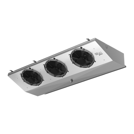
- Page 1 MANUALE TECNICO Aeroevaporatori a soffitto TECHNICAL MANUAL Ceiling unit coolers BETRIEBSANLEITUNG Deckenluftverdampfer MANUAL TECNICO Aeroevaporadores de techo MANUEL TECHNIQUE Evaporateurs plafonniers ТЕХНИЧЕСКОЕ РУКОВОДСТВО Потолочные воздухоохладители...
- Page 3 Indice - Istruzioni per l'uso originali Versione linguistica originale Déclaration d’incorporation – Garanties 1. Importante ....... . . 5 1.
- Page 5 15. Dati tecnici 15.1 Dati tecnici Codice modello Etichetta sull’unità Numero di serie Etichetta sull’unità Anno di produzione Etichetta sull’unità Pressione max PS Etichetta sull’unità Numero di progetto Documenti relativi a offerta / ordine Tipo di fluido Documenti relativi a offerta / ordine Volume interno Etichetta sull’unità...
- Page 6 1. Important Carefully read all the information in this manual before removing the packaging, before handling, assembling, positioning, commissioning of the machine and before performing any work on the model. If in doubt contact Modine. This manual is an integral part of the product and must be kept for the entire life of the unit. Modine declines all responsibility for damage to persons and property caused by failure to follow all instructions contained in this manual.
- Page 7 2. Applications The unit must not be put into service until the machine to which it will be incorporated has been declared in conformity with the Machinery Directive 2006/42/CE, see “Declaration of Incorporation” page 101. The unit is defined as “Partly completed machinery”.
- Page 8 4. Inspection - Storage Upon receipt of the model immediately check its state of integrity; immediately dispute with the transport company any damage. The packaging is created according to the model, to the suitable means of transport and of handling. The model must be stored in its original packaging in a place that is protected and away from weathering.
- Page 9 6. Installation conditions The model described in this manual is a component of a system and must be installed by authorised personnel only. Access to the unit for any type of intervention must be reserved to personnel qualified to operate the system, in accordance with the regulations in force.
- Page 10 6.23 When installing external control devices, check their compatibility with the electrical characteristics of the unit. 6.24 For installations at height, use elevating platforms, scaffolding or trestles. 6.25 If the unit is equipped with an electric defrosting device with resistors (connections cabled in a thermoplastic junction box), define the number and frequency of the switch-ons of the resistors and periodically check their functionality.
- Page 11 7. Construction and dimensional features Positioning of electric heaters Fin spacing 4mm Fin spacing 7mm L1 - Fan shroud RBA - High power electric heater in coil L2 - Drip tray RBB - Low power electric heater in coil LF - Heater fastening clip RSA - High power electric heater on inner drip tray Model 31AH4...
- Page 12 8. Recommendations for a proper access to the model Access Remove drain connection R1 and ensure that it does not hamper with the handling of the fan shroud L1. Unscrew the fixing screws D of the fan shroud L1 to the internal drip tray L3; unscrew the fixing screws C from inner side panels L2, remove baffle L4 and bring fan shroud L1 to the position shown in the figure.
- Page 13 9. Wiring diagrams Motor-fan connection diagram Important. The motors are equipped with inner thermal protection with automatic reconnection. Before using motor speed control systems verify the compatibility with the motors. Non compatible systems may damage motors or incre- ase noise level; Modine will not be responsible for model performance with speed control systems. For fans equipped with thermal contacts (TK), these must be connected to the control circuit.
- Page 14 AH4 ED, 6 Rows, fin spacing 4mm Connection Connection Connection 400V/3/50-60Hz STANDARD 230V/1/50-60Hz to be set 230V/3/50-60Hz to be set BL7 ED, 8 Rows, fin spacing 7mm Connection Connection Connection 400V/3/50-60Hz STANDARD 230V/1/50-60Hz to be set 230V/3/50-60Hz to be set RBA - High power electric heater in coil RBB - Low power electric heater in coil RSA - High power electric heater on inner drip tray...
- Page 15 10. Checks to be performed before start-up With main switch open and padlocked (“0-OFF” position): 10.1 Tightening of all the electrical connections. 10.2 Levelling and checking the solidity of the supporting structure. 10.3 Correct fastening of panels and components, paying particular attention to the correct fastening of the fan guard grille. 10.4 Verification of spaces for maintenance.
- Page 16 12.10 Cleaning of the finned pack: Figure 5 12.10.1 Place the main switch in the “OFF” position and wait until all the fans have stopped rotating. Lower the conveyor (ref. Chapter 8). Protect the motor fans and electrical connections with waterproof covers and/or panels. If necessary, remove the motor fans and their grilles by unscrewing the fixing screws.
- Page 17 12.20 Troubleshooting: Problem Possible causes Possible solutions Interruption of the electric power line Check electric power line up to fan (conductors, disconnecting switches, regulators, motor junction and reset pressure switches, etc) Suction air temperature Check project figures and of fan motors beyond data especially the working allowed limits temperatures...
- Page 18 13. Residual risks 13.1 The equipment presents a number of risks that have not been fully eliminated from the design point of view or through the installation of adequate protections. Based on such risks, it is reported which PPE should be used by the operators or which behaviours and procedures should be adopted.
- Page 19 Headers can reach low temperatures, avoid contact. Airflow from fans can cause discomfort to personnel and damage to property. Any use other than that specified in this manual is considered incorrect. During operation of the equipment, no other types of work or activities are permitted that are to be considered as incorrect and that in general may entail risks for the safety of persons and damage to property.
- Page 20 The PPE used must comply with the directives of the product and bear the CE marking (for the European market). The definitions of the phases of life of the equipment are described in the following table. Phase Description Transportation It consists of transferring the equipment from one location to another through the use of suitable means. It consists of transferring the equipment from and on the means used for transportation and movements Handling within the plant.
- Page 21 15. Technical data 15.1 Technical data Model code Label on the unit Serial number Label on the unit Year of manufacture Label on the unit Max pressure PS Label on the unit Project number Documents relating to offer / order Fluid type Documents relating to offer / order Internal volume...
- Page 22 n a sc o sto www.modine.com...
- Page 23 Garanzie Tutte le informazioni tecniche presenti in questa edizione sono basate su prove che riteniamo ampie e attendibili, ma che non possono essere riferite a tutta la casistica dei possibili impieghi.Pertanto, l’acqui- rente deve accertare l’idoneità del prodotto all’uso per il quale intende destinarlo, assumendo ogni responsabilità derivante dall’utilizzo dello stesso. La società venditrice, su richiesta dell’acquirente, si renderà disponibile fornendo tutte le informazioni utili per il migliore utilizzo dei suoi prodotti.
- Page 24 www.modine.com...
- Page 25 Manufacturer: Modine CIS Italy S.r.l. 33050 Pocenia - Udine - Italy Via Giulio Locatelli, 22 Tel. +39 0432.772.001 Fax +39 0432.779.594 www.modine.com GSEM2206A04P_M MN263494...
Need help?
Do you have a question about the ECO GSE31AH4 and is the answer not in the manual?
Questions and answers