ESAB MigMaster 250 Instruction Manual
Welding package
Hide thumbs
Also See for MigMaster 250:
- Instructions manual (36 pages) ,
- Instruction manual (64 pages)
Table of Contents
Advertisement
Quick Links
Advertisement
Table of Contents

Related Manuals for ESAB MigMaster 250


Summary of Contents for ESAB MigMaster 250
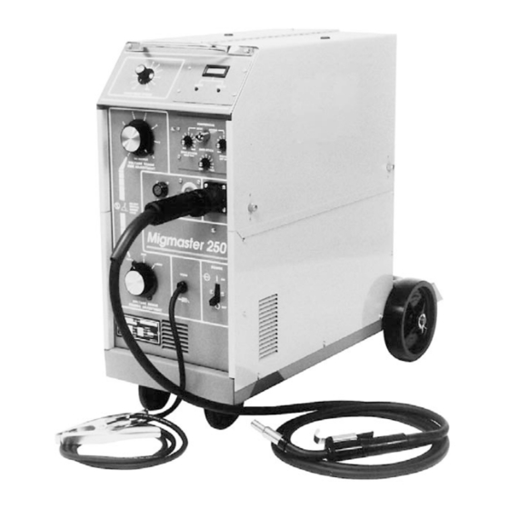
- Page 1 MigMaster 250 Welding Package Instruction Manual F15-087-J 04 / 2003...
- Page 2 Copies of this manual can be obtained by any of the following; Contacting your local ESAB supplier. Downloading a copy from the ESAB web site at www.esabna.com Sending a written request to ESAB WELDING &...
-
Page 3: Table Of Contents
TABLE OF CONTENTS SECTION NO. PAGE NO. SECTION 1 - SAFETY PRECAUTIONS FOR WELDING AND CUTTING ......................3 SECTION II - INTRODUCTION .................... 11 GENERAL ..........................11 RECEIVING-HANDLING ......................11 DESCRIPTION, Available Packages/Contents ............... 11 OPTIONAL ACCESSORIES ..................... 12 SAFETY ............................ 14 SECTION III - INSTALLATION .................... - Page 4 TABLE OF CONTENTS...
-
Page 5: Section No
SECTION 1 SAFETY PRECAUTIONS use. WARNING: hese Safety Precautions are for 5. Do not use equipment beyond its ratings. For example, your protection. They summarize precaution- overloaded welding cable can overheat and create a fire ary information from the references listed in hazard. -
Page 6: And Cutting
SECTION 1 SAFETY PRECAUTIONS EQUIPMENT MAINTENANCE -- Faulty or FUMES AND GASES -- Fumes and improperly maintained equipment can gases, can cause discomfort or harm, cause injury or death. Therefore: particularly in confined spaces. Do not breathe fumes and gases. Shield- 1. - Page 7 SECTION 1 PRECAUCION DE SEGURIDAD el calor causado por cable sobrecarga en los cables de soldar ADVERTENCIA: Estas Precauciones de Seguridad pueden ocasionar un fuego. son para su protección. Ellas hacen resumen de 6. Después de termirar la operación del equipo, inspeccione el área información proveniente de las referencias listadas de trabajo para cerciorarse de que las chispas o metal caliente en la sección "Información Adicional Sobre La Seguridad".
- Page 8 SECTION 1 PRECAUCION DE SEGURIDAD HUMO Y GASES -- El humo y los gases, MANTENIMIENTO DEL EQUIPO -- Equipo pueden causar malestar o daño, defectuoso o mal mantenido puede causar particularmente en espacios sin daño o muerte. Por lo tanto: ventilación.
- Page 9 SECTION 1 PRÉCAUTIONS DE SÉCURITÉ observer les précautions suivantes: AVERTISSEMENT: Ces règles de sécurité ont pour objet a. Éloigner suffisamment tous les matériaux combustibles d’ assurer votre protection. Veillez à lire et à observer les du secteur où l’on exécute des soudures ou des coupes précautions énoncées ci-dessous avant de monter l’...
- Page 10 52529 “Precautions and Safe Practices for Arc Weld- formation poches d’hydrogène, lesquelles ing, Cutting and Gouging” publié par ESAB. Nous conseillons également de consulter les publications présentent un danger d’explosion; ce ventilateur ne fonctionne que si l’interrupteur correspondant du sui-vantes, tenues à votre disposition par l’American Welding Society, 550 N.W.
-
Page 11: Section Ii - Introduction
6'-0" shielding gas supply hose w/fittings and running gear w/gas (cylinder) support, as follows: 2.2 RECEIVING-HANDLING -- Migmaster 250 for 208/230-Volt input ..P/N 32851 Prior to installing this equipment, clean all packing mate- -- Migmaster 250 for 208/230/380/400/460/575-Volt rial from around the unit and carefully inspect for any input ............ -
Page 12: Optional Accessories
This easy-to-install, plug-in module mounts in place of the lower blank cover plate of the upper-right front panel The Migmaster 250 System can be used to weld hard and location in the 250 unit. It enables the operator to use the aluminum wire with an optional ST-23A spool-gun torch. - Page 13 No. 6 XL Nozzle, (MT Std.) ....P/N 998895XL The Migmaster 250 unit is equipped with a built-in control No. 8 XL Nozzle, (MT Std.) ....P/N 998893XL for the ST-23A Spool-On-Gun welding torch. The ST- No.
-
Page 14: Safety
SECTION 2 INTRODUCTION 2.5 SAFETY Before the equipment is put into operation, the safety section at the front of this manual should be read com- pletely. This will help avoid possible injury due to misuse or improper welding applications. The symbol which precedes safety notes appear- ing throughout this manual means “Attention! Be Alert! Your safety is involved.”... -
Page 15: Section Iii - Installation
SECTION 3 INSTALLATION III. INSTALLATION 3.1 LOCATION (Figure 3.1) A proper installation site should be selected for the welding machine, if the unit is to provide dependable service and remain relatively maintenance free. A proper installation site permits freedom of air move- ment into and out of the welding machine, and also least subjects the unit to dust, dirt, moisture, and corrosive vapors. - Page 16 SECTION 3 INSTALLATION TABLE 3.1 Input Conductor and Fuse Size 3.2.2 Input Conductor Connections Recommended The input power cord on 208/230 Volts primary input Full Primary model is provided with an attachment plugcap. The Primary Load Input Ground plugcap will mate with a 250 Volts, 50 Ampere receptacle Input Line Fuse...
- Page 17 SECTION 3 INSTALLATION When changing the input voltage connections, the unused lead must be insulated and positioned to prevent contact with any other internal components of the machine or the machine side panel. The clear- ance between the unused lead and other compo- nents must be at least one inch (see Fig.
-
Page 18: Secondary Output Connections
Figure 3.3.1. cover around the power switch. Replace the side panel. 3.3 SECONDARY OUTPUT CONNECTIONS The Migmaster 250 Welding System is completely self- contained so that the front panel torch fittings (Euro-type MT and Spool gun) are internally connected to the welding polarity (D.C. -
Page 19: Connection Of The Shield Gas
R-33-FM-320, P/N 21558. 3.5.3 THREADING WELDING WIRE a. With the cylinder cap in place CAREFULLY slide the cylinder of gas onto the Migmaster 250 cylinder A. Turn off power switch. rack. b. Secure the cylinder to the unit, using the chain provided. -
Page 20: Welding Cable Connections
Migmaster 250 for leakage. Correct any leaks before starting work. 3.8 ASSEMBLE REAR WHEELS i. -
Page 21: Installing Optional Digital Meter
SECTION 3 INSTALLATION 3.10 INSTALLING OPTIONAL DIGITAL METER a. Remove the top blank-cover plate from the upper- right front panel of the power supply -- save the four mounting screws. b. Locate the harness-connected 10-pin plastic plug, PL1, inside the mounting cavity. This plug does not have a jumper plug connected to it. - Page 22 SECTION 3 INSTALLATION...
-
Page 23: Section Iv - Operation
SECTION 4 OPERATION 4.1.2 VOLTAGE CONTROL (Coarse Range Selector IV. OPERATION and Fine Adjustment Range Selector) 4.1 CONTROLS (See Figure 4.1) Voltage control is by means of two high current tap switches which connect the rectifier bridge to various 4.1.1 POWER SWITCH secondary taps. -
Page 24: Process Setup
D.C.R.P. (TORCH fitting is connected to Positive, and WORK cable/clamp is connected to The Migmaster 250 is equipped with a built-in control for Negative output). To weld using D.C.S.P., simply mount the Spool Gun which operates via the amphenol control... - Page 25 The required delay time generally depends on the WIRE SPEED Adjustment setting on the front panel F. Turn on the Migmaster 250’s power switch and - the higher the setting, the faster wire will feed into the begin seam mig welding.
-
Page 26: Section 4 Operation
SECTION 4 OPERATION B. Be sure a standard nozzle (and not a spot weld C. Set the “coarse” and “fine” Voltage control nozzle) is installed on the torch. switches and wire speed pot to the desired settings and begin welding operation as described in Sec- C. -
Page 27: Operating Procedures
SECTION 4 OPERATION 4.3 OPERATING PROCEDURES 4.3.1 OPERATING SAFETY PRECAUTIONS Comply with all ventilation, fire and other safety require- ments for arc welding as established in the SAFETY Section at the front of this manual. Also remember the following: A. Because of the radiant energy of the welding arc and the possibility of drawing an arc before the helmet is lowered over the face, the operator should wear flash goggles with filter lenses under... - Page 28 SECTION 4 OPERATION E. Never operate the equipment at currents greater b. Attempting to weld over grease or oil can cause weld defects. than the rated ampere capacity; overheating will occur. c. Before welding on aluminum, be sure to clean surface thoroughly using a stainless steel brush.
- Page 29 SECTION 4 OPERATION up or down, it is very important to keep the arc on the leading edge of the puddle to ensure complete pen- etration. Power supply contactor becomes energized the moment the torch trigger is depressed. Arcing can G.
- Page 30 SECTION 4 OPERATION TABLE 4.3, Continuous /Stitch Weld Conditions This equipment is provided with a thermostat (OL) in the transformer (T1) windings which will open and prevent the contactor (CON) from closing if the transformer windings are overheated. If the thermostat opens, allow the equip- ment to idle with fan running for approximately 15-min.
-
Page 31: Section V - Service
SECTION 5 SERVICE Regularly check cylinder valves, regulators, hoses, and V. SERVICE gas connections for leaks with soap solution. Check for and tighten loose hardware including electrical 5.1 MAINTENANCE connection. Loose power connections overheat during welding. Immediately replace all worn or damaged power cables Be sure the branch circuit or main disconnect switch and connectors. -
Page 32: Troubleshooting
SECTION 5 SERVICE The hermetically sealed silicon diode rectifiers are spe- abnormally high temperature, it will deenergize the cially designed for welding machine use and will not age contactor. This thermostat will reset itself automatically or deteriorate in use. The four diodes are mounted on after the transformer windings have cooled to a safe heat sinks. - Page 33 ESAB representative. 2. No welding power. a. Thermostat has opened. a. Wait 15 minutes with fan running. If still no power, contact ESAB repre- sentative. b. Shorted diode in main rectifier. b. Check diodes and replace if req’d. c. Open in wiring c.
- Page 34 SECTION 5 SERVICE WELD CONDITION POSSIBLE CAUSE REMEDY c. Loose connection. c. Check all welding cable connections. d. Malfunctioning capacitor bank. d. Check capacitors for low leakage resistance. 6. Stringy irregular bead, a. Torch moved too fast. a. Move Torch slower along seams. poor penetration.
- Page 35 SECTION 5 SERVICE WELD CONDITION POSSIBLE CAUSE REMEDY 13.Wire does not feed; motor a. Kink, etc. in wire, or wire bound a. Straighten; or feed wire until running (drive roll turns). on reel. clear and cut off. b. Wire freezing to contact tip b.
- Page 40 SECTION 5 SERVICE...
-
Page 41: Section Vi - Parts
(*) in the Stock No. column of the parts list be kept on hand. To assure proper operation, it is recommended that only genuine ESAB parts and products be used with this 6.2 REPLACEMENT PARTS equipment. To order replacement parts: The following illustrations of the equipment identify each a. - Page 42 SECTION 6 REPLACEMENT PARTS 11, 12 21, 22, 23 13,14 18, 19 16, 17 FIGURE 6.1 MIGMASTER 250 SYSTEMS ITEM PART CKT. REQ. DESCRIPTION (Figure 6.1) DESIG. 33188YL PANEL, SIDE, RIGHT 950769• STRAIN, RELIEF 1373 0623 LATCH, DOOR 33192M PLATE, BLANK COVER*...
- Page 43 SECTION 6 REPLACEMENT PARTS 19,20 15,16 FAN ASSEMBLY See Figure 6.4 5,25 22,23 FIGURE 6.2 MiGMASTER 250 Main Assembly (Left Side)
- Page 44 SECTION 6 REPLACEMENT PARTS ITEM QTY. PART CKT. REQ. DESCRIPTION (Figure 6.2) DESIG. 33184M BASE 672225 INSULATOR STANDOFF 1373 6750 TRANSFORMER, MAIN - for 208/230 v. model 33176 TRANSFORMER, MAIN - for 208-575 v. model 951634 VALVE, SOLENOID, 24 V(from 1/1/94) SOL1 1373 0628 VALVE, SOLENOID (before 1/94)
- Page 45 SECTION 6 REPLACEMENT PARTS 9,10 FIGURE 6.3 MiGMASTER 250 Main Assembly (Right Side)
- Page 46 SECTION 6 REPLACEMENT PARTS ITEM PART CKT. REQ. DESCRIPTION (Figure 6.3) DESIG. 33186M REAR, PANEL 2360 5057GY SUPPORT, REEL 2360 6237 HUB, REEL (See Figure 6.5) 634519 SWITCH, TOGGLE, 4 PDT 1373 5464 FUSE, 10A 634709 HOLDER, FUSE 2361 2348 GEAR MOTOR, 50-675 IPM 2361 2479 KEY, MOTOR SHAFT...
- Page 47 SECTION 6 REPLACEMENT PARTS 4, 3 10, 9 FIGURE 6.4 MIGMASTER 250 FAN & CAPACITOR BANK ITEM QTY. PART CKT. REQ. DESCRIPTION (Detail "B" FAN) DESIG. 99511916 DIODE, SILICON, STRAIGHT POLARITY D1, D2 1373 0680 INSULATOR, COLLAR 1373 0681 INSULATOR, SHOULDER...
- Page 48 SECTION 6 REPLACEMENT PARTS 6, 7 2, 3 FIGURE 6.5b MIGMASTER 250 LEXAN HUB KIT ITEM QTY. PART CKT. REQ. DESCRIPTION (HUB KIT) DESIG. 0558002993 D-Shaft, Wirefeeder, 5.75L 61341133 Screw, HC, .375-16 x 1.00 64302037 Washer, Lock, .375 0558002992 Bracket, Spool Support...
- Page 49 SECTION 6 REPLACEMENT PARTS 1 (Includes, 2,3,4,7,8) *7,8 *2,4 *10,6 Items shown in exploded view for clarity. 2-Roll (Undriven Upper) Drive Stand ITEM QTY. PART REQ. DESCRIPTION 952939 2 ROLL WIRE DRIVE SYSTEM, CONSISTS OF: 952704 PRESSURE ARM ASSY., (incls. 2, 3, 4, 7, 8) 23612477 AXLE, PRESSURE 23612475...
- Page 50 SECTION 6 REPLACEMENT PARTS *103 *104 *108 *110 *109 *112 Items shown in exploded view for clarity. 2-Roll (Undriven Upper) Drive Stand Assembly, 952583 - Migmaster 251 Qty. Item Circuit Req. Description Symbol 23612470 Pivot Pin 23612460 Pressure Device Complete 952592 Pressure Arm Complete 952593...
- Page 51 SECTION 6 REPLACEMENT PARTS *6,10 13,16 *13,16 Items shown in exploded view for clarity. 2-Roll (Driven Upper) Drive Stand ITEM QTY. PART REQ. DESCRIPTION 23612627 2 ROLL GEARED WIRE DRIVE SYSTEM, CONSISTS OF: 23612626 PRESSURE ARM ASSY., (incls. 2, 3, 4, 7, 8) 23612387 AXLE, PRESSURE 23612475...
- Page 52 SECTION 6 REPLACEMENT PARTS...
- Page 53 NOTES...
- Page 54 NOTES...
-
Page 55: Revision History
Revision History The "G" edition (6/99) of this manual covers the following: Added contact tips modified for improved arc performance on steel and cored wires in Table 2.4.5.1. Added end drive roll/pressure roll combinations for use with soft cored wires in Table 2.4.5.2. - Page 56 ESAB Welding & Cutting Products, Florence, SC Welding Equipment COMMUNICATION GUIDE - CUSTOMER SERVICES A. CUSTOMER SERVICE QUESTIONS: Telephone: (800)362-7080 / Fax: (800) 634-7548 Hours: 8:00 AM to 7:00 PM EST Order Entry Product Availability Pricing Order Information Returns B. ENGINEERING SERVICE:...
Need help?
Do you have a question about the MigMaster 250 and is the answer not in the manual?
Questions and answers