ESAB Multimaster 260 Instruction Manual
Jessejames signature series mig/tig/stick welding package
Hide thumbs
Also See for Multimaster 260:
- Instruction manual (62 pages) ,
- Installation instructions (2 pages)

Related Manuals for ESAB Multimaster 260


Summary of Contents for ESAB Multimaster 260
- Page 1 Multimaster 260 MIG/TIG/STICK WELDING PACKAGE Instruction Manual 0558005188 08/2007...
-
Page 2: User Responsibility
Be sure this information reaches the operator. You can get extra copies through Your supplier. caution these instructions are for experienced operators. if you are not fully familiar with the principles of operation and safe practices for arc welding and cutting equipment, we urge you to read our booklet, “precautions and safe practices for arc Welding, cutting, and gouging,”... -
Page 3: Table Of Contents
taBle of contents section / title page Safety Precautions ..................5 Safety - English . - Page 4 taBle of contents...
-
Page 5: Safety Precautions
section 1 safetY precautions safety precautions safety - english Warning: These Safety Precautions are fires anD explosions -- heat from for your protection. They summarize pre- flames and arcs can start fires. hot cautionary information from the references slag or sparks can also cause fires and listed in Additional Safety Information sec- explosions. - Page 6 section 1 safetY precautions 1. Be sure the power source frame (chassis) is con- 3. Welders should use the following procedures to nected to the ground system of the input power. minimize exposure to EMF: 2. Connect the workpiece to a good electrical A.
- Page 7 section 1 safetY precautions 5. Warning: this product, when used for welding 1. Always have qualified personnel perform the instal- or cutting, produces fumes or gases lation, troubleshooting, and maintenance work. which contain chemicals known to Do not perform any electrical work unless you are the state of california to cause birth qualified to perform such work.
- Page 8 section 1 safetY precautions 5. AWS C5.5 - "Recommended Practices for Gas Tung- sten Arc Welding“ 6. AWS C5.6 - "Recommended Practices for Gas Metal Arc Welding"“ 7. AWS SP - "Safe Practices" - Reprint, Welding Hand- book. 8. ANSI/AWS F4.1, "Recommended Safe Practices for Welding and Cutting of Containers That Have Held Hazardous Substances."...
-
Page 9: Safety - Spanish
section 1 seguriDaD safety - spanish La escoria puede estar caliente y desprenderse con velocidad. Personas cercanas deberán usar gafas aDVertencia: Estas Precauciones de Se- de seguridad y careta protectora. guridad son para su protección. Ellas hacen resumen de información proveniente de las fuego Y explosiones -- el calor de referencias listadas en la sección "Información Adi- las flamas y el arco pueden ocacionar... - Page 10 section 1 seguriDaD 1. Asegúrese de que el chasis de la fuente de poder 3. Los soldadores deberán usar los siguientes proced- esté conectado a tierra através del sistema de imientos para minimizar exponerse al EMF: electricidad primario. 2. Conecte la pieza de trabajo a un buen sistema de A.
- Page 11 section 1 seguriDaD 5. aDVertencia-- este producto cuando se uti- 1. Siempre tenga personal cualificado para efec- liza para soldaduras o cortes, tuar l a instalación, diagnóstico, y mantenimiento produce humos o gases, los del equipo. No ejecute ningún trabajo eléctrico a cuales contienen químicos menos que usted esté...
- Page 12 section 1 seguriDaD significaDo De los simBolos -- según usted avanza en la lectura de este folleto: los símbolos sig- nifican ¡atención! ¡esté alerta! se trata de su seguridad. significa riesgo inmediato que, de no ser evadido, puede resultar inmediatamente en serio daño personal o la muerte.
-
Page 13: Safety - French
section 1 sÉcuritÉ safety - french incenDies et explosions -- la chaleur provenant des flammes ou de aVertissement : Ces règles de sécurité l'arc peut provoquer un incendie. le ont pour but d'assurer votre protection. Ils laitier incandescent ou les étincelles récapitulent les informations de précaution provenant des références dans la section peuvent également provoquer un... - Page 14 section 1 sÉcuritÉ 1. Assurez-vous que le châssis de la source 3. Les soudeurs doivent suivre les procédures suivantes d'alimentation est branché au système de mise à pour minimiser l'exposition aux champs électriques la terre de l'alimentation d'entrée. et magnétiques : 2.
- Page 15 section 1 sÉcuritÉ 5. aVertissement : ce produit, lorsqu'il est utilisé entretien De l'ÉQuipement -- un équipe- dans une opération de soudage ou de ment entretenu de façon défectueuse ou coupage, dégage des vapeurs ou des inadéquate peut causer des blessures gaz contenant des chimiques consid- graves ou mortelles.
- Page 16 section 1 sÉcuritÉ signification Des sYmBoles ce symbole, utilisé partout dans ce manuel, signifie "attention" ! soyez vigilant ! Votre sécurité est en jeu. Danger signifie un danger immédiat. la situation peut entraîner des blessures graves ou mortelles. aVertissement signifie un danger potentiel qui peut entraîner des blessures graves ou mortelles.
-
Page 17: Description
Ordering Information The Multimaster 260 is a DC welding system designed for Mig (GMAW), Tig (GTAW) or Stick (SMAW) welding. In the Mig mode this unit is capable of operating with short arc or spray arc transfer and handles both solid wires and tubular cored wires. -
Page 18: Optional Equipment
section 2 Description Digital Meter Voltage Preset Volts, Amps, and Wire feed speed Status Indicators Process Selector Voltage/Current Control Wire Feed Speed Control Remote Control Option “Spool-on-Gun” Option Optional Equipment Pre/Post Flow/Spot/Burnback module ........0558002889 Inductance Control Module ............0558002888 Remote Control Module .............. -
Page 19: General
section 2 Description 2.1 general This manual has been prepared for experienced welders. Do NOT permit untrained persons to install, operate or maintain this equipment. Do NOT attempt to install or operate this equipment until you have read and fully understand these instructions. -
Page 20: Controls
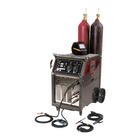
2.6 controls The Multimaster 260 can be used to weld solid and flux cored wires. The operator selects the process desired on a three position switch located on the front panel. A detailed description of the power source controls is included in Section 4 (Operation) of this manual. - Page 21 section 2 Description Choice of Argon or CO Regulator/ Flowmeter 6’ Gas Hose Eyetech Automatic Helmet (Optional) Simple To Use Weld Controls Cylinder Safety Chain Large, Easy To Read Digital Displays for Wire Welding Gloves Speed, Amps and Volts (not shown, optional) Simple and quick polarity change-over...
- Page 22 section 2 Description Inductance Burnback Preflow/postflow Hinged Wire Spot (Options) Compartment Door Handle 4 Roll Drive Stand 2 Cylinder Low Mount Tray Wheel Kit Adaptable Installed Spindle Assembly Tool Box with Small Parts Tray Voltage Switch Compartment figure 1B - components...
-
Page 23: Installation
section 3 installation 3.0 installation 3.1 location Several factors should be considered when selecting an installation site. Adequate ventilation is necessary to provide cool- ing, and the amount of dirt and dust to which the machine is exposed should be minimized. There should be at least 18 inches of unrestricted space between the machine’s side and rear panels and the nearest obstruction to provide freedom of air movement through the power source. -
Page 24: Handle Assembly Installation
3.2 hanDle assemBlY installation The Multimaster 260 is factory assembled except for the front handle assembly which is mounted to the machine upside down for shipping purposes. The handle assembly consists of two brackets and a cross bar. To install the handle in its proper position, do the following: A. -
Page 25: Electrical Input Connections
section 3 installation 3.3 electrical input connections In order to provide a safe and convenient means to completely remove all electrical power from the machine, it is highly recommended that a line disconnect switch be installed in the input circuit of the machine. Before making electrical input connections to the welding machine, “machinery lockout procedures”... -
Page 26: Voltage Changeover
The voltage changeover terminal board is located in the tool compartment on the left side of the machine. As shipped from the factory, the Multimaster 260 is configured for the highest connectable voltage. If using the other input voltages, the links on the terminal board (TB) inside the unit must be repositioned for the appropriate input voltage. - Page 27 section 3 installation figure 4a - figure 4D - input terminal Board input terminal Board 230/460/575 Vac model 208/230 Vac model 230 Vac Configuration 208 Vac Configuration figure 4e - figure 4B - input terminal Board 208/230 Vac model input terminal Board 230/460/575 Vac model 230 Vac Configuration 460 Vac Configuration...
-
Page 28: Secondary Output Connections
3.5 seconDarY output connec tions (figure 5) The Multimaster 260 Welding System is completely self-contained so that the front panel gun/torch connections are in- ternally connected to the welding polarity (DCEP or DCEN) via the secondary output terminals depending on the welding process being used. -
Page 29: Wire Feeder Mechanism
section 3 installation 3.7 Wire feeDer mechanism 3.7.1 DriVe rolls (figure 7 and 9) The drive roll has two grooves: the small groove feeds .035 in. diameter wire, the large groove feeds .045 in. wire. The groove nearest the gear motor feeds the wire. If the required groove is not correctly positioned, perform the following: A. -
Page 30: Threading Welding Wire
section 3 installation 3.7.2 WelDing Wire spool installation as with any work area, make sure safety glasses with side shields are worn when caution handling or changing wire or clipping wire off at the spool or at the end of the torch. -
Page 31: Section 3 Installation
section 3 installation 3.7.4 spool BraKe Drag aDJustment Spool brake disc friction should provide enough drag to keep the wire spool from spinning freely after wire feed stops. If adjustment is required, turn the adjusting screw inside the spindle housing clockwise to increase drag or counterclockwise to decrease it. -
Page 32: Connection Of Shielding Gas Supply
10-50 cfh table 2 - typical flow rates A. With the cylinder cap in place, CAREFULLY slide the cylinder of gas onto the Multimaster 260 cylinder rack. Secure the cylinder to the unit using the chain provid ed. C. Unscrew the cylinder cap. - Page 33 Close the flow control valve on the flowmeter. G. Attach the gas hose from the rear of the Multimaster 260 to the regulator outlet connection. H. Open the cylinder valve SLOWLY a fraction of a turn. This will prevent damage to the gauge and critical components in the regulator.
- Page 34 section 3 installation...
-
Page 35: Operation
4.1.3 temp lamp (figure 12) The TEMP lamp illuminates if an over temperature condition occurs within the Multimaster 260. This condition may be caused by excessive duty cycle or over-current conditions. When an over temperature condition occurs, the welding output is turned off and the unit must be allowed to cool. -
Page 36: Section 4 Operation
section 4 operation 4.1.8 tig and sticK WelDing In the TIG and STICK process mode, you must depress and hold the PRESET button while presetting the welding current in the top display. Releasing the preset button causes the display to return to zero. Once welding begins, the display will show average welding current and volts in the top and bottom display, respectively. - Page 37 section 4 operation WFS - IPM Preset Weld Process Lamp Button Amps Switch Digital Meters Lamp Voltage Set - MIG Amps/Volts/WFS Current Set - STICK/TIG Power “ON” Lamp Temperature Lamp Fault Lamp Wire Feed Speed Trim figure 12 - control panel Main Power Switch Mig Gun...
-
Page 38: Optional Controls
section 4 operation 4.2 optional controls 4.2.1 inDuctance trim (optional) p/n-0558002888 (figure 14) Inductance is used to optimize short circuiting arc performance by changing the current rise and fall time of each short circuit. This results in improved spatter control, weld bead wetting and arc stability. It is HIGHLY RECOMMENDED that the Inductance Trim option be used for optimum short arc welding performance with stainless steel wires. - Page 39 section 4 operation 4.2.2 prefloW/postfloW/spot/BurnBacK (optional) p/n-0558002889 (figure 15) This optional control is mounted in place of the standard burnback control inside the wire spool compartment. A description of the module follows: A. Preflow/Postflow - The PREFLOW control sets the time of the preflow shielding gas before the wire starts feeding (0-1.5 sec.).
- Page 40 This module mounts to the front panel just left of the Mig Gun trigger connectors and allows the use of either the MT-250- SG or ST-23A spool guns with the Multimaster 260. The module has a switch to select either spool gun or regular Mig gun operation.
-
Page 41: Mig Welding Set-Up
WelDing set-up When the PROCESS switch is placed in the MIG position the Multimaster 260 is set to turn ”ON” when the Mig Gun trigger is depressed. Step 1. Choose the weld parameters based of the wire alloy, diameter, material thickness and shielding gas from Table 3 - MIG PARAMETERS CHART. -
Page 42: Tig Welding Setup
2 volts to the data table value. tig WelDing setup When the PROCESS switch is placed in the TIG position, the Multimaster 260 turns “ON” the weld contactor so that power is immediately available to the output connection. The Touch TIG starting system is then enabled. - Page 43 section 4 operation NOTE: The Wirespeed 3 knob has no effect in the TIG mode. figure 21- tig front control panel figure 20 - tig polarity connection table 4 - tig parameters chart...
-
Page 44: Handling The Tig Torch
section 4 operation Warning comply with all ventilation, fire and other safety requirements for arc welding as established in the safetY section at the front of this manual. 4.5 hanDling the tig torch starting the arc There is nothing difficult or technical about starting an arc in the proper manner. We recommend the particular procedure outlined briefly below, to ensure maximum protection of the workpiece from the atmosphere at the start of welding opera- tions. -
Page 45: Stick Welding Set-Up
WelDing set-up When the PROCESS switch is placed in the STICK position, the Multimaster 260 turns “ON” the weld contactor so that power is immediately available to the output connection. This means that the STICK electrode holder is “HOT”, and an arc will strike when the electrode comes in contact with the workpiece or any other object at ground potential. - Page 46 section 4 operation...
-
Page 47: Maintenance
section 5 maintenance 5.0 maintenance 5.1 maintenance anD serVice Be sure that the Branch circuit or main Disconnect sWitch anD multimas- ter poWer sWitch are off or electrical input fuses are remoVeD Before Warning attempt ing anY inspection or WorK insiDe the poWer source. placing the poWer sWitch on the poWer source in the off position Does not remoVe all poWer from insiDe the eQuipment. -
Page 48: Fan Motor
section 5 maintenance 5.2.1 poWer source 5.2.1.1 rectifiers anD transistors It is recommended that the internal components be cleaned occasionally by blowing them out with low pressure compressed air. This cleaning operation is necessary so that maximum cooling will be accomplished by the air stream. This should be done periodically, depending upon the location of the unit and the amount of dust and dirt in the atmosphere. -
Page 49: Replacement Parts
To ensure proper operation, it is recommended that only genuine ESAB parts and products be used with this equipment. The use of non-ESAB parts may void your warranty. Replacement parts may be ordered from your ESAB Distributor. - Page 50 section 6 replacement parts 20, 21 figure 24 - right side front View torch aDaptor assemBlY (internal View) 26,27 torch aDaptor assemBlY (external View)
- Page 51 section 6 replacement parts figure 24 - right side front View (con’t) QtY. item circuit reQ. Description sYmBol 952895 SWITCH PB NORMALLY OPEN 672831 SWITCH TOGGLE SPDT 951474 SWITCH SEAL BLACK 0558005430 BRACKET RH HANDLE 13730632 POT LIN 10.0K 2.00W .88L R1,R2 0558001019 KNOB 1.57 DIA.
- Page 52 6 replacement parts figure 25 - left side front View of multimaster 260 QtY. item circuit reQ. Description sYmBol 0558001692M DOOR TOP LEFT (HINGE & HINGE BRACKET NOT INCLUDED) 0558002593M COVER TOP FRONT 38196 PCB ASSY. DISPLAY PCB2 38182...
- Page 53 section 6 replacement parts 64,65 67, 68 Figure 26 - inside left View of multlimaster 260 QtY. item circUit reQ. Description sYmBol 0558001710M FAN MOUNT 0558002490 MOTOR 950592 FAN BLADE 0558001577 MAIN TRANSFORMER 208/230V 0558001580 MAIN TRANSFORMER - 230/460/575V 99511915 DIODE REV 200V 250A D1,2 99511916...
-
Page 54: Section 6 Replacement Parts
section 6 replacement parts (Not Shown) - Page 55 6 replacement parts figure 27 - inside right & rear View of multimaster 260 (cont.) QtY. item circuit reQ. Description sYmBol 948258 SPINDLE MOLDED (SEE FIGURE 28) 0558002543M REAR COVER 0558003076 TRANSISTOR REPLACEMENT KIT IGBT MATCHED PAIR 600V - 300A...
- Page 56 section 6 replacement parts for units with serial numbers xxxJ230001 (mid July 2002 forward) DRIVE ROLLS (See Drive Roll & Guide Tube Selection Guide on Following Pages) NOTE: Measure hole placement to distingush between early & cur- rent verison drive stands figure 28 - auto-lift mini four roll geared Wire Drive system - 0558001339 for units with serial numbers starting xxxJ230001 (mid July 2002 forward) QtY.
- Page 57 section 6 replacement parts Drive roll and guide tube selection Wire type guide tube roll Drive* & Diameter hard Wires (“V” groove) .023 in. (0.6 mm) 21155 0558001077 .030 in. (0.8 mm) 21155 0558001077 .035 in. (0.9 mm) 21156 0558001078 .045 in.
- Page 58 section 6 replacement parts figure 30 - spindle assembly for migmaster 260 QtY. item circuit reQ. Description sYmBol 0558002561M WIRE SPOOL MOUNT BRACKET 948258 MOLDED SPINDLE 634347 CLIP HITCH .16D X 3.25L 948255 BRAKE PADS 36756 “D” SHAFT ALUMINUM...
- Page 59 notes...
- Page 60 notes...
-
Page 61: Revision History
reVision historY Original release - 04/2005 Revision - 05/2006 - Updated Handle Assembly Installation subsection per inputs from Ray Lundy. Revision - 08/2007 - Changed Specifications in Sect 2 - Process: MIG (GMAW), Open Circuit Voltage (max): from: 70 Vdc to: 39.0 Vdc per D. Perkins. - Page 62 Welding & cutting products, florence, sc Welding equipment communication guiDe - customer serVices CUSTOMER SERVICE QUESTIONS: Telephone: (800)362-7080 / Fax: (800) 634-7548 Hours: 8:00 AM to 7:00 PM EST Order Entry Product Availability Pricing Order Information Returns ENGINEERING SERVICE:...
Need help?
Do you have a question about the Multimaster 260 and is the answer not in the manual?
Questions and answers