Table of Contents
Advertisement
INSTRUCTIONS for
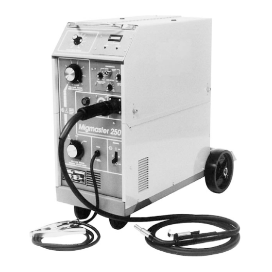
MIGMASTER 250
NOTE:
These INSTRUCTIONS are for experienced operators. If you are not fully familiar with the principles
of operation and safe practices for electric welding equipment, we urge you to read our booklet,
"Precautions and Safe Practices for Arc Welding, Cutting and Gouging." Form 52-529. Do NOT permit
untrained persons to install, operate, or maintain this equipment. Do NOT attempt to install or operate
this equipment until you have read and fully understand these Instructions. If you do not fully
understand these Instructions, contact your supplier for further information. Be sure to read the
Safety Precautions on page 2 before installing or operating this equipment.
Be sure this information reaches the operator.
You can get extra copies through your supplier.
WELDING PACKAGES
This manual is also suitable for use with L-TEC Migmaster 250 package.
F-15-087-E
August, 1997
Advertisement
Table of Contents

Related Manuals for ESAB MIGMASTER 250


Summary of Contents for ESAB MIGMASTER 250
- Page 1 WELDING PACKAGES NOTE: This manual is also suitable for use with L-TEC Migmaster 250 package. These INSTRUCTIONS are for experienced operators. If you are not fully familiar with the principles of operation and safe practices for electric welding equipment, we urge you to read our booklet, "Precautions and Safe Practices for Arc Welding, Cutting and Gouging."...
-
Page 2: User Responsibility
USER RESPONSIBILITY This equipment will perform in conformity with the description thereof contained in this manual and accompanying labels and/or inserts when installed, operated, maintained and repaired in accordance with the instructions provided. This equipment must be checked periodically. Defective equipment should not be used. Parts that are broken, missing, worn, distorted or contaminated should be replaced immediately. -
Page 3: Table Of Contents
TABLE OF CONTENTS SECTION NO. PAGE NO. SECTION 1 - GENERAL SAFETY RULES FOR WELDING AND CUTTING ......................4 GENERAL PRECAUTIONS ....................4 PRECAUTION SYMBOL DEFINITIONS ................ 5 SECTION II - INTRODUCTION ..................... 6 GENERAL ........................6 RECEIVING-HANDLING .................... 6 DESCRIPTION, Available Packages/Contents ............ -
Page 4: General Precautions
SAFETY PRECAUTIONS WARNING: hese Safety Precautions are for 5. Do not use equipment beyond its ratings. For example, your protection. They summarize precautionary overloaded welding cable can overheat and create a fire information from the references listed in Addi- hazard. tional Safety Information section. -
Page 5: And Cutting
FUMES AND GASES -- Fumes and 2. Before performing any maintenance work inside a power gases, can cause discomfort or harm, source, disconnect the power source from the incoming particularly in confined spaces. Do electrical power. not breathe fumes and gases. Shield- 3. -
Page 6: Section Ii - Introduction
(cylinder) support, as follows: ment. All information presented here in should be given careful consideration to assure optimum performance of -- Migmaster 250 for 208/230-Volt input ..P/N 32851 this equipment. -- Migmaster 250 for 208/230/380/400/460/575-Volt input ............P/N 32852 2.2 RECEIVING-HANDLING... -
Page 7: Optional Accessories
2.4.1 SPOT/STITCH/ANTI-STICK MODULE, P/N 2.3.5 CONTROLS 32858. The Migmaster 250 System can be used to weld hard and This easy-to-install, plug-in module mounts in place of aluminum wire with an optional ST-23A spool-gun torch. the lower blank cover plate of the upper-right front panel An optional spot/stitch control allows a welder to spot or location in the 250 unit. - Page 8 (see F-14-353). No. 8 Nozzle (1/2" I.D.) ......P/N 999471 The Migmaster 250 unit is equipped with a built-in control No. 10 Nozzle (5/8" I.D.) ......P/N 999472 for the ST-23A Spool-On-Gun welding torch. The ST- No. 12 Nozzle (3/4" I.D.) ......P/N 999473 23A is a high performance, 250 ampere continuous duty No.
-
Page 9: Safety
2.5 SAFETY Before the equipment is put into operation, the safety section at the front of this manual should be read ‡ completely. This will help avoid possible injury due to misuse or improper welding applications. The symbol which precedes safety notes appear- ing throughout this manual means “Attention! Be Alert! Your safety is involved.”... - Page 10 A. Input Electrical Requirements TABLE 3.1 Input Conductor and Fuse Size Recommended Full Primary Primary Load Input Ground Input Line Fuse Conductor Conductor Volts Amperes Size Size Size B. Input Conductor Connections Only qualified personnel should make these changes. Make certain the primary power has been discoonnected and all safety procedures have been followed before proceeding with these instructions.
- Page 11 When changing the input voltage connections, the unused lead must be insulated and positioned to prevent contact with any other internal components of the machine or the machine side panel. The clear- ance between the unused lead and other compo- nents must be at least one inch (see Fig.
-
Page 12: Secondary Output Connections
3.3 SECONDARY OUTPUT CONNECTIONS insulating cover around the power switch. Replace the side panel. The Migmaster 250 Welding System is completely self- contained so that the front panel torch fittings (Euro-type MT and Spool gun) are internally connected to the welding polarity (D.C. -
Page 13: Connection Of The Shield Gas
580. 3.5.3 THREADING WELDING WIRE a. With the cylinder cap in place CAREFULLY slide A. Turn off power switch. the cylinder of gas onto the Migmaster 250 cylinder rack. b. Secure the cylinder to the unit, using the chain provided. -
Page 14: Welding Cable Connections
Migmaster 250 for leakage. Correct any leaks before starting work. 3.8 ASSEMBLE REAR WHEELS i. If work is to be stopped for a half-hour or more, or... -
Page 15: Section Iv - Operation
4.1.2 VOLTAGE CONTROL (Coarse Range Selector and Fine Adjustment Range Selector) IV. OPERATION 4.1 CONTROLS (See Figure 4.1) 4.1.1 POWER SWITCH COARSE VOLTAGE RANGE Selector 4.2.3 4.2.2 Secondary Output Terminals 4.1.5 2.4.2 for Welding Polarity Change- over, see 4.1.3. 4.1.6 10A. -
Page 16: Process Setup
FINE VOLTAGE ADJUSTMENT Selector 4.1.5 WIRE FEED SPEED CONTROL 4.1.6 STD./SPOOL GUN SELECTOR CAUTION: These tap switches carry several hundred amperes, and must not be switched under load, as this will cause the contacts of the switches to arc. 4.1.3 SECONDARY WELDING CONNECTIONS 4.2 PROCESS SETUP 4.2.1 STANDARD MIG SEAM WELDING W/MT-200CC 4.2.2 ST-23A SPOOL-ON-GUN CONTROL CONNEC-... - Page 17 Figure 4.2.2 - Connecting Spool-On-Gun to Services 4.2.3 OPTIONAL SPOT/STITCH/ANTI-STICK CON- TROL MODULE 4.2.3.2 CONTINUOUS WELDING MODE OPERATION 4.2.3.1 ANTI-STICK WELDING OPERATION...
- Page 18 4.2.3.3 SPOT WELDING MODE OPERATION Fig. 4.2.3 - Cross Section of Good Spotweld Power supply contactor becomes energized the mo- ment the torch trigger is depressed. Arcing can occur if the wire is brought to a ground. Keep the torch always from ground until welding is to begin. 4.2.5 DUTY CYCLE (Figure 4.2.5) 4.2.4 STITCH WELDING MODE OPERATION...
-
Page 19: Operating Procedures
4.3 OPERATING PROCEDURES 4.3.1 OPERATING SAFETY PRECAUTIONS Fig. 4.2.5 Duty Cycle Curves 4.2.6 VOLT/AMPERE CURVES (Figure 4.2.6) Figure 4.2.6 VOLT/AMPERE CURVES... - Page 20 4.3.3 SET-UP PROCEDURE Never operate the welding machine with any por- tion of the outer enclosure removed. In addition to a hazard, improper cooling may result in damage to the welding transformer and the welding machine components. Warranty is void if the machine is operated with any portion of the outer enclosure removed.
- Page 21 Power supply contactor becomes energized the mo- ment the torch trigger is depressed. Arcing can occur if the wire is brought to a ground. Keep the torch away from ground until welding is to begin How- ever, the Coarse Voltage Range and Fine Voltage setting must not be switched while welding.
-
Page 22: Section V - Service
MIG PROCESS SELECTION GUIDE MIG PROCESS SELECTION GUIDE SETTING TO SET MACHINE SHOWN AS: Find the thickness of the base plate to be welded. Find the diameter of the filler wire to be used. Voltage Find the suggested arc voltage, range and wire feed setting by following Voltage Range the wire diameter row across (to the right) and the plate thicknesses Wire Feed... -
Page 23: Troubleshooting
5.2.1 POWER SOURCE 5.2.1.1 RECTIFIER If it should become necessary to replace this or any other fuse in the welding machine, ensure that the proper size fuse is used as a replacement. 5.2.1.5 OVER-TEMPERATURE PROTECTION 5.2.2 WIRE FEEDER NOTE: Thermal conductive compound (Wakefield En- gineering #120 Thermal Compound or equiva- lent) must be reapplied to heat sink-diode mat- 5.3 TROUBLESHOOTING... - Page 24 5.3.1 IF MOTOR DOES NOT RUN: General Replacement 5.3.3 SOLENOID VALVE REPLACEMENT Many troubleshooting situations require that the power remain On and that power terminals in the equipment carry voltage. Exercise extreme caution when working on “LIVE” equipment. Avoid contact with electrical components, except when testing 5.3.2 DRIVE ROLL PRESSURE ADJUSTMENT with an appropriate instrument.
- Page 25 WELD CONDITION POSSIBLE CAUSE REMEDY...
-
Page 26: Section Vi - Parts
WELD CONDITION POSSIBLE CAUSE REMEDY VI. PARTS 6.1 SPARE PARTS 6.3 ORDERING 6.2 REPLACEMENT PARTS... - Page 31 FAN/CAPACITOR BANK ASSEMBLY See Figure 6.4 FIGURE 6.1 MIGMASTER 250 MAIN ASSEMBLY (Left Side) ITEM QTY. PART CKT. REQ. DESCRIPTION (Figure 6.1) DESIG. (see Note below) NOTE: If contactor, 13734781, life is short due to high current, repetitive welding, replace with 60 amp...
- Page 32 11, 12 21, 22 23, 24 18, 19 16, 17 FIGURE 6.2 MIGMASTER 250 SYSTEMS ITEM PART CKT. REQ. DESCRIPTION (Figure 6.2) DESIG. * Photo shows optional Digital Volt/Ammeter Module, P/N 32857, and Spot/Stitch/Anti-Stick Control Module, P/N 32858. • Was 97W63, changed to 950769, 6/95.
- Page 33 9, 10 FIGURE 6.3 MIGMASTER 250 MAIN ASSEMBLY (Right Side) ITEM QTY PART CKT. REQ. DESCRIPTION (Figure 6.3) DESIG. + - DENOTES RECOMMENDED ON HAND SPARE PART - Added "D" Edition, 3/96...
- Page 34 4, 3 10, 9 FIGURE 6.4 MIGMASTER 250 FAN & CAPACITOR BANK ITEM QTY. PART CKT. REQ. DESCRIPTION (Detail "B" FAN) DESIG. 7 6 5 REF. FIGURE 6.5 MIGMASTER 250 LEXAN HUB KIT ITEM QTY. PART CKT. REQ. DESCRIPTION (HUB KIT)
- Page 35 Figure 6-6. 2-Roll Drive Stand Item Part Req. Description 23612627 2 ROLL GEARED WIRE DRIVE SYSTEM, CONSISTS OF: 23612626 PRESSURE ARM ASSY ., (incls. 2, 3, 4, 7, 8) 23612387 AXLE, PRESSURE ROLL 23612475 PRESSURE ARM 23612385 CIRCLIP, PRESSURE ROLL 23612470 PIVOT PIN 23612472...
- Page 36 ESAB Welding & Cutting Products, Florence, SC Welding Equipment COMMUNICATIONS GUIDE - CUSTOMER SERVICES A. CUSTOMER SERVICE QUESTIONS: Telephone (803) 664-5540/Fax: (800) 634-7548 Order Entry Product Availability Pricing Hours: 8:30 AM to 5:00 PM EST Order Changes Saleable Goods Returns...
Need help?
Do you have a question about the MIGMASTER 250 and is the answer not in the manual?
Questions and answers
Wire speed too fast and can not adjust
To adjust the wire speed on the ESAB MIGMASTER 250 if it is too fast, turn the wire speed potentiometer knob on the front panel to a lower number. The lower the number, the slower the wire feed speed.
This answer is automatically generated