Advertisement
Advertisement
Table of Contents

Related Manuals for ESAB PLASMAWELD 202


Summary of Contents for ESAB PLASMAWELD 202
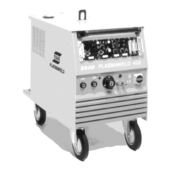
- Page 1 Plasmaweld 202, Plasmaweld 402 Instruction manual 0457 974 074...
-
Page 2: Table Of Contents
INDEX Page Safety advice Technical data PLW 202 Technical data PLW 402 Technical description Installation Welding Data sheet plasma welding Accessories Maintenance Trouble shooting Spare parts... -
Page 3: Protect Yourself And Others
!WARNING! ARC WELDING AND CUTTING CAN BE INJURIOUS TO YOURSELF AND OTHERS. TAKE PRECAUTIONS WHEN WELDING. ASK FOR YOUR EMPLOYER'S SAFETY PRACTICES WHICH SHOULD BE BASED ON MANUFACTURER'S HAZARD DATA . !ELECTRIC SHOCK - CAN KILL! * Install and earth the welding or cutting equipment in accordance with applicable standards. * Do not touch live electrical parts or electrodes with bare skin, wet gloves or wet clothing. - Page 4 Plasmaweld 202 Technical Data * = option TDE202.doc Mains voltage 3-phase *460 Permanent power (kVA) Permanent current 24,4 14,0 12,2 11,2 Max. current 31,4 18,0 15,8 14,5 Power factor cos phi 0,85 0,84 0.85 0,85 Efficiency 0,80 Frequency (Hz) 50/60...
- Page 5 Plasmaweld 402 Technical Data * = option TDE402.doc Mains voltage 3-phase *460 Permanent power (kVA) 19,4 19,4 19,4 19,4 Permanent current Max. current Power factor cos phi 0,85 0,85 0.85 0.85 Efficiency 0,80 Frequency (Hz) 50/60 Fuses, slow blow ______________________________________________________________________ Current range 6 - 400 A Duty cycle...
-
Page 6: Technical Description
Technical description The plasma arc welding machines PLASMAWELD 202 and 402 have been developed for welding with transferred arc, i. e. the main arc transfers from the tungsten to the work piece. These units can also be used for TIG, TIG pilot arc and manual metal arc (MMA) welding. -
Page 7: Installation
Installation On the last page of these instruction manual a picture of the unit marked with symbols is located. Please unfold and refer to this page in conjunction with the following instructions. 1. Mains connection The units are factory connected to 400 V 50/60 Hz. They also can be used on 230 V 50/60 Hz and 500 V 50/60 Hz mains. -
Page 8: Welding
5.Pilot arc current adjustment The PLW 402 pilot arc current is factory set for PT-300 and PT-8 to 10 A. If PT-75 or PT-150 resp. PTM-150 are used, pilot current must be reduced to 5A. This is performed by eliminating jumper at resistor R105. -
Page 9: Data Sheet Plasma Welding
A. Plasma Welding Open cylinder valves and handwheels for gas flow rate at regulators. Switch main switch on. Fan and water pump will start, lamp will light. Keep torch away from work Set switch to symbol set switch to symbol Push test button for plasma gas and adjust flow rate acc. - Page 10 Connection of the plasma torch and adjustment of power supply is done as described under paragraph A. Only the plasma torch has to be modified as follows: Redrill the aperture of the torch tip to a diameter of 5,5 - 6,0 mm and slide out the electrode until it protrudes about 1,5 mm beyond the tip face.
- Page 11 Welding Plasma welding Current down slope time can be adjusted at poti to give a delay time of 0,5 to 5,0 s. after the third operation in the 4-stroke mode has been activated (see t in diagram). Position of poti defines duration of current up-slope (see t in diagram), whereas time of down-slope t...
- Page 12 TIG Welding Position of poti defines the duration of up-slope, while time of down-slope is set at poti Depending on the position of switch , the machine can be operated in 2- or 4-stroke mode: 2-stroke mode Symbol 1. Press torch- or foot-switch Welding 2.
- Page 13 Data for plasma welding (Recommended values) Material Material- Edge- Welding Pilot gas Welding gas Travelspeed thickness preparati current Flow- Flow- (cm/min) (mm) rate rate (l/min) (l/min) For torch PT-150 Stainless Steel Carbon- Steel Titanium For torches PT-8 and PT-300 Stainless Steel Root- pass...
-
Page 14: Accessories
Unnoticed wear can become dangerous both for the equipment and the user. Have this unit inspected and maintained by authorised dealers at regular intervals. Note: Use original ESAB parts throughout; otherwise the warranty will rendered null and void. -
Page 15: Trouble Shooting
Trouble shooting All ESAB units are subjected to a thorough quality control check and final inspection. Nevertheless, if there is a malfunction, please make a first check for general faults as follow: • Main input voltage • Fuses • Gas supply •... -
Page 16: Spare Parts
Spare parts list for power source PLW 202/402 Item: Designation: PLW 202 PLW 402 Designation Part No.: Part No.: on circuit diagram: Control panel PLW 202/402 kpl. 1 170 168 1 170 168 A101 Pilot receptacle 1 441 834 1 441 834 X107 Receptacle for welding cable 70 1 440 698... - Page 17 Item: Designation: PLW 202/402 Designation on Part No.: circuit diagram: Display board 1 270 363 A107 Gas test push bottom 1 442 005 Adjusting board PLW 1 270 295 A102 Rotating knob 1 440 214 Regulator board 1 270 254 A103 Logic board 1 270 447...
- Page 18 26.1 22 23 Item: Designation: PLW 202/402 Designation Part No.: on circuit diagram: HF-Generator SIG 3.1 1 170 100 G101 Resistor 330R/55W 1 440 979 R106 Contactor 42V 1 442 708 K101-K103, K105, K106 Capacitor fan 3µF/400V 1 441 785 C103 Water pump incl.
- Page 19 Item: Designation: PLW 202 PLW 402 Designation on Part No.: Part No.: circuit diagram: Filter board 1 270 614 1 270 614 A106 Thyristorbridge 1 443 024 1 441 530 A108 Steering roller 1 430 640 1 430 640 Main inductor 1 130 061 1 130 059 L101...
- Page 20 Item: Designation: PLW 202/402 Designation Part No.: on circuit diagram: Fuse 4A slow blow (5x20mm) 1 440 459 F101, F102 Fuse1,6A slow blow (5x20mm) 1 440 769 F103, F104 Fuse holder 1 440 016 Screw cap 1 440 017 Pilot- and base current rectifier 1 441 529 V102 Gas solenoid valve...
- Page 21 Reference pictures for the installation instruction on page 7...
- Page 22 ESAB subsidiaries and representative offices Europe NORWAY Asia/Pacific ROMANIA AS ESAB ESAB Representative Office AUSTRIA AUSTRALIA Larvik Bucharest ESAB Ges.m.b.H ESAB Australia Pty Ltd Tel: +47 33 12 10 00 Tel/Fax: +40 1 322 36 74 Vienna- -Liesing Ermington Fax: +47 33 11 52 03...
Need help?
Do you have a question about the PLASMAWELD 202 and is the answer not in the manual?
Questions and answers