Table of Contents
Advertisement
Quick Links
Advertisement
Table of Contents
Troubleshooting

Related Manuals for ESAB CIGWELD Transmig 255i


Summary of Contents for ESAB CIGWELD Transmig 255i
- Page 1 OPERATING MANUAL Transmig 255i Transmig 255i MULTI PROCESS WELDING INVERTER OUTPUT CURRENT INPUT SUPPLY INT. WIRE FEEDER SAFETY DEVICE 255A 240V 15A* SPOOLS UP TO 300mm Version No: AB | Issue Date: 03-02-2019 | Manual No: 0-5550 *Refer to Specification Table for rating information.
- Page 2 Transmig 255i Transmig 255i OPERATING MANUAL REGISTER YOUR WARRANTY ONLINE FOR YOUR CHANCE TO GREAT PRIZES http://warranties.cigweld.com.au Check out our online registration for the most up to date competitions and promotions PROTECT YOUR INVESTMENT Please register your warranty online immediately after purchase for complete warranty coverage and to guarantee your proof of purchase.
- Page 3 YOU ARE IN GOOD COMPANY! The Brand of Choice for Contractors and Fabricators Worldwide. CIGWELD is a Market Leading Brand of Arc Welding Products for ESAB. We are a mainline supplier to major welding industry sectors in the Asia Pacific and emerging global markets including; Manufacturing, Construction, Mining, Automotive, Engineering, Rural and DIY.
- Page 4 Manufacturer assumes no liability for its use. Operating Manual Number 0-5550 for: Transmig 255i Inverter Plant Part Number W1005255 Published by: CIGWELD Pty Ltd CIGWELD An ESAB Brand 71 Gower Street, Preston, Victoria, Australia, 3072 Tel: +61 3 9474 7400 Fax: +61 3 9474 7391 www.cigweld.com.au...
- Page 5 DECLARATION OF CONFORMITY According to The Arc Welding Power Source Directive AS 60974.1-2006 (equivalent to IEC 60974-1 Ed. 2.1) The EMC Directive IEC 60974-10:2014 published on 06 February 2014 Type of equipment Welding Inverter Power Source Type designation etc. Welding Performance Brand name or trade mark Cigweld Manufacturer or his authorised representative established within the EEA...
-
Page 6: Table Of Contents
TABLE OF CONTENTS SECTION 1: ARC WELDING SAFETY INSTRUCTIONS AND WARNINGS ........1-1 1.01 Arc Welding Hazards ..................1-1 1.02 Principal Safety Standards ................1-5 SECTION 2: INTRODUCTION ..................2-1 2.01 How To Use This Manual ................2-1 2.02 Equipment Identification ................. 2-1 2.03 Receipt Of Equipment .................. - Page 7 TABLE OF CONTENTS SECTION 6: TIG (GTAW) WELDING ................6-1 6.01 Shielding Gas Regulator Operating Instructions ..........6-1 6.02 Setup for TIG (GTAW) Welding ............... 6-4 6.03 TIG (GTAW) Basic Welding Technique ............6-6 6.04 TIG (GTAW) Welding Problems ............... 6-8 SECTION 7: MANUAL ARC (MMAW) WELDING ..............
- Page 8 This Page Intentionally Blank.
-
Page 9: Arc Welding Safety Instructions And Warnings
Transmig 220i Transmig 255i Transmig 255i OPERATING MANUAL SECTION 1: ARC WELDING SAFETY INSTRUCTIONS AND WARNINGS WARNING PROTECT YOURSELF AND OTHERS FROM POSSIBLE SERIOUS INJURY OR DEATH. KEEP CHILDREN AWAY. PACEMAKER WEARERS KEEP AWAY UNTIL CONSULTING YOUR DOCTOR. DO NOT LOSE THESE INSTRUCTIONS. - Page 10 Transmig 255i Transmig 255i OPERATING MANUAL 2. Wear approved safety glasses. Side shields recommended. 3. Use protective screens or barriers to protect others WARNING from flash and glare; warn others not to watch the arc. ARC RAYS can burn eyes and skin; NOISE can damage hearing.
- Page 11 Transmig 220i Transmig 255i Transmig 255i OPERATING MANUAL 3. Remove all flammables within 35 ft (10.7 m) of the welding arc. If this is not possible, tightly cover them with approved covers. WARNING 4. Be alert that welding sparks and hot materials from FUMES AND GASES can be hazardous to welding can easily go through small cracks and your health.
- Page 12 Transmig 255i Transmig 255i OPERATING MANUAL 4. Never allow a welding electrode to touch any NOTE cylinder. Considerations About Welding And The 5. Use only correct shielding gas cylinders, Effects of Low Frequency Electric and Magnetic Fields regulators, hoses, and fittings designed for the specific application;...
-
Page 13: Principal Safety Standards
Transmig 220i Transmig 255i Transmig 255i OPERATING MANUAL ABOUT PACEMAKERS: The above procedures are among those also normally recommended for pacemaker wearers. Consult your doctor for complete information. 1.02 Principal Safety Standards Safety in Welding and Cutting, ANSI Standard Z49.1, from American Welding Society, 550 N.W. LeJeune Rd., Miami, FL 33126. - Page 14 Transmig 255i Transmig 255i OPERATING MANUAL This Page Intentionally Blank. GENERAL INFORMATION Manual 0-5550...
-
Page 15: Introduction
Transmig 220i Transmig 255i Transmig 255i OPERATING MANUAL SECTION 2: INTRODUCTION 2.01 How To Use This Manual 2.02 Equipment Identification To ensure safe operation, read the entire manual, The unit’s identification number (specification or part including the chapter on safety instructions and number), model, and serial number usually appear warnings. -
Page 16: Symbol Chart
Transmig 255i Transmig 255i OPERATING MANUAL 2.04 Symbol Chart Note that only some of these symbols will appear on your model. Wire Feed Function Single Phase Wire Feed Towards Workpiece With Three Phase Output Voltage Off. Three Phase Static Frequency Converter- Welding Gun Dangerous Voltage Transformer-Rectifier... -
Page 17: Description
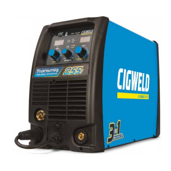
Transmig 255i OPERATING MANUAL 2.05 Description 2.07 Transporting Methods The Cigweld Transmig 255i is a self contained single WARNING phase multi process welding inverter that is capable ELECTRIC SHOCK can kill. DO NOT TOUCH live of performing GMAW/FCAW (MIG), MMAW (Stick) electrical parts. -
Page 18: Duty Cycle
Transmig 255i Transmig 255i OPERATING MANUAL 2.09 Duty Cycle The rated duty cycle of a Welding Power Source, is a statement of the time it may be operated at its rated welding current output without exceeding the temperature limits of the insulation of the component parts. To explain the 10 minute duty cycle period the following example is used. -
Page 19: Specifications
Transmig 220i Transmig 255i Transmig 255i OPERATING MANUAL 2.10 Specifications TRANSMIG 255i Description Transmig 255i Plant Part W1005255 Number Power Source Dimensions H435mm x W266mm x D617mm Power Source Weight 27kg Cooling Fan Cooled Welder Type Multi Process Inverter Power Source Australian Standard AS60974.1 / IEC60974-1 Number of Phases... - Page 20 Transmig 255i Transmig 255i OPERATING MANUAL NOTE 1 Due to variations that can occur in manufactured products, claimed performance, voltages, ratings, all capacities, measurements, dimensions and weights quoted are approximate only. Achievable capacities and ratings in use and operation will depend upon correct installation, use, applications, maintenance and service. NOTE 2 The Effective Input Current should be used for the determination of cable size &...
-
Page 21: Optional Accessories
Transmig 220i Transmig 255i Transmig 255i OPERATING MANUAL 2.11 Optional Accessories We recommend genuine CIGWELD products. The biggest range and best quality with guaranteed performance. Part Number Description W4013701 Tweco Professional Fusion 250 MIG Torch, 3.0 metre EURO OTWF212X3035 Tweco Professional Fusion 250 MIG Torch, 3.6 metre EURO OTWX212/3035 TWECO #2, 250A MIG torch, 3.6 metre EURO W4012300... - Page 22 Transmig 255i Transmig 255i OPERATING MANUAL TIG Electrodes Part Number Description 699846 Ceriated Electrode 1.6mm x 175mm AC/DC Grey (Pkt of 10) 699847 Ceriated Electrode 2.4mm x 175mm AC/DC Grey (Pkt of 10) 699848 Ceriated Electrode 3.2mm x 175mm AC/DC Grey (Pkt of 10) Table 2-4 Related Products Part Number...
-
Page 23: Installation
Transmig 220i Transmig 255i Transmig 255i OPERATING MANUAL SECTION 3: INSTALLATION G. The enclosure design of this power source meets 3.01 Environment the requirements of IP23S as outlined in AS60529. These units are designed for use in environments with This provides adequate protection against solid increased hazard of electric shock as outlined in AS objects (greater than 12mm), and direct protection 60974.1 and AS 1674.2. -
Page 24: Electromagnetic Compatibility
Transmig 255i Transmig 255i OPERATING MANUAL 7. The time of day that welding or other activities 3.05 Electromagnetic Compatibility are to be carried out. WARNING 8. The immunity of other equipment in the Extra precautions for Electromagnetic Compat- environment: the user shall ensure that other ibility may be required when this Welding equipment being used in the environment Power Source is used in a domestic situation. - Page 25 Transmig 220i Transmig 255i Transmig 255i OPERATING MANUAL 4. Equipotential Bonding Bonding of all metallic components in the welding installation and adjacent to it should be considered. However. Metallic components bonded to the work piece will increase the risk that the operator could receive a shock by touching the metallic components and the electrode at the same time.
- Page 26 Transmig 255i Transmig 255i OPERATING MANUAL This Page Intentionally Blank INSTALLATION Manual 0-5550...
-
Page 27: Operation
Transmig 220i Transmig 255i Transmig 255i OPERATING MANUAL SECTION 4: OPERATION 4.01 Overview Conventional operating procedures apply when using the Welding Power Source, i.e. connect work lead directly to workpiece and the electrode wire is fed via the MIG Torch (Consult the electrode wire manufacturers information for the correct polarity). - Page 28 Transmig 255i Transmig 255i OPERATING MANUAL 1. Power Indicator The power indicator is illuminated when the correct mains power is applied to the power source and when the ON/OFF switch located on the rear panel is in the ON position. 2.
- Page 29 Transmig 220i Transmig 255i Transmig 255i OPERATING MANUAL 4. Amperage Control (Wirespeed) The amperage control knob adjusts the amount of welding current delivered by the power source. In MMAW (stick) and GTAW (TIG) modes, the amperage control knob directly adjusts the power inverter to deliver the desired level of output current.
- Page 30 Transmig 255i Transmig 255i OPERATING MANUAL 9. Remote Control Socket The 8 pin Remote Control Socket is used to connect remote control devices to the welding power source. To make connections, align keyway, insert plug, and rotate threaded collar fully clockwise. Negative Trigger Switch Spool Gun Motor...
- Page 31 Transmig 220i Transmig 255i Transmig 255i OPERATING MANUAL When GMAW/FCAW (MIG) Mode is Selected In this mode the control knob is used to adjust the output voltage of the unit. The welding voltage is increased by turning the knob clockwise or decreased by turning the knob anti-clockwise. The optimum voltage level required will dependent on the type of welding application.
- Page 32 Transmig 255i Transmig 255i OPERATING MANUAL 13. Process Selection Control The process selection control is used to select the desired welding mode. Three modes are available, GMAW/FCAW (MIG), GTAW (Lift TIG) and MMAW (Stick) modes. Refer to section 5.09, 5.10 or 5.11 for FCAW/GMAW (MIG) set up details, section 6.02 for GTAW (TIG) set-up details or section 7.01 for MMAW (stick) set-up details.
- Page 33 Transmig 220i Transmig 255i Transmig 255i OPERATING MANUAL 17. On / Off Switch This Single Phase circuit breaker performs a dual function. It is used to turn the unit on/off and it will also trip in the event of a fault. WARNING When the front digital displays are lit, the machine is connected to the Mains supply voltage and the internal electrical components are at Mains voltage potential.
- Page 34 Transmig 255i Transmig 255i OPERATING MANUAL 22. Cooling Fan The Transmig 255i is fitted with a fan as needed feature. Fan as needed automatically switches the cooling fan off when it is not required. This has two main advantages; (1) to minimize power consumption, and (2) to minimise the amount of contaminants such as dust that are drawn into the power source.
-
Page 35: Mig (Gmaw) Welding
Transmig 220i Transmig 255i Transmig 255i OPERATING MANUAL SECTION 5: MIG (GMAW) WELDING 5.01 Shielding Gas Regulator/Flowmeter Operating Instructions WARNING This equipment is designed for use with welding grade (Inert) shielding gases only. Shielding Gas Regulator/Flowmeter Safety This regulator/flowmeter is designed to reduce and control high pressure gas from a cylinder or pipeline to the working pressure required for the equipment using it. - Page 36 Transmig 255i Transmig 255i OPERATING MANUAL User Responsibilities This equipment will perform safely and reliable only when installed, operated and maintained, and repaired in accordance with the instructions provided. Equipment must be checked periodically and repaired, replaced, or reset as necessary for continued safe and reliable performance. Defective equipment should not be used. Parts that are broken, missing, obviously worn, distorted, or contaminated should be replaced immediately.
- Page 37 Transmig 220i Transmig 255i Transmig 255i OPERATING MANUAL Operation With the regulator/flowmeter connected to cylinder or pipeline, and the adjustment screw/knob fully disengaged, pressurize as follows: 1. Stand to one side of regulator/flowmeter and slowly open the cylinder valve. If opened quickly, a sudden pressure surge may damage internal regulator/flowmeter parts.
-
Page 38: Attaching The Tweco Professional Fusion Mig Torch (Euro)
Transmig 255i Transmig 255i OPERATING MANUAL 5.02 Attaching the Tweco Professional Fusion MIG Torch (Euro) Fit the MIG Torch to the power source by pushing the MIG torch connector into the MIG torch adaptor and screwing the plastic torch nut clockwise to secure the MIG torch to the MIG torch adaptor. MIG Gun Adaptor MIG Gun Connector Art # A-10927... -
Page 39: Installing Handispool (200Mm Diameter)
Transmig 220i Transmig 255i Transmig 255i OPERATING MANUAL 5.04 Installing Handispool (200mm diameter) Remove the locking pin from the spool hub. Install the Handi Spool over the spool hub, locating the hole in the Handi Spool, with the alignment pin on the Spool Hub. -
Page 40: Inserting Wire Into The Wire Feed Mechanism
Transmig 255i Transmig 255i OPERATING MANUAL 5.05 Inserting Wire into the Wire Feed Mechanism Release the tension from the pressure roller by turning the adjustable wire drive tension screw in an anti- clockwise direction. Then to release the pressure roller arm push the tension screw toward the front of the machine which releases the pressure roller arm (Figure 5-6). -
Page 41: Feed Roller Pressure Adjustment
Transmig 220i Transmig 255i Transmig 255i OPERATING MANUAL 5.06 Feed Roller Pressure Adjustment The pressure (top) roller applies pressure to the grooved feed roller via an adjustable pressure screw. These devices should be adjusted to a minimum pressure that will provide satisfactory WIREFEED without slippage. If slipping occurs, and inspection of the wire contact tip reveals no wear, distortion or burn back jam, the conduit liner should be checked for kinks and clogging by metal flakes and swarf. -
Page 42: Wire Reel Brake
Transmig 255i Transmig 255i OPERATING MANUAL 5.08 Wire Reel Brake The wire reel hub incorporates a friction brake which is adjusted during manufacture for optimum braking. If it is considered necessary, adjustment can be made by turning the Thumb Screw inside the open end of the hub clockwise to tighten the brake. - Page 43 Transmig 220i Transmig 255i Transmig 255i OPERATING MANUAL I. Fit the welding grade shielding gas regulator/flowmeter to the shielding gas cylinder (refer to Section 5.01) then connect the shielding gas hose from the shielding gas regulator/flowmeter outlet to the quick connect Shielding Gas Inlet fitting gas on the rear of the Transmig 255i Power Source.
-
Page 44: Setup For Mig (Gmaw) Welding With Gasless Mig Wire
Transmig 255i Transmig 255i OPERATING MANUAL 5.10 Setup for MIG (GMAW) Welding with Gasless Mig Wire A. Fit the MIG Torch to the Power Source. (Refer to Section 5.02 Attaching the Tweco Fusion MIG Torch). B. Connect the Mig Torch polarity lead to the negative welding terminal (-). If in doubt, consult the electrode wire manufacturer. - Page 45 Transmig 220i Transmig 255i Transmig 255i OPERATING MANUAL 240VAC 15A Mains Supply Note: For Maximum duty cycle to be achieved, Supply Plug and Lead must be upgraded to 4mm Supply Lead & 25A Supply Plug. Refer to Specification Table on Page 2-5. MIG Gun Negative Welding Positive Welding...
-
Page 46: Setup For Spool Gun Mig (Gmaw) Welding With Gas Shielded Mig Wire
Transmig 255i Transmig 255i OPERATING MANUAL 5.11 Setup for SPOOL GUN MIG (GMAW) Welding with Gas Shielded Mig Wire A. Select MIG mode with the process selection control (refer to Section 4.02.13 for further information). B. Connect the Mig torch polarity lead to the positive welding terminal (+). If in doubt, consult the electrode wire manufacturer. -
Page 47: Mig (Gmaw/Fcaw) Basic Welding Technique
Transmig 220i Transmig 255i Transmig 255i OPERATING MANUAL 5.12 MIG (GMAW/FCAW) Basic Welding Technique Two different welding processes are covered in this section (GMAW and FCAW), with the intention of providing the very basic concepts in using the Mig mode of welding, where a welding gun is hand held, and the electrode (welding wire) is fed into a weld puddle, and the arc is shielded by an inert welding grade shielding gas or inert welding grade shielding gas mixture. - Page 48 Transmig 255i Transmig 255i OPERATING MANUAL Position of MIG Torch The angle of MIG torch to the weld has an effect on the width of the weld. Push Vertical Drag/Pull Art # A-07185_AB Figure 5-16 The welding gun should be held at an angle to the weld joint. (see Secondary Adjustment Variables below) Hold the gun so that the welding seam is viewed at all times.
- Page 49 Transmig 220i Transmig 255i Transmig 255i OPERATING MANUAL 10° to 20° Longitudinal Angle 10° Longitudinal Angle 30° to 60° 30° to 60° Transverse Transverse Angle Angle Direction of Travel Vertical Fillet Welds Art # A-08995 Figure 5-19 Direction of Travel 30°...
- Page 50 Transmig 255i Transmig 255i OPERATING MANUAL Secondary Adjustable Variables These variables cause changes in primary adjustable variables which in turn cause the desired change in the bead formation. They are: 1. Stick-out (distance between the end of the contact tube (tip) and the end of the electrode wire). Maintain at about 10mm stick-out.
- Page 51 Transmig 220i Transmig 255i Transmig 255i OPERATING MANUAL Establishing the Arc and Making Weld Beads Before attempting to weld on a finished piece of work, it is recommended that practice welds be made on a sample metal of the same material as that of the finished piece. The easiest welding procedure for the beginner to experiment with MIG welding is the flat position.
-
Page 52: Cigweld Mig Wire Selection Chart
Transmig 255i Transmig 255i OPERATING MANUAL 5.13 CIGWELD MIG Wire Selection Chart DESCRIPTION DIAMETER PACK PART NUMBER APPLICATION 0.6mm Handispool 5kg 721108 0.6mm Spool 15kg 720103 General purpose welding wire suitable for the 0.8mm Handispool 5kg 721109 all positional Gas Metal Arc Welding (GWAW) of mild and low alloy steels, used in general AUTOCRAFT LW1-6 0.8mm... -
Page 53: Mig (Gmaw/Fcaw) Welding Troubleshooting
Transmig 220i Transmig 255i Transmig 255i OPERATING MANUAL 5.14 MIG (GMAW/FCAW) Welding Troubleshooting Solving Problems Beyond the Welding Terminals The general approach to fix Gas Metal Arc Welding (GMAW) problems is to start at the wire spool then work through to the MIG torch. There are two main areas where problems occur with GMAW, Porosity and Inconsistent wire feed Solving Problems Beyond the Welding Terminals - Porosity When there is a gas problem the result is usually porosity within the weld metal. - Page 54 Transmig 255i Transmig 255i OPERATING MANUAL Solving Problems Beyond the Welding Terminals - Inconsistent Wire Feed Wire feeding problems can be reduced by checking the following points. FAULT CAUSE 1 Feed roller driven by motor in the Wire spool brake is too tight. cabinet slipped.
- Page 55 Transmig 220i Transmig 255i Transmig 255i OPERATING MANUAL Basic GMAW (MIG) Welding Troubleshooting FAULT CAUSE REMEDY 1 Undercut A Welding arc voltage too A Decrease voltage or increase the wire feed speed. high. B Incorrect torch angle B Adjust angle. C Excessive heat input C Increase the torch travel speed and/or decrease welding current by decreasing the voltage or...
- Page 56 Transmig 255i Transmig 255i OPERATING MANUAL This Page Intentionally Blank MIG (GMAW) WELDING 5-22 Manual 0-5550...
-
Page 57: Tig (Gtaw) Welding
Transmig 220i Transmig 255i Transmig 255i OPERATING MANUAL SECTION 6: TIG (GTAW) WELDING 6.01 Shielding Gas Regulator Operating Instructions WARNING This equipment is designed for use with welding grade (Inert) shielding gases only. Shielding Gas Regulator Safety This regulator is designed to reduce and control high pressure gas from a cylinder or pipeline to the working pressure required for the equipment using it. - Page 58 Transmig 255i Transmig 255i OPERATING MANUAL User Responsibilities This equipment will perform safely and reliable only when installed, operated and maintained, and repaired in accordance with the instructions provided. Equipment must be checked periodically and repaired, replaced, or reset as necessary for continued safe and reliable performance. Defective equipment should not be used. Parts that are broken, missing, obviously worn, distorted, or contaminated should be replaced immediately.
- Page 59 Transmig 220i Transmig 255i Transmig 255i OPERATING MANUAL Operation With the regulator connected to cylinder or pipeline, and the adjustment screw/knob fully disengaged, pressurize as follows: 1. Stand to one side of regulator and slowly open the cylinder valve. If opened quickly, a sudden pressure surge may damage internal regulator parts.
-
Page 60: Setup For Tig (Gtaw) Welding
Transmig 255i Transmig 255i OPERATING MANUAL 6.02 Setup for TIG (GTAW) Welding A. Connect the TIG Torch to the negative welding terminal (-). Welding current flows from the power source via Dinse terminals. It is essential, however, that the male plug is inserted and turned securely to achieve a sound electrical connection. - Page 61 Transmig 220i Transmig 255i Transmig 255i OPERATING MANUAL 240VAC 15A Mains Supply Note: For maximum duty cycle to be achieved, Supply Plug and Lead must be upgraded to 4mm Supply Lead & 25A Supply Plug. Refer to Specification Table on Page 2-5. Connect to shielding gas Positive Welding regulator/flowmeter...
-
Page 62: Tig (Gtaw) Basic Welding Technique
Transmig 255i Transmig 255i OPERATING MANUAL 6.03 TIG (GTAW) Basic Welding Technique Gas Tungsten Arc Welding (GTAW) or TIG (Tungsten Inert Gas) as it is commonly referred to, is a welding process in which fusion is produced by an electric arc that is established between a single tungsten (non- consumable) electrode and the work piece. - Page 63 Transmig 220i Transmig 255i Transmig 255i OPERATING MANUAL Tungsten Electrode Types Electrode Type Welding Application Features Colour Code (Ground Finish) AC & DC welding Longer life, More of mild steel, stable arc, Easier stainless steel, Ceriated 2% starting, Wider current Grey copper, aluminium, range, Narrower more...
-
Page 64: Tig (Gtaw) Welding Problems
Transmig 255i Transmig 255i OPERATING MANUAL 6.04 TIG (GTAW) Welding Problems FAULT CAUSE REMEDY 1 Excessive bead build up or Welding current is too Increase weld current and/or faulty joint poor penetration or poor preparation. fusion at edges of weld. 2 Weld bead too wide and Welding current is too Decrease weld current. - Page 65 Transmig 220i Transmig 255i Transmig 255i OPERATING MANUAL 7 Dirty weld pool A Electrode contaminated A Clean the electrode by grinding off the by contact with work contaminates. piece or filler rod material. B Work piece surface has B Clean surface. foreign material on it.
- Page 66 Transmig 255i Transmig 255i OPERATING MANUAL This Page Intentionally Blank TIG (GTAW) WELDING 6-10 Manual 0-5550...
-
Page 67: Manual Arc (Mmaw) Welding
Transmig 220i Transmig 255i Transmig 255i OPERATING MANUAL SECTION 7: MANUAL ARC (MMAW) WELDING 7.01 Setup for STICK (MMAW) Welding A. Connect the Electrode Holder lead to the positive welding terminal (+). If in doubt, consult the electrode manufacturer. Welding current flows from the Power Source via Dinse type terminals. It is essential, however, that the male plug is inserted and turned securely to achieve a sound electrical connection. -
Page 68: Stick (Mmaw) Basic Welding Technique
Transmig 255i Transmig 255i OPERATING MANUAL 7.02 Stick (MMAW) Basic Welding Technique Size of Electrode The electrode size is determined by the thickness of metals being joined and can also be governed by the type of welding machine available. Small welding machines will only provide sufficient current (amperage) to run the smaller size electrodes. - Page 69 Transmig 220i Transmig 255i Transmig 255i OPERATING MANUAL Art # A-07687 Figure 7-2: Flat Position, Down Hand Butt Weld Art # A-07688 Figure 7-3: Flat Position, Gravity Fillet Weld Art # A-07689 Figure 7-4: Horizontal Position, Butt Weld Art # A-07690 Figure 7-5: Horizontal-Vertical (HV) Position Art A-07691 Figure 7-6: Vertical Position, Butt Weld...
- Page 70 Transmig 255i Transmig 255i OPERATING MANUAL Art# A-07693 Figure 7-8: Overhead Position, Butt Weld Art # A-07694 Figure 7-9: Overhead Position, Fillet Weld Joint Preparations In many cases, it will be possible to weld steel sections without any special preparation. For heavier sections and for repair work on castings, etc., it will be necessary to cut or grind an angle between the pieces being joined to ensure proper penetration of the weld metal and to produce sound joints.
- Page 71 Transmig 220i Transmig 255i Transmig 255i OPERATING MANUAL Arc Welding Technique - A Word to Beginners For those who have not yet done any welding, the simplest way to commence is to run beads on a piece of scrap plate. Use mild steel plate about 6.0mm thick and a 3.2mm electrode. Clean any paint, loose scale or grease off the plate and set it firmly on the work bench so that welding can be carried out in the downhand position.
- Page 72 Transmig 255i Transmig 255i OPERATING MANUAL Arc Length The securing of an arc length necessary to produce a neat weld soon becomes almost automatic. You will find that a long arc produces more heat. A very long arc produces a crackling or spluttering noise and the weld metal comes across in large, irregular blobs.
- Page 73 Transmig 220i Transmig 255i Transmig 255i OPERATING MANUAL Heavy plate will require several runs to complete the joint. After completing the first run, chip the slag out and clean the weld with a wire brush. It is important to do this to prevent slag being trapped by the second run.
- Page 74 Transmig 255i Transmig 255i OPERATING MANUAL C. Vertical Welds 1. Vertical Up Tack weld a three feet length of angle iron to your work bench in an upright position. Use a 3.2mm Ferrocraft 21 electrode and set the current at 100 amps. Make yourself comfortable on a seat in front of the job and strike the arc in the corner of the fillet.
- Page 75 Transmig 220i Transmig 255i Transmig 255i OPERATING MANUAL 2. Vertical Down The Ferrocraft 21 electrode makes welding in this position particularly easy. Use a 3.2mm electrode at 100 amps. The tip of the electrode is held in light contact with the work and the speed of downward travel is regulated so that the tip of the electrode just keeps ahead of the slag.
- Page 76 Transmig 255i Transmig 255i OPERATING MANUAL Distortion Distortion in some degree is present in all forms of welding. In many cases it is so small that it is barely perceptible, but in other cases allowance has to be made before welding commences for the distortion that will subsequently occur.
- Page 77 Transmig 220i Transmig 255i Transmig 255i OPERATING MANUAL Overcoming Distortion Effects There are several methods of minimizing distortion effects. A. Peening This is done by hammering the weld while it is still hot. The weld metal is flattened slightly and because of this the tensile stresses are reduced a little.
- Page 78 Transmig 255i Transmig 255i OPERATING MANUAL Art # A-07709 Figure 7-24: Examples of Distortion Art # A-07710_AB Block Sequence. The spaces between the welds are filled in when the welds are cool. Figure 7-25: Welding Sequence Art # A-07711_AB Figure 7-26: Step back Sequence Art # A-07712 Figure 7-27: Chain Intermittent Welding Art # A-07713_AB...
-
Page 79: Electrode Selection Chart
Transmig 220i Transmig 255i Transmig 255i OPERATING MANUAL 7.03 Electrode Selection Chart CIGWELD Electrode Selection Chart Description Diameter Pack Part No. Application 2.5mm 322135 2.5mm 2.5kg 612182 General purpose electrode suitable for all positional Satincraft 13 3.2mm 322136 welding and galvanised steel. 3.2mm 2.5kg 612183... -
Page 80: Stick (Mmaw) Welding Troubleshooting
Transmig 255i Transmig 255i OPERATING MANUAL 7.04 Stick (MMAW) Welding Troubleshooting FAULT CAUSE REMEDY 1 Welding current ARC FORCE control knob Reduce the ARC FORCE control knob until varying is set at a value that welding current is reasonably constant while causes the welding current prohibiting the electrode from sticking to the to vary excessively with... - Page 81 Transmig 220i Transmig 255i Transmig 255i OPERATING MANUAL FAULT CAUSE REMEDY 5 Portions of the A Small electrodes used on A Use larger electrodes and preheat the plate. weld run do not heavy cold plate. fuse to the surface B Welding current is too low. B Increase welding current. of the metal or C Wrong electrode angle.
- Page 82 Transmig 255i Transmig 255i OPERATING MANUAL This Page Intentionally Blank. MANUAL ARC (MMAW) WELDING 7-16 Manual 0-5550...
-
Page 83: Routine Service Requirements And Power Source Problems
Transmig 220i Transmig 255i Transmig 255i OPERATING MANUAL SECTION 8: ROUTINE SERVICE REQUIREMENTS AND POWER SOURCE PROBLEMS 8.01 Routine Service and Calibration Requirements WARNING There are extremely dangerous voltage and power levels present inside this Inverter Power Source. Do not attempt to open or repair unless you are an accredited CIGWELD Service Provider. - Page 84 Transmig 255i Transmig 255i OPERATING MANUAL C. Earthing The resistance shall not exceed 1Ω between any metal of a power source where such metal is required to be earthed, and - 1. The earth terminal of a fixed power source; or 2.
- Page 85 Transmig 220i Transmig 255i Transmig 255i OPERATING MANUAL Power Source Calibration A. Schedule Output testing of all Cigweld Inverter Power Sources and applicable accessories shall be conducted at regular intervals to ensure they fall within specified levels. Calibration intervals shall be as outlined below - 1.
-
Page 86: Cleaning The Welding Power Source
Transmig 255i Transmig 255i OPERATING MANUAL 8.02 Cleaning the Welding Power Source WARNING There are extremely dangerous voltage and power levels present inside this Inverter Power Source. Do not attempt to open or repair unless you are an accredited CIGWELD Service Provider. Disconnect the Welding Power Source from the Mains Supply Voltage before disassembling. - Page 87 Transmig 220i Transmig 255i Transmig 255i OPERATING MANUAL 3 Mains Supply Voltage is A Power source is not in the A Set the power source to LIFT TIG On, the On/Off switch on correct mode of operation. mode. Refer to Section 4.02.13. the rear panel is in the On B Work Lead is not connected B Ensure that the Work Lead is...
- Page 88 Transmig 255i Transmig 255i OPERATING MANUAL 8 Inconsistent wire feed. A Worn or dirty contact tip. A Replace if necessary. B Worn feed roll. B Replace. C Excessive brake tension on C Reduce brake tension on spool wire reel hub. D Worn, kinked or dirty con- D Clean or replace conduit liner duit liner...
-
Page 89: Key Spare Parts
Transmig 220i Transmig 255i Transmig 255i OPERATING MANUAL SECTION 9: KEY SPARE PARTS 9.01 Tweco Fusion 250 Mig Torch MIG Torch Part No: W4013701, 3 metre A-09659_AB Figure 9-1 TWECO FUSION MIG TORCH PARTS ITEM PART NO. DESCRIPTION OTW22/50 Nozzle 13mm OTW22/62 Nozzle 16mm OTW14/23... -
Page 90: Power Source
Transmig 255i Transmig 255i OPERATING MANUAL 9.02 Power Source Art # A-13935 Figure 9-2 TRANSMIG 255i POWER SOURCE SPARE PARTS Item Part Number Description W7005650 PCB Power W7005651 PCB Control W7005652 PCB Display W7005607 PCB Spool Gun W7005653 PCB Burnback W7005654 Wiredrive Assembly W7004906 Feed Roll Retaining Thumbscrew Feed Roll 0.9/1.2mm V groove (fitted as standard) -
Page 91: Appendix: Transmig 255I Circuit Diagram
Transmig 220i Transmig 255i Transmig 255i OPERATING MANUAL APPENDIX: TRANSMIG 255i CIRCUIT DIAGRAM +15V +15V +24V +24V -24V -24V +24V +24V Gas control OK=0V OK=0V OUT+ OUT- -15V Manual 0-5550 APPENDIX... - Page 92 Transmig 255i Transmig 255i OPERATING MANUAL This Page Intentionally Blank APPENDIX Manual 0-5550...
-
Page 93: Cigweld - Limited Warranty Terms
OPERATING MANUAL CIGWELD - LIMITED WARRANTY TERMS LIMITED WARRANTY: CIGWELD Pty Ltd, An ESAB Brand, hereafter, “CIGWELD” warrants to customers of its authorized distributors hereafter “Purchaser” that its products will be free of defects in workmanship or material. Should any failure to conform to this warranty appear within the time period applicable to the CIGWELD products as stated below, CIGWELD shall, upon notification thereof and substantiation that the product has been stored, installed, operated, and maintained in accordance with CIGWELD’s specifications, instructions, recommendations... - Page 94 Transmig 255i Transmig 255i OPERATING MANUAL WARRANTY SCHEDULE – TRANSMIG 255i WARRANTY WARRANTY PERIOD – (Parts and Labour) Transmig 255i Inverter Power Source 3 Years ACCESSORIES WARRANTY PERIOD MIG torch, electrode holder lead and work 3 Months lead. MIG torch consumable items. Gas regulator/flowmeter (excluding seat assembly, pressure gauges, elastomer seals and 1 Year...
- Page 95 Transmig 220i Transmig 255i Transmig 255i OPERATING MANUAL This Page Intentionally Blank...
- Page 96 CIGWELD Pty Ltd CIGWELD An ESAB Brand Singapore Malaysia Indonesia ESAB Asia Pacific 71 Gower Street, Preston VIC 3072 Australia No. 14 Jalan Teknologi 3/1 JI. Pulogadung No. 45 38 Joo Koon Circle Selangor Science Park 1 Kawasan Industri Pulogadung...
Need help?
Do you have a question about the CIGWELD Transmig 255i and is the answer not in the manual?
Questions and answers