Table of Contents
Advertisement
Advertisement
Table of Contents

Related Manuals for ESAB Migmaster 275


Summary of Contents for ESAB Migmaster 275
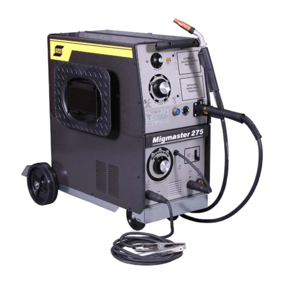
- Page 1 Migmaster 275 Welding Package Instruction Manual 0558008552 07 / 2009...
-
Page 2: User Responsibility
Be sure thIs InforMatIon reaches the operator. You can get extra copIes through Your supplIer. cautIon these InstructIons are for experienced operators. If you are not fully familiar with the principles of operation and safe practices for arc welding and cutting equipment, we urge you to read our booklet, “precautions and safe practices for arc Welding, cutting, and gouging,”... -
Page 3: Table Of Contents
2 - IntroDuctIon ............................17 GENERAL ........................................17 RECEIVING-HANDLING ....................................17 DESCRIPTION, Available Packages/Contents ............................17 OPTIONAL ACCESSORIES ..................................18 MIGMASTER 275 / GUNMASTER 250 WEAR PARTS .........................19 sectIon 3 - InstallatIon ............................21 LOCATION ........................................21 ELECTRICAL INPUT CONNECTIONS ..............................21 SECONDARY OUTPUT CONNECTIONS ..............................24 TORCH CONNECTIONS ....................................25 WIRE FEEDER MECHANISM ..................................25... - Page 4 taBle of content...
-
Page 5: Section No
sectIon 1 safetY precautIons safety precautions safety - english WarnIng: These Safety Precautions are fIres anD explosIons -- heat from for your protection. They summarize pre- flames and arcs can start fires. hot cautionary information from the references slag or sparks can also cause fires and listed in Additional Safety Information sec- explosions. -
Page 6: Safety Precautions
sectIon 1 safetY precautIons 1. Be sure the power source frame (chassis) is con- 3. Welders should use the following procedures to nected to the ground system of the input power. minimize exposure to EMF: 2. Connect the workpiece to a good electrical A. - Page 7 sectIon 1 safetY precautIons 5. WarnIng: this product, when used for welding 1. Always have qualified personnel perform the instal- or cutting, produces fumes or gases lation, troubleshooting, and maintenance work. which contain chemicals known to Do not perform any electrical work unless you are the state of california to cause birth qualified to perform such work.
- Page 8 sectIon 1 safetY precautIons 5. AWS C5.5 - "Recommended Practices for Gas Tung- sten Arc Welding“ 6. AWS C5.6 - "Recommended Practices for Gas Metal Arc Welding"“ 7. AWS SP - "Safe Practices" - Reprint, Welding Hand- book. 8. ANSI/AWS F4.1, "Recommended Safe Practices for Welding and Cutting of Containers That Have Held Hazardous Substances."...
- Page 9 seccIon 1 segurIDaD safety - spanish La escoria puede estar caliente y desprenderse con velocidad. Personas cercanas deberán usar gafas aDVertencIa: Estas Precauciones de Se- de seguridad y careta protectora. guridad son para su protección. Ellas hacen resumen de información proveniente de las fuego Y explosIones -- el calor de referencias listadas en la sección "Información Adi- las flamas y el arco pueden ocacionar...
- Page 10 seccIon 1 segurIDaD 1. Asegúrese de que el chasis de la fuente de poder 3. Los soldadores deberán usar los siguientes proced- esté conectado a tierra através del sistema de imientos para minimizar exponerse al EMF: electricidad primario. 2. Conecte la pieza de trabajo a un buen sistema de A.
- Page 11 seccIon 1 segurIDaD 5. aDVertencIa-- este producto cuando se uti- 1. Siempre tenga personal cualificado para efec- liza para soldaduras o cortes, tuar l a instalación, diagnóstico, y mantenimiento produce humos o gases, los del equipo. No ejecute ningún trabajo eléctrico a cuales contienen químicos menos que usted esté...
- Page 12 seccIon 1 segurIDaD sIgnIfIcaDo De los sIMBolos -- según usted avanza en la lectura de este folleto: los símbolos sig- nifican ¡atención! ¡esté alerta! se trata de su seguridad. significa riesgo inmediato que, de no ser evadido, puede resultar inmediatamente en serio daño personal o la muerte.
- Page 13 sectIon 1 sÉcurItÉ safety - french IncenDIes et explosIons -- la chaleur provenant des flammes ou de aVertIsseMent : Ces règles de sécurité l'arc peut provoquer un incendie. le ont pour but d'assurer votre protection. Ils récapitulent les informations de précaution laitier incandescent ou les étincelles provenant des références dans la section peuvent également provoquer un...
- Page 14 sectIon 1 sÉcurItÉ 1. Assurez-vous que le châssis de la source 3. Les soudeurs doivent suivre les procédures suivantes d'alimentation est branché au système de mise à pour minimiser l'exposition aux champs électriques la terre de l'alimentation d'entrée. et magnétiques : 2.
- Page 15 sectIon 1 sÉcurItÉ 5. aVertIsseMent : ce produit, lorsqu'il est utilisé entretIen De l'ÉQuIpeMent -- un équipe- dans une opération de soudage ou de ment entretenu de façon défectueuse ou coupage, dégage des vapeurs ou des inadéquate peut causer des blessures gaz contenant des chimiques consid- graves ou mortelles.
- Page 16 sectIon 1 sÉcurItÉ sIgnIfIcatIon Des sYMBoles ce symbole, utilisé partout dans ce manuel, signifie "attention" ! soyez vigilant ! Votre sécurité est en jeu. Danger signifie un danger immédiat. la situation peut entraîner des blessures graves ou mortelles. aVertIsseMent signifie un danger potentiel qui peut entraîner des blessures graves ou mortelles.
-
Page 17: Section 2 - Introduction
® to deliver superior performance using short arc, spray arc, as Push-Pull Ready console is set up to accept the ESAB MIG-41A Push-Pull well as flux and metal cored wires ranging from .023 (.6mm), gun (order gun, gun fittings and package accessories separately) to 1/16"... -
Page 18: Optional Accessories
2.4.4 Mt-250sg and st-23a spool gun This easy-to-install, plug-in module enables the use of The Migmaster 275 unit is equipped with a built-in control an adjustable Anti-Stick feature that allows adjustment that accepts the MT-250SG or ST-23A spool gun. These... -
Page 19: Migmaster 275 / Gunmaster 250 Wear Parts
* All Liners supplied 15 ft. and must be trimmed to fit the gun per instructions. ** Requires Jumper Liner Sleeve 0558003050 Bold indicates "as supplied from factory". taBle 2.2 MIgMaster 275 / gunMaster 250 Wear parts gunMaster-250 stanDarD DutY noZZles & tIp aDapter w/ Std Contact Tips w/ HD Contact Tips 3/8"... - Page 20 sectIon 2 IntroDuctIon...
-
Page 21: Section 3 - Installation
sectIon 3 InstallatIon 3.1 locatIon (figure 3.1) Proper installation permits free air movement into and out Before making electrical input connections to the weld- of the unit and minimizes exposure to dust, dirt, moisture, ing machine, “Machinery lockout procedures” must be and corrosive vapors. - Page 22 sectIon 3 InstallatIon Figure 3.2A illustrates wiring to a single phase system and 3.2.4a connectIng for 208 Vac Input Figure 3.2B illustrates wiring to a three phase system. Fig. 3.3A shows the 230v and 208v connections for the 208/230 dual voltage model. Change over is made by remov- The 208/230/380/400/460/575 primary input voltage unit is ing the right side panel below the wire feed compartment provided with a three conductor primary input cable without...
- Page 23 sectIon 3 InstallatIon switch (Fig. 3.3C.) to expose the terminals and disconnect the 208 Vac lead from the top of the switch as shown in Fig. 3.3A. Insulate the 208 Vac lead that was removed from the the terminal labeled grD is connected to the welding power switch with sleeving or approved electrical tape machine chassis and is for ground purposes only.
-
Page 24: Secondary Output Connections
Board for 208/230/380/400/460/575Volt Models 3.3 seconDarY output connectIons The Migmaster 275 Welding System is completely self- figure 3.6 short arc, spray arc solid Wire and fluxcore contained so that the front panel welding gun fittings are - Dc electrode positive steep slope for a crisp internally connected to the electrode polarity cable on the driving arc with higher output power. -
Page 25: Torch Connections
sectIon 3 InstallatIon 3.4 torch connectIons The GunMaster 250 supplied standard with the Migmaster Install a spool of welding wire on the hub as follows: 275 System, is provided with a NAS-type connector which connects directly to the gun receptacle on the front panel. A. -
Page 26: Connection Of The Shield Gas
50 cfh through the torch. Migmaster 275 for leakage. Correct any leaks before starting work. i. If work is to be stopped for a half-hour or more, or... -
Page 27: Installing Optional Burn Back Module
sectIon 3 InstallatIon The proper operation of this equipment is to a large extent dependent on the use of welding cables and connections which are in good condition and of adequate size. InstallIng optIonal Burn BacK MoDule a. Remove lower blank-cover plate from upper-right front panel of power supply. - Page 28 sectIon 3 InstallatIon...
-
Page 29: Section 4 - Operation
sectIon 4 operatIon controls (see figure 4.1) 4.1.2 Voltage control (coarse range selector and fine adjustment range selector) 4.1.1 poWer sWItch Voltage control is by means of two high current tap switches The front panel Power Switch energizes the primary of the which connect the rectifier bridge to eight secondary main transformer, the control circuits, the wire feed circuit, taps. - Page 30 sectIon 4 operatIon The fIne Voltage aDJustMent selector is an eight- The fIne Voltage aDJustMent selector is an eight- The fIne Voltage aDJustMent selector is an eight- Dial setting Dial setting Wire speed IpM Wire speed IpM position switch for selecting the exact amount of arc volt- position switch for selecting the exact amount of arc volt- position switch for selecting the exact amount of arc volt- age (or heat) to be applied to the weld arc.
-
Page 31: Process Setup
The Migmaster system is rated at 50% duty cycle. The Migmaster 275 is equipped with a built-in control for the This means that the equipment can be safely operated at Spool Gun which operates via the amphenol control receptacle 250 amperes for five minutes out of every 10. -
Page 32: Operating Safety Procedures
sectIon 4 operatIon 4.2.5 Volt/aMpere curVes (figure 4.6) The actual operating point of load Voltage and Current is determined by type of process, electrode, shield gas, The Volt/Ampere curves show the output Voltage available wire feed speed, and operating technique. at any given output current for the various Voltage Selector positions in each range low, medium, and high. - Page 33 sectIon 4 operatIon D. Correct size wire accessories have been installed Avoid gas leaks in a confined space, as the leaked gas on the wire feeder, drive gears are meshed, wire can dangerously reduce oxygen concentration in the pressure set, and guide tube is installed for type breathing air.
-
Page 34: Welding Operation
sectIon 4 operatIon Connect cables for “DCEP”; torch polarity cable to C. To start the weld, hold the torch so the welding wire is the POS (+) output Steep Slope receptacle and the approximately 1/4-in. from the work, then press the “Work”... - Page 35 4 operatIon figure 4.8 angle of Welding Wire with Joint MIGMASTER 275 SETUP GUIDE OPTIONAL DIGITAL METER TO SET WELD PARAMETERS MODULE 1. Find the type and thickness of material to be welded. Set recommended Slope Tap (Steep or Flat).
- Page 36 sectIon 4 operatIon taBle 4.3 Weld condition setup guide - aluminum taBle 4.4 Weld condition setup guide - stainless steel...
-
Page 37: Section 5 - Service
sectIon 5 serVIce 5.1 MaIntenance If uninsulated cable and parts are not replaced, an arc caused by a bared cable or part touching a grounded surface may damage unprotected eyes or start a fire. Be sure the branch circuit or main disconnect switch is Body contact with a bared cable, connector, or uncovered off or electrical input circuit fuses are removed before conductor can shock, possible fatally. -
Page 38: Troubleshooting
sectIon 5 serVIce 5.2.1c transforMer Occasional blowing out of the dust and dirt from around to avoid shock, do not touch electrode wire or parts in the transformer is recommended. This should be done periodically depending upon the location of the unit and contact with it, or uninsulated cable or connections. - Page 39 ESAB representative. 2. No welding power. a. Thermostat has opened. a. Wait 15 minutes with fan running. If still no power, contact ESAB repre- sentative. b. Shorted diode in main rectifier. b. Check diodes and replace if req’d. c. Open in wiring c.
- Page 40 sectIon 5 serVIce WelD conDItIon possIBle cause reMeDY b. Welding cables too long or too b. Use correct cable size. small. c. Loose connection. c. Check all welding cable connections. d. Malfunctioning capacitor bank. d. Check capacitors for low leakage resistance. 6.
- Page 41 sectIon 5 serVIce WelD conDItIon possIBle cause reMeDY 13. Wire sticks into the puddle a. Incorrect termination technique. a. Pull the gun back slightly after at the end of weld. releasing the gun trigger. Install and adjust optional Burn Back module. b.
- Page 42 sectIon 5 serVIce...
-
Page 43: Section 6 - Replacement Parts
To ensure proper operation, it is recommended that only genuine ESAB parts and products be used with this equipment. The use of non-ESAB parts may void your warranty. Replacement parts may be ordered from your ESAB Distributor. -
Page 44: Replacement Parts
6 replaceMent parts 6, 7 2, 3 fIgure 6.5b Migmaster 275 lexan huB KIt IteM QtY. part cKt. reQ. DescrIptIon (huB KIt) DesIg. 0558002993 D-Shaft, Wirefeeder, 5.75L 61341133 Screw, HC, .375-16 x 1.00 64302037 Washer, Lock, .375 0558002992 Bracket, Spool Support... - Page 45 See Table 2.2 (Subsection 2.5) See Table 2.2 (Subsection 2.5) See Table 2.2 (Subsection 2.5) 2-roll WIre DrIVe sYsteM Item no. esaB part number Description 0558008450 2R-Wire Drive System (includes Items 2 thru 10) 0558008593 Gear Adaptor, Upper 0558008594 Gear Adaptor, Lower...
- Page 46 sectIon 6 replaceMent parts...
-
Page 47: Revision History
reVIsIon hIstorY 12 / 2008 - Initial release 04 / 2009 - Added "Burn Back" phrase in several locations and deleted redundant or unneeded information per Bob Bitzky / George Magee redlines. 06 / 2009 - Updates made per J. Magee. 07 / 2009 - Added stainless and aluminum setup charts per Bob Bitzky. - Page 58 Welding & cutting products, florence, sc Welding equipment coMMunIcatIon guIDe - custoMer serVIces CUSTOMER SERVICE QUESTIONS: Telephone: (800)362-7080 / Fax: (800) 634-7548 Hours: 8:00 AM to 7:00 PM EST Order Entry Product Availability Pricing Order Information Returns ENGINEERING SERVICE:...
Need help?
Do you have a question about the Migmaster 275 and is the answer not in the manual?
Questions and answers