ESAB MigMaster 250 Instruction Manual
Hide thumbs
Also See for MigMaster 250:
- Instructions manual (36 pages) ,
- Instruction manual (56 pages)
Table of Contents
Advertisement
Advertisement
Table of Contents

Related Manuals for ESAB MigMaster 250


Summary of Contents for ESAB MigMaster 250
- Page 1 MigMaster 250 Welding Package Instruction Manual F15-087-P 03/2008...
- Page 2 Be sure thIs InForMatIon reaches the oPerator. You can get extra coPIes through Your suPPlIer. cautIon these InstructIons are for experienced operators. If you are not fully familiar with the principles of operation and safe practices for arc welding and cutting equipment, we urge you to read our booklet, “Precautions and safe Practices for arc Welding, cutting, and gouging,”...
-
Page 3: Table Of Contents
taBle oF content SECTION NO........................................PAGE NO. SECTION 1 - SAFETY PRECAUTIONS ..................................3 SECTION 2 - INTRODUCTION ....................................11 GENERAL ........................................11 RECEIVING-HANDLING ....................................11 DESCRIPTION, Available Packages/Contents ............................11 OPTIONAL ACCESSORIES ..................................12 SAFETY ..........................................14 SECTION 3 - INSTALLATION ....................................15 LOCATION ........................................15 ELECTRICAL INPUT CONNECTIONS ..............................15 SECONDARY OUTPUT CONNECTIONS ..............................18 TORCH CONNECTIONS ....................................18 WIRE FEEDER MECHANISM ..................................18... - Page 4 taBle oF content...
-
Page 5: Section No
sectIon 1 saFetY PrecautIons safety Precautions safety - english WarnIng: these safety Precautions are for your protection. they summarize precaution- ary information from the references FIres anD exPlosIons -- heat from listed in additional safety Information flames and arcs can start fires. hot section. - Page 6 sectIon 1 saFetY PrecautIons 1. Be sure the power source frame (chassis) is con- 3. Welders should use the following procedures to nected to the ground system of the input power. minimize exposure to EMF: 2. Connect the work piece to a good electrical A.
- Page 7 sectIon 1 saFetY PrecautIons 5. WarnIng: this product, when used for welding 1. Always have qualified personnel perform the instal- or cutting, produces fumes or gases lation, troubleshooting, and maintenance work. which contain chemicals known to Do not perform any electrical work unless you are the state of california to cause birth qualified to perform such work.
- Page 8 sectIon 1 saFetY PrecautIons 5. AWS C5.5 - "Recommended Practices for Gas Tung- sten Arc Welding“ 6. AWS C5.6 - "Recommended Practices for Gas Metal Arc Welding"“ 7. AWS SP - "Safe Practices" - Reprint, Welding Hand- book. 8. ANSI/AWS F4.1, "Recommended Safe Practices for Welding and Cutting of Containers That Have Held Hazardous Substances."...
-
Page 9: Section 1 - Safety Precautions
sectIon 1 segurIDaD safety - spanish la escoria puede estar caliente y desprenderse con velocidad. Personas cercanas deberán usar aDVertencIa: estas Precauciones de gafas de seguridad y careta protectora. seguridad son para su protección. ellas hacen resumen de información prove- Fuego Y exPlosIones -- el calor de niente de las referencias listadas en la sección las flamas y el arco pueden ocacionar... - Page 10 sectIon 1 segurIDaD 1. Asegúrese de que el chasis de la fuente de poder 3. Los soldadores deberán usar los siguientes proced- esté conectado a tierra através del sistema de imientos para minimizar exponerse al EMF: electricidad primario. 2. Conecte la pieza de trabajo a un buen sistema de A.
- Page 11 sectIon 1 segurIDaD 5. aDVertencIa-- este producto cuando se uti- 1. Siempre tenga personal cualificado para efec- liza para soldaduras o cortes, tuar l a instalación, diagnóstico, y mantenimiento produce humos o gases, los del equipo. No ejecute ningún trabajo eléctrico a cuales contienen químicos menos que usted esté...
- Page 12 sectIon 1 segurIDaD sIgnIFIcaDo De los sIMBolos -- según usted avanza en la lectura de este folleto: los símbolos sig- nifican ¡atención! ¡esté alerta! se trata de su seguridad. significa riesgo inmediato que, de no ser evadido, puede resultar inmediatamente en serio daño personal o la muerte.
- Page 13 sectIon 1 sÉcurItÉ IncenDIes et exPlosIons -- la safety - French chaleur provenant des flammes ou de aVertIsseMent : ces règles de sécurité l'arc peut provoquer un incendie. le ont pour but d'assurer votre protection. laitier incandescent ou les étincelles Ils récapitulent les informations de pré- peuvent également provoquer un caution provenant des références dans...
- Page 14 sectIon 1 sÉcurItÉ 1. Assurez-vous que le châssis de la source 3. Les soudeurs doivent suivre les procédures suivantes d'alimentation est branché au système de mise à pour minimiser l'exposition aux champs électriques la terre de l'alimentation d'entrée. et magnétiques : 2.
- Page 15 sectIon 1 sÉcurItÉ 5. aVertIsseMent : ce produit, lorsqu'il est utilisé entretIen De l'ÉQuIPeMent -- un équipe- dans une opération de soudage ou de ment entretenu de façon défectueuse ou coupage, dégage des vapeurs ou des inadéquate peut causer des blessures gaz contenant des chimiques consid- graves ou mortelles.
- Page 16 sectIon 1 sÉcurItÉ sIgnIFIcatIon Des sYMBoles ce symbole, utilisé partout dans ce manuel, signifie "attention" ! soyez vigilant ! Votre sécurité est en jeu. Danger signifie un danger immédiat. la situation peut entraîner des blessures graves ou mortelles. aVertIsseMent signifie un danger potentiel qui peut entraîner des blessures graves ou mortelles.
-
Page 17: Section 2 - Introduction
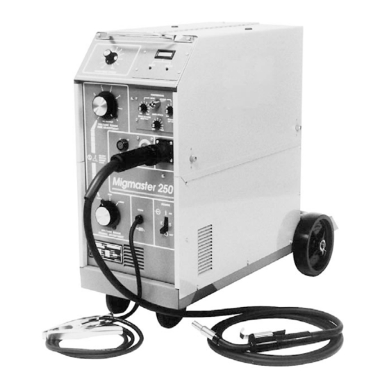
This manual has been prepared especially for use in famil- iarizing personnel with the design, installation, operation, - One (1), Migmaster 250 Power Supply/Wire Feeder equipped with maintenance, and troubleshooting of this equipment. a dual-groove feed roll (for .035/.045 wire), a 6'-0" ft. primary input All information presented here in should be given care- power cable and plug (plug is installed for 208/230-V. -
Page 18: Optional Accessories
2.4.1 sPot/stItch/antI-stIcK MoDule, P/n 32858. The Migmaster 250 System can be used to weld hard and This easy-to-install, plug-in module mounts in place of aluminum wire with an optional ST-23A spool-gun torch. the lower blank cover plate of the upper-right front panel An optional spot/stitch control allows a welder to spot or stitch weld within a range of 0.4 to 3.5 seconds. - Page 19 (see F-14-353). Steel & Flux Core P/N 999625. 0558001862 Lincoln 0558001675 ..023 x 10,12,15' Liner* The Migmaster 250 unit is equipped with a built-in control 0558002313 L-TEC 2.4.2 DIgItal Volt/aMMeter MoDule, 37031 ..030 x 10,12,15' Liner* for the ST-23A Spool-On-Gun welding torch. The ST-23A is P/n 32857.
-
Page 20: Safety
37034 ..3/32 x 10,12,15' Liner* Short Circuit (Short Arc) Welding short arc. Typical metal transfer is accomplished by 0558001815 ....Trigger Lead 7”, ESAB 0558002140 ..3/32 x 25' Liner drops of molten metal with bigger diameter than the Tip stick out 1/8”... -
Page 21: Section 3 - Installation
sectIon 3 InstallatIon 3.1 locatIon (Figure 3.1) A proper installation site should be selected for the welding machine, if the unit is to provide dependable service and remain relatively maintenance free. A proper installation site permits freedom of air movement into and out of the welding machine, and also least sub- jects the unit to dust, dirt, moisture, and corrosive vapors. - Page 22 sectIon 3 InstallatIon Figure 3.2A illustrates wiring to a single phase system and TABLE 3.1 Input Conductor and Fuse Size Figure 3.2B illustrates wiring to a three phase system. Recommended The 208/230/380/400/460/575 primary input voltage unit is Full Primary provided with a three conductor primary input cable without Primary Load Input...
- Page 23 sectIon 3 InstallatIon When changing the input voltage connections, the unused lead must be insulated and positioned to prevent contact with any other internal components of the machine or the machine side panel. The clearance between the unused lead and other components must be at least one inch (see Fig.
-
Page 24: Secondary Output Connections
The torch (GUNMASTER 250), which is supplied as standard Figure 3.3.1 shows you how to reconnect the "multi-voltage" equipment with the Migmaster 250 System, is provided model from a 575-volt input to any of the remaining avail- with a euro-type adapter which directly connects to the able voltage inputs 200 or 380 or 400 or 460-volts. -
Page 25: Connection Of The Shield Gas
Fig. 3.6 R-33-FM-580 Regulator (Illustrated) with gun trigger (power ON). 3.5.4 BraKe Drag aDJustMent f. Attach the gas hose from the rear of the Migmaster 250 Brake disc friction should provide enough drag to keep the to the regulator outlet connection (see Fig. 3.6). -
Page 26: Welding Cable Connections
Migmaster 250 which are in good condition and of adequate size. for leakage. Correct any leaks before starting work. -
Page 27: Installing Optional Digital Meter
sectIon 3 InstallatIon 3.10 InstallIng oPtIonal DIgItal Meter a. Remove the top blank-cover plate from the upper- right front panel of the power supply -- save the four mounting screws. b. Locate the harness-connected 10-pin plastic plug, PL1, inside the mounting cavity. This plug does not have a jumper plug connected to it. - Page 28 sectIon 3 InstallatIon...
-
Page 29: Section 4 - Operation
sectIon 4 oPeratIon controls (see Figure 4.1) 4.1.1 PoWer sWItch 4.1.2 Voltage control (coarse range selector and Fine adjustment range selector) A line toggle switch on the front panel energizes the pri- mary of the main transformer. This switch also turns on the Voltage control is by means of two high current tap switches fan, which is connected across a portion of the primary which connect the rectifier bridge to various secondary... -
Page 30: Process Setup
(D.C.R.P. or The Migmaster 250 is equipped with a built-in control for D.C.S.P.) in which the machine will operate (see Fig. 4.1). the Spool Gun which operates via the amphenol control As shipped from the factory, the 250 is set up to operate receptacle and a screw adaptor that provides Gas and Power. - Page 31 “stick” D. Connect the 250’s WORK cable to the workpiece. in the weld puddle. E. Set Migmaster 250 voltage tap switches to RANGE This delay time, controlled by the “anti-stick” potentiometer, and FINE ADJUSTMENT VOLTAGE settings desir- ed.
-
Page 32: Section 4 Operation
sectIon 4 oPeratIon C. Set the “coarse” and “fine” Voltage control switches B. Be sure a standard nozzle (and not a spot weld nozzle) and wire speed pot to the desired settings and begin is installed on the torch. welding operation as described in Sections 4.3.2 and 4.3.3. -
Page 33: Operating Procedures
sectIon 4 oPeratIon oPeratIng ProceDures 4.3.1 oPeratIng saFetY PrecautIons Comply with all ventilation, fire and other safety require- ments for arc welding as established in the SAFETY Section at the front of this manual. Also remember the following: A. Because of the radiant energy of the welding arc and the possibility of drawing an arc before the helmet is lowered over the face, the operator should wear flash goggles with filter lenses under his helmet. -
Page 34: Welding Operation
sectIon 4 oPeratIon E. Never operate the equipment at currents greater than b. Attempting to weld over grease or oil can cause the rated ampere capacity; overheating will occur. weld defects. F. Never operate equipment in a damp or wet area c. - Page 35 sectIon 4 oPeratIon F. When welding in the vertical position, traveling either up or down, it is very important to keep the arc on the leading edge of the puddle to ensure complete penetra- Power supply contactor becomes energized the moment tion.
- Page 36 sectIon 4 oPeratIon taBle 4.3, continuous /stitch Weld conditions This equipment is provided with a thermostat (OL) in the transformer (T1) windings which will open and prevent the con- tactor (CON) from closing if the transformer windings are overheated. If the thermostat opens, allow the equipment to idle with fan running for approximately 15-min.
-
Page 37: Section 5 - Service
sectIon 5 serVIce 5.1 MaIntenance If uninsulated cable and parts are not replaced, an arc Be sure the branch circuit or main disconnect switch is caused by a bared cable or part touching a grounded off or electrical input circuit fuses are removed before surface may damage unprotected eyes or start a fire. -
Page 38: Troubleshooting
sectIon 5 serVIce 5.2.1.3 transForMer Occasional blowing out of the dust and dirt from around to avoid shock, do not touch electrode wire or parts in the transformer is recommended. This should be done periodically depending upon the location of the unit and contact with it, or uninsulated cable or connections. - Page 39 ESAB representative. 2. No welding power. a. Thermostat has opened. a. Wait 15 minutes with fan running. If still no power, contact ESAB repre- sentative. b. Shorted diode in main rectifier. b. Check diodes and replace if req’d. c. Open in wiring c.
- Page 40 sectIon 5 serVIce WelD conDItIon PossIBle cause reMeDY c. Loose connection. c. Check all welding cable connections. d. Malfunctioning capacitor bank. d. Check capacitors for low leakage resistance. 6. Stringy irregular bead, a. Torch moved too fast. a. Move Torch slower along seams. poor penetration.
- Page 41 sectIon 5 serVIce WelD conDItIon PossIBle cause reMeDY 13.Wire does not feed; motor a. Kink, etc. in wire, or wire bound a. Straighten; or feed wire until running (drive roll turns). on reel. clear and cut off. b. Wire freezing to contact tip b.
- Page 46 sectIon 5 serVIce...
-
Page 47: Section 6 - Replacement Parts
To ensure proper operation, it is recommended that only genuine ESAB parts and products be used with this equipment. The use of non-ESAB parts may void your warranty. Replacement parts may be ordered from your ESAB Distributor. - Page 48 6 rePlaceMent Parts 32, 34 11, 12 21, 22, 23 13,14 18, 19 (Red Plug behind Item 28) 16, 17 3, 29 FIgure 6.1 MIgMaster 250 sYsteMs...
- Page 49 sectIon 6 rePlaceMent Parts IteM Part cKt. reQ. DescrIPtIon (Figure 6.1) DesIg. 33188YL PANEL, SIDE, RIGHT 950769• STRAIN, RELIEF, BUSHING 1373 0623 LATCH, DOOR 33192M PLATE, BLANK COVER* 33291YL COVER, HINGED 33189M PANEL, CONTROL, SILKSCREENED 33187YL PANEL, SIDE, LEFT 2360 3918 POTENTIOMETER, 1K, WIRE SPEED CTRL, 2W 950584 KNOB 32818...
- Page 50 6 rePlaceMent Parts 19,20 15,16 FAN ASSEMBLY See Figure 6.4 5,25 22,23 FIgure 6.2 MigMaster 250 Main assembly (left side)
- Page 51 sectIon 6 rePlaceMent Parts IteM QtY. Part cKt. reQ. DescrIPtIon (Figure 6.2) DesIg. 33184M BASE 672225 INSULATOR STANDOFF 1373 6750 TRANSFORMER, MAIN - for 208/230 v. model 33176 TRANSFORMER, MAIN - for 208-575 v. model 951634 VALVE, SOLENOID, 24 V(from 1/1/94) SOL1 1373 0628 VALVE, SOLENOID 24 V (before 1/94)
- Page 52 6 rePlaceMent Parts work cable gas hose 9,10 18" 2 AWG 1/2" stud 3/8" stud FIgure 6.3 MigMaster 250 Main assembly (right side)
- Page 53 sectIon 6 rePlaceMent Parts IteM Part cKt. reQ. DescrIPtIon (Figure 6.3) DesIg. 33186M REAR, PANEL 2360 5057GY SUPPORT, REEL 2360 6237 HUB, REEL (See Figure 6.5) 634519 SWITCH, TOGGLE, 4 PDT 1373 5464 FUSE, 10A, TIME DELAY 634709 HOLDER, FUSE 2361 2348 24V GEAR MOTOR, 50-675 IPM KSV 4030/182 2361 2479...
- Page 54 6 rePlaceMent Parts 4, 3 11,10, 9 FIgure 6.4 MIgMaster 250 Fan & caPacItor BanK IteM QtY. Part cKt. reQ. DescrIPtIon (Detail "B" Fan) DesIg. 99511916 DIODE, SILICON, STRAIGHT POLARITY D1, D2 1373 0680 INSULATOR, COLLAR 1373 0681 INSULATOR, SHOULDER...
- Page 55 6 rePlaceMent Parts 7 6 5 REF. (oBsolete) FIgure 6.5a MIgMaster 250 lexan huB KIt IteM QtY. Part cKt. reQ. DescrIPtIon (huB KIt) DesIg. 2360 5780 REEL HUB KIT (INCLUDES 1-8) 2360 0255 BRAKE, DISC 2360 6237 HUB, REEL...
- Page 56 6 rePlaceMent Parts 6, 7 2, 3 FIgure 6.5b MIgMaster 250 lexan huB KIt IteM QtY. Part cKt. reQ. DescrIPtIon (huB KIt) DesIg. 0558002993 D-Shaft, Wirefeeder, 5.75L 61341133 Screw, HC, .375-16 x 1.00 64302037 Washer, Lock, .375 0558002992 Bracket, Spool Support...
- Page 57 aDDenDuM sectIon hIstorY...
- Page 58 2-roll (DrIVen uPPer) DrIVe stanD (orIgInal to MID-1999) *6,10 13,16 *13,16 Items shown in exploded view for clarity. IteM QtY. Part reQ. DescrIPtIon 0558001796 2 ROLL GEARED WIRE DRIVE SYSTEM, CONSISTS OF: 23612626 PRESSURE ARM ASSY., (incls. 2, 3, 4, 7, 8) 23612387 AXLE, PRESSURE 23612475...
- Page 59 2-roll (unDrIVen uPPer) DrIVe stanD (MID-1999 to MID-2000) 1 (Includes, 2,3,4,7,8) *7,8 *2,4 *10,6 Items shown in exploded view for clarity. HAND TIGHTEN ONLY ! IteM QtY. Part reQ. DescrIPtIon 952939 2 ROLL WIRE DRIVE SYSTEM, CONSISTS OF: 952704 PRESSURE ARM ASSY., (incls. 2, 3, 4, 7, 8) 23612477 AXLE, PRESSURE 23612475...
- Page 60 2-roll (gear DrIVen) tool-Free DrIVe stanD (MID-2000 to Present) *6,10 *13,16 Items shown in exploded view for clarity. IteM QtY. Part reQ. DescrIPtIon 0558001796 2 ROLL GEARED WIRE DRIVE SYSTEM, CONSISTS OF: 23612626 PRESSURE ARM ASSY., (incls. 2, 3, 4, 7, 8) 23612387 AXLE, PRESSURE 23612475...
- Page 61 notes...
- Page 62 notes...
-
Page 63: Revision History
reVIsIon hIstorY The "G" edition (6/99) of this manual covers the following: Added contact tips modified for improved arc performance on steel and cored wires in Table 2.4.5.1. Added end drive roll/pressure roll combinations for use with soft cored wires in Table 2.4.5.2. Added optional spool spacers for 8"... - Page 64 Welding & cutting Products, Florence, sc Welding equipment coMMunIcatIon guIDe - custoMer serVIces CUSTOMER SERVICE QUESTIONS: Telephone: (800)362-7080 / Fax: (800) 634-7548 Hours: 8:00 AM to 7:00 PM EST Order Entry Product Availability Pricing Order Information Returns ENGINEERING SERVICE:...
Need help?
Do you have a question about the MigMaster 250 and is the answer not in the manual?
Questions and answers