Tennant 6100 Operator's Manual
Rider sweeper
Hide thumbs
Also See for 6100:
- Operator's manual (74 pages) ,
- Instruction bulletin (7 pages) ,
- Instruction bulletin (2 pages)

Related Manuals for Tennant 6100


Summary of Contents for Tennant 6100
- Page 1 6100 (Electric) Rider Sweeper Operator Manual North America / International 330250 Rev. 10 (08-2008) *330250* www.tennantco.com...
- Page 2 Phone: (800) 553--8033 or (763) 513--2850 www.tennantco.com InstantAccess, Quick Mop, and VCS are US registered and unregistered trademarks of Tennant Company. Specifications and parts are subject to change without notice. Original instructions, Copyright E 1998- -2002, 2004, 2005, 2007, 2008 TENNANT Company, Printed in U.S.A.
-
Page 3: Table Of Contents
CONTENTS CONTENTS Page Page SAFETY PRECAUTIONS ....STEERING CASTOR PIVOT BEARING OPERATION ......(For machines below serial OPERATOR RESPONSIBILITY . - Page 4 CONTENTS Page SPECIFICATIONS ......GENERAL MACHINE DIMENSIONS/CAPACITIES ..GENERAL MACHINE PERFORMANCE .
-
Page 5: Safety Precautions
- - In flammable or explosive areas unless hydraulic fluid under pressure. designed for use in those areas. - - Use Tennant supplied or equivalent - - In areas with possible falling objects replacement parts. unless equipped with overhead guard. - Page 6 SAFETY PRECAUTIONS The following safety labels are mounted on the machine in the locations indicated. If these or any labels become damaged or illegible, install a new label in its place. FLYING DEBRIS LABEL - - LOCATED FOR SAFETY LABEL - - LOCATED ON THE ABOVE HOPPER.
-
Page 7: Operation
Tennant representative. - Order parts and supplies directly from your authorized Tennant representative. Use the parts manual provided when ordering parts. - After operation, follow the recommended daily and hourly procedures stated in the MAINTENANCE CHART. -
Page 8: Machine Components
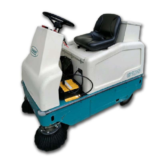
OPERATION MACHINE COMPONENTS A. Instrument panel B. Steering wheel C. Operator pedals D. Operator seat E. Batteries F. Hopper G. Instant Access filter H. Brush door 6100E 330250 (9- -04) -
Page 9: Symbol Definitions
OPERATION SYMBOL DEFINITIONS These symbols identify controls, displays, and features on the machine: Operating lights Hazard light Main brush down Start Main brush up Vacuum Fan Circuit breaker #1 Main brush on Circuit breaker #2 Filter shaker Circuit breaker #3 Side brush down and on Circuit breaker #4 Side brush up and off... -
Page 10: Controls And Instruments
OPERATION CONTROLS AND INSTRUMENTS A. Main brush, vacuum fan and filter shaker switch B. Operating/Hazard light switch (option) C. Hourmeter D. Power kill switch E. On/Off key switch F. Main brush lever G. Battery discharge indicator H. Horn button Directional pedal J. -
Page 11: Operation Of Controls
OPERATION OPERATION OF CONTROLS DIRECTIONAL PEDAL The directional pedal controls the direction of travel and the propelling speed of the machine. Change the speed of the machine with the pressure of your foot on the pedal; the harder you press the faster the machine travels. Use the brake pedal to stop the machine. -
Page 12: Brake Pedal
OPERATION BRAKE PEDAL The brake pedal stops the machine. Stop: Remove your foot from the directional pedal and let it return to the Neutral position. Step on the brake pedal to prevent the machine from rolling. NOTE: Machine may roll a slight distance when turned off. -
Page 13: Main Brush Lever
OPERATION MAIN BRUSH LEVER The main brush lever controls the position of the main brush. Main brush down: Pull the lever to the right and back into the Main brush down position. Main brush up: Push the lever up and to the left into the Main brush up position. -
Page 14: Battery Discharge Indicator
OPERATION BATTERY DISCHARGE INDICATOR The battery discharge indicator shows the charge level of the batteries. It displays the charge level when the machine is operating. When the batteries are fully charged, the indicator on the far right is lit. As the batteries discharge, the indicator will move along the display to the left. -
Page 15: On-Off Key Switch
OPERATION ON-OFF KEY SWITCH The on-off key switch controls machine power with a key. On: Turn the key clockwise all the way. Off: Turn the key counterclockwise. NOTE: The machine will not travel unless the operator is sitting in the operator’s seat. HORN BUTTON The horn button operates the horn. -
Page 16: Operating Lights Switch (Option)
OPERATION OPERATING LIGHTS SWITCH (OPTION) The operating lights switch powers on and off the headlights and taillights option. On: Press the top of the operating lights switch. Off: Press the switch to the middle position. OPERATING/HAZARD LIGHTS SWITCH (OPTION) The operating/hazard lights switch powers on and off the headlights and taillights option and the hazard light option. -
Page 17: Fuses
OPERATION FUSES Fuses are one-time protection devices designed to stop the flow of current in the event of a circuit overload. Never substitute higher value fuses than specified. The fuse is located in the control box. Fuse Rating Circuit Protected FU-1 40 A Main... -
Page 18: Operator Seat
OPERATION OPERATOR SEAT The operator seat is a stationary fixed back style. ADJUSTABLE OPERATOR SEAT (OPTION) This operator seat is a fixed back style with a forward-backward adjustment. Adjust: Pull the lever in, slide the seat backward or forward to the desired position, and release the lever to lock the seat in place. -
Page 19: Hopper
OPERATION HOPPER The hopper is located in the rear of the machine under the battery compartment. The hopper rolls in and out of position and rests in grooves that hold the hopper in place. The hopper is held in operating position with a retaining clip. -
Page 20: How The Machine Works
OPERATION HOW THE MACHINE WORKS The steering wheel controls the direction of machine travel. The directional pedal controls the speed and forward/reverse direction. The brake pedal slows and stops the machine. The side brush sweeps debris into the path of the main sweeping brush. -
Page 21: Starting The Machine
OPERATION STARTING THE MACHINE 1. Sit in the operator’s seat and engage the brakes with the directional pedal in neutral. FOR SAFETY: When starting machine, keep foot on brake and directional pedal in neutral. 2. Turn the machine power on. 3. -
Page 22: Operation On Inclines
OPERATION OPERATION ON INCLINES Drive the machine slowly on inclines. Use the brake pedal to control machine speed when descending inclines. The maximum rated incline is 8_ with a full hopper and 10_ with an empty hopper. FOR SAFETY: When using machine, go slowly on inclines and slippery surfaces. -
Page 23: Sweeping And Brush Information
OPERATION SWEEPING AND BRUSH INFORMATION Pick up oversized debris before sweeping. Flatten or remove bulky cartons from aisles before sweeping. Pick up pieces of wire, twine, string, etc., which could become entangled in the brush or brush plugs. Plan the sweeping in advance. Try to arrange long runs with minimum stopping and starting. - Page 24 OPERATION Side Brush (2 Row) -- A good general purpose brush for sweeping of light to medium debris in both indoor and outdoor applications. This brush is recommended when bristles may get wet. Side Brush (3 Row) -- Improved sweeping performance of fine materials on smooth indoor surfaces.
-
Page 25: Sweeping
OPERATION SWEEPING 1. Push the Main brush, vacuum fan and filter shaker switch to the Main brush, vacuum fan on position. 2. Lower the main brush with the main brush lever. 3. Lower and start the side brush with the side brush lever. - Page 26 OPERATION 4. Begin sweeping. 5. Press down on the large debris trap pedal when sweeping large debris. 6. Release the pedal, and the flap will lower over the debris. 7. The flap will trap large debris back into the hopper. 6100E 330250 (8- -98)
-
Page 27: Stop Sweeping
OPERATION STOP SWEEPING 1. Raise and stop the side brush with the side brush lever. 2. Raise the main brush with the main brush lever. 3. Press the main brush, vacuum fan and filter shaker switch to the middle off position. 4. -
Page 28: Stopping The Machine
OPERATION STOPPING THE MACHINE 1. Stop sweeping. See the STOP SWEEPING section of the manual. 2. Take your foot off the directional pedal. Step on the brake pedal. NOTE: The machine may coast for a short distance when your foot is removed from the directional pedal. -
Page 29: Emptying The Hopper
OPERATION EMPTYING THE HOPPER 1. Stop sweeping. See the STOP SWEEPING section of the manual. WARNING: Brush throws debris. Stop motor before lifting hopper. 2. Drive the machine to the debris site or debris container. 3. Stop the machine. See the STOP THE MACHINE section of the manual. -
Page 30: Post-Operation Checklist
OPERATION POST-OPERATION CHECKLIST Check this list of items after you have finished sweeping: - Check the hydraulic fluid level. (if applicable) - Check the battery fluid and charge level. - Check the skirts and seals for damage and wear. - Check the condition of the sweeping brushes. -
Page 31: Options
OPERATION OPTIONS VACUUM WAND The vacuum wand uses a separate vacuum system to pick-up any debris that is out of reach of the machine. 1. Turn machine on. NOTE: The main brush, vacuum fan and filter shaker switch does not have to be turned on for the vacuum wand system to operate. - Page 32 OPERATION 3. Wand On: Raise the vacuum wand from the storage position. The vacuum will turn on automatically. 4. Wand Off: Return the vacuum wand back to storage position and the vacuum will turn off. 5. Turn the cam knob clockwise to secure vacuum wand rod handle.
-
Page 33: Quick Mop
OPERATION QUICK MOP The QuickMop is a front end sweeping attachment that widens the machine’s sweeping path. 1. Drive the machine close to QuickMop attachment. 2. Set the machine parking brake and turn the machine power off. FOR SAFETY: Before leaving or servicing machine, stop on level surface, set parking brake, turn off machine, and remove key. - Page 34 OPERATION 5. On newer machines, fasten the latches on the front of the mounting bracket. Release the parking brake and drive to the designated area to be swept. 6. Pull the release lever to raise or lower each side of the QuickMop. 7.
-
Page 35: Rollout Battery
OPERATION ROLLOUT BATTERY The rollout battery allows the operator a quick and easy way to remove and replace the batteries from the machine. 1. Drive the machine to a flat, dry surface. 2. Turn the machine off and set the parking brake. - Page 36 OPERATION 6. Lock the battery cart to the machine by pulling the battery cart locks towards the outside of the battery cart. 7. Set the battery cart floor lock by stepping down on the left side of the floor lock. 8.
- Page 37 OPERATION 10. Raise the machine’s battery stop arm all the way to the horizontal position. 11. Raise the cart’s battery stop bar by pushing down on the handle. 12. Grab the battery case slot and pull the battery case onto the battery cart. 13.
- Page 38 OPERATION 14. Release the battery cart from the machine by pushing the battery cart locks towards the inside of the battery cart. 15. Release the battery cart floor lock. To release the floor lock, step down on the right side of the floor lock. 16.
-
Page 39: Machine Troubleshooting
Hopper dust filter clogged Shake and/or clean or replace dust filter Vacuum hose damaged Replace vacuum hose Vacuum fan failure Contact Tennant service personnel Poor sweeping performance Brush bristles worn Replace brushes Main and side brushes not Adjust main and side brushes... -
Page 40: Maintenance
MAINTENANCE MAINTENANCE MAINTENANCE CHART No. of Lubricant/ Service Fluid Interval Description Procedure Points Daily Brush compartment skirts Check for damage, wear, and adjustment Main brush Check for damage or wear Side brush(es) Check for damage or wear 1 (2) Check brush pattern 1 (2) Hopper dust filter Shake... - Page 41 ..Distilled water ..SAE 30 Engine oil . . . Special lubricant, Lubriplate EMB grease (TENNANT part no. 01433--1) NOTE: More frequent intervals may be required in extremely dusty conditions. 6100E 330250 (9- -02)
-
Page 42: Lubrication
MAINTENANCE LUBRICATION PROPELLING SYSTEM (For machines below serial number 002363) The front wheel chain drive/support propels the front wheel to drive the machine. Check the propelling system and chain tension every 100 hours. Proper chain tension is 3 mm (.125 in) from slight tension applied at the midpoint of the longest span. -
Page 43: Steering Castor Pivot Bearing
01433--1) every 100 hours. STEERING CASTER PIVOT BEARING (For machines serial number 002363 and above) The steering caster bearing is located on the floorplate. Lubricate with Lubriplate EMB grease (TENNANT part no. 01433--1) every 100 hours. 6100E 330250 (9- -02) -
Page 44: Batteries
MAINTENANCE BATTERIES The batteries are unique in that they hold their power for long periods of time. The lifetime of the batteries is limited by the number of charges the batteries receive. To get the most life from the batteries, charge them when the last battery discharge indicator segment flashes (20% charge left). -
Page 45: Charging The Batteries
MAINTENANCE NOTE: Do not take readings immediately after adding distilled water. If the water and acid are not thoroughly mixed, the readings may not be accurate. Check the hydrometer readings against the following chart to determine the remaining battery charge level: Spec. - Page 46 NOTE: If the red “ABNORMAL CYCLE” lamp lights when the batteries are plugged into the TENNANT charger, this indicates that something is wrong with the battery. The charger can not charge the battery when this happens. 6100E 330250 (9- -02)
- Page 47 MAINTENANCE 8. The Tennant charger will start automatically. When the batteries are fully charged, the Tennant charger will automatically turn off. NOTE: Use a charger with the proper rating for the batteries to prevent damage to the batteries or reduce the battery life.
-
Page 48: Electric Motors
MAINTENANCE ELECTRIC MOTORS The carbon brushes on the propelling and accessories motors should be inspected after every 800 hours of machine operation. BELTS AND CHAINS VACUUM FAN BELT Check the vacuum fan belt tension and wear after every 200 hours of operation. The correct tension is when the belt deflects 12.7 mm (0.50 in) from a force of 15 kg (30 to 40 lb) at belt midpoint. -
Page 49: Steering Gear Chain (For Machines Below Serial Number 002363)
MAINTENANCE STEERING GEAR CHAIN (For machines below serial number 002363) The steering chain turns the front wheel as the steering wheel is turned. Lubricate the steering chain with SAE 30--weight engine oil every 200 hours of operation. STEERING GEAR CHAIN (For machines serial number 002363 and above) The steering gear chain is located directly above the front tire. -
Page 50: Debris Hopper
MAINTENANCE DEBRIS HOPPER INSTANT ACCESS HOPPER FILTER The Instant Access hopper filter filters the air pulled up from the hopper. The dust filter is equipped with a shaker to remove the accumulated dust particles. The dust filter shaker is operated by the main brush, vacuum and filter shaker switch. -
Page 51: Removing Instant Access Filter
MAINTENANCE REMOVING INSTANT ACCESS FILTER 1. Stop the machine, set the parking brake and turn the machine power off. FOR SAFETY: Before leaving or servicing machine, stop on level surface, set parking brake, turn off machine, and remove key. 2. Turn the hopper retaining clip and remove hopper. - Page 52 MAINTENANCE 5. Unplug the electrical harness connection from the VCS system filter shaker. NOTE: Carefully pull the wires apart from the bodies of the plugs. Do not unplug the connections from the shaking mechanism. Do not pull on the wires. Damage could occur to the wires or the shaking mechanism.
- Page 53 MAINTENANCE 9. Replace the VCS system filter shaker. Use care to insert the shaking pin into the filter comb correctly. 10. Place the edges of the shaker firmly between the filter and the filter seal. NOTE: When installed properly, the shaker plate cannot move in either front- -to- -back or side- -to- -side directions.
- Page 54 MAINTENANCE 12. Check the shaker solenoid gap with the end of the shipping tab. The gap should be the same width as the tab. If it is not, loosen the mounting screws, adjust the gap by repositioning the shaker solenoid, then retighten the screws.
- Page 55 MAINTENANCE 15. Latch the two dust filter securing latches above the hopper storage area. 16. Check all of the hopper seals for wear. 17. Replace the hopper. 6100E 330250 (9- -02)
-
Page 56: Brushes
MAINTENANCE BRUSHES MAIN BRUSH The main brush is cylindrical and spans the width of the machine, sweeping debris into the hopper. Check the brush daily for wear or damage. Remove any string or wire tangled on the main brush, main brush drive hub, or main brush idler hub. -
Page 57: Checking And Adjusting Main Brush Pattern
MAINTENANCE 4. Grasp the main brush; pull it off the brush drive plug and out of the main brush compartment. 5. Put the new or rotated end-for-end main brush on the floor next to the access door. 6. Slide the main brush onto the drive plug. Rotate the brush until it engages the drive plug, and push it all the way onto the plug. - Page 58 MAINTENANCE 6. Observe the width of the brush pattern. The proper brush pattern width is 50 to 75 mm (2 to 3 in). The brush taper is factory set and should not need adjustment unless parts of the brush system have been replaced. 00582 If the main brush pattern is tapered, more than 15 mm (0.5 in) on one end than the...
-
Page 59: Side Brush
MAINTENANCE SIDE BRUSH The side brush sweeps debris along edges into the path of the main brush. Check the brush daily for wear or damage. Remove any string or wire found tangled on the side brush or side brush drive hub. Check the side brush pattern daily. -
Page 60: Replacing Side Brush
MAINTENANCE REPLACING SIDE BRUSH 1. Stop the machine, set the parking brake and turn the machine power off. FOR SAFETY: Before leaving or servicing machine, stop on level surface, set parking brake, turn off machine, and remove key. 2. Remove the side brush retaining pin from the side brush drive shaft by pulling the pin keeper off over the end of the pin. -
Page 61: Skirts And Seals
MAINTENANCE SKIRTS AND SEALS REAR SKIRT The two rear skirts are located on the bottom rear of the main brush compartment. The vertical skirt should clear the floor up to 5 mm (0.25 in). The recirculation skirt requires no adjustment. Check the skirts for wear or damage and adjustment daily. -
Page 62: Large Debris Trap Skirt
MAINTENANCE LARGE DEBRIS TRAP SKIRT The large debris trap skirt is located along the front of the main brush. This skirt is raised and lowered by the large debris trap pedal, allowing larger debris to be trapped and swept up into the hopper. -
Page 63: Brakes And Tires
MAINTENANCE BRAKES AND TIRES BRAKES (For machines below serial number 002363) The mechanical brake is located on the front wheel. The brake is operated by the brake foot pedal. Check the brake adjustment after every 200 hours of operation. If the brake does not respond well to pressure on the brake pedal, you may need to adjust the brake. -
Page 64: Brakes (For Machines Serial Number 002363 And Above)
MAINTENANCE BRAKES (For machines serial number 002363 and above) The mechanical brake is located on the front wheel. The brake is operated by the brake pedal. Check the brake adjustment after every 200 hours of operation. If the brake does not respond well to pressure on the brake pedal, you may need to adjust the brake. -
Page 65: Tires
MAINTENANCE TIRES The machine has three tires: one in front, and two in the rear of the machine. All three tires are solid rubber. Check the tires for damage and wear after every 100 hours of operation. 6100E 330250 (9- -02) -
Page 66: Pushing, Towing, And Transporting The Machine
MAINTENANCE PUSHING, TOWING, AND TRANSPORTING THE MACHINE PUSHING OR TOWING THE MACHINE If the machine becomes disabled, it can be pushed or towed from the front or rear, but it is easier and more stable to tow from the front end. (For machines below serial number 002363) Unplug the drive motor from the electrical harness before attempting to push the machine. - Page 67 MAINTENANCE 3. To winch the machine onto the truck or trailer, attach the winching chains to the front tie down located in the front of the machine frame. 4. (For machines below serial number 002363) Unplug the drive motor from the electrical harness before winching the machine onto the truck or trailer.
- Page 68 MAINTENANCE 6. Set the parking brake and block the machine tires. Tie down the machine to the truck or trailer before transporting. The front tie-down locations are the holes in the front of the machine frame. The rear tie-down locations are the holes in the sides of the machine frame near the rear bumper.
-
Page 69: Machine Jacking
MAINTENANCE MACHINE JACKING Empty the hopper before jacking the machine. You can jack up the machine for service at the designated locations. Use a hoist or jack that will support the weight of the machine. Always stop the machine on a flat, level surface and block the tires before jacking up the machine. -
Page 70: Specifications
SPECIFICATIONS SPECIFICATIONS GENERAL MACHINE DIMENSIONS/CAPACITIES Item Dimension/capacity Length 1520 mm (60 in) Width 805 mm (32 in) Height 1180 mm (46 in) Track 880 mm (35 in) Wheelbase 682 mm (27 in) Main sweeping brush diameter 280 mm (11 in) Main sweeping brush length 560 mm (22 in) -
Page 71: Power Type
SPECIFICATIONS POWER TYPE Type Quantity Volts Ah Rating Weight Batteries 220 @ hr rate 177 kg (390lbs) Type Kw (hp) Electric Motor (S/N 000000--002362) Propelling .56 (.75 hp) Electric Motor (S/N 002363-- Propelling 1.0 (1.34 hp) Type Phase Charger STEERING Type Power source Emergency steering... -
Page 72: Machine Dimensions
SPECIFICATIONS 1520 mm (60 in) 805 mm (32 in) TOP VIEW 1180 mm (46 in) SIDE VIEW 352185 MACHINE DIMENSIONS 6100E 330250 (9- -02) -
Page 73: Index
INDEX Control panel Battery discharge indicator, 12 Aisle turn, 68 Hourmeter, 12 Operating lights switch, 14 Operating/hazard lights switch, 14 Controls, 8 Batteries, 42–46 Battery discharge indicator, 12 Charger specifications, 69 Brake pedal, 10 Charging, 43–46 Circuit breakers, 15 Discharge indicator, 12 Directional pedal, 9 Maintenance, 42 Fuse, 15... - Page 74 INDEX Main brush, 21, 54–57 Adjust brush taper, 56 Hopper Belt, 46 Changing dust filter, 49–51 Bristle length, 54 Cleaning dust filter, 48 Checking brush pattern, 55–57 Debris, 48–50 Door seals, 59, 60 Dust filter, 48–50 Hopper seals, 60 Emptying the hopper, 27–30 Maintenance, 54 Seals, 60 Rear skirts, 59...
- Page 75 INDEX Side brush guard, 58 Side brush lever, 13 Parking brake pedal, 10 Skirts, 28, 59–62 Pedal, Directional, 9 Large debris trap, Seals, 60 Pedals Rear, 59 Brake, 10 Specifications, 68–71 Large debris trap pedal, 10 Braking system, 69 Parking brake, 10 Chargers, 69 Post-operation checklist, 28 Electric motors, 69...
- Page 76 INDEX Tie down location, 66 Tires, 61, 63 Specifications, 69 Towing machine, 64 Transporting machine, 64 Transporting the machine, 64 Travel speed, 68 Troubleshooting, 37 Upper hopper seals, 60 Vacuum fan, Belt, 46 Vacuum fan belt, 46 Vacuum Wand Option, 29 6100E 330250 (9- -02)
Need help?
Do you have a question about the 6100 and is the answer not in the manual?
Questions and answers