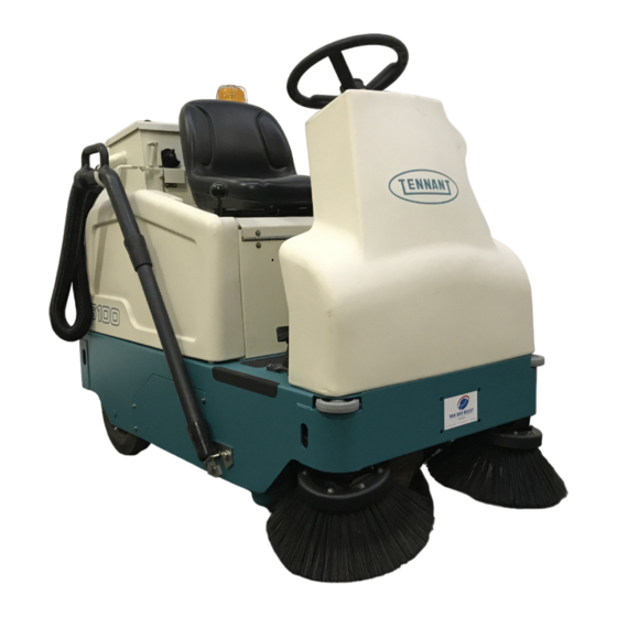
Tennant 6100 Operator's Manual
Hide thumbs
Also See for 6100:
- Operator's manual (76 pages) ,
- Instruction bulletin (7 pages) ,
- Instruction bulletin (6 pages)
Table of Contents
Advertisement
Advertisement
Table of Contents

Related Manuals for Tennant 6100


Summary of Contents for Tennant 6100
- Page 1 6100 Operator Manual 330230 Rev. 04 *330230*...
- Page 2 This manual is furnished with each new TENNANT Model 6100. It provides necessary operating and preventive maintenance instructions. Read this manual completely and understand the machine before operating or servicing it. This machine will provide excellent service. However, the best results will be obtained at minimum costs D The machine is operated with reasonable care.
-
Page 3: Table Of Contents
INDEX ........6100 330230 (12- -00) -
Page 4: Safety Precautions
FOR SAFETY: - - Use cardboard to locate leaking hydraulic fluid under pressure. 1. Do not operate machine: - - Use Tennant supplied or equivalent - - Unless trained and authorized. replacement parts. - - Unless operation manual is read and understood. - Page 5 FOR SAFETY LABEL - - LOCATED ON THE SIDE OF THE OPERATOR COMPARTMENT. FLYING DEBRIS LABEL - - LOCATED ABOVE HOPPER. EMISSIONS LABEL - - LOCATED BELOW CONTROL PANEL. 352685 6100 330230 (6- -99)
-
Page 6: Operation
Tennant representative. - Order parts and supplies directly from your authorized Tennant representative. Use the parts manual provided when ordering parts. - After the first 50 hours of operation, follow the recommended daily and hourly procedures stated in the MAINTENANCE CHART. -
Page 7: Machine Components
OPERATION MACHINE COMPONENTS A. Instrument panel B. Steering wheel C. Operator pedals D. Operator seat E. Engine F. Fuel tank G. Hopper H. Instant Accesst filter Brush door 6100 330230 (6- -99) -
Page 8: Symbol Definitions
Main brush down Hazard light Main brush up Engine Oil Pressure Circuit breaker #1 Battery charging system Circuit breaker #2 Filter shaker Circuit breaker #3 Side brush down and on Horn Side brush up and off Choke 6100 330230 (6- -99) -
Page 9: Controls And Instruments
G. Ignition switch H. Horn button Steering wheel J. Directional pedal K. Main brush lever L. Operator seat M. Circuit breaker panel N. Brake pedal O. Parking brake pedal P. Choke knob (gasoline) Q. Large debris trap pedal 6100 330230 (6- -99) -
Page 10: Operation Of Controls
Neutral position. NOTE: The machine may coast when the foot is taken off the directional pedal. Be prepared to step on the brake pedal when removing foot from directional pedal. 6100 330230 (6- -99) -
Page 11: Brake Pedal
Open: Press on the trap pedal when sweeping up larger debris. The flap in front of the main sweeping brush will open. Close: Release the pedal and the flap will close, trapping larger debris into the hopper. 6100 330230 (6- -99) -
Page 12: Main Brush Lever
ENGINE OIL PRESSURE LIGHT The engine oil pressure light comes on when the engine oil pressure falls below 40kPa (5 psi). If the light comes on, stop operating the machine. Locate the problem and have it corrected. 6100 330230 (6- -99) -
Page 13: Fuel Level Gauge
ENGINE CHOKE KNOB The engine choke knob controls the engine choke on gasoline powered machines. On: For cold starting, pull the engine choke knob out. Off: Push the engine choke knob in. 6100 330230 (6- -99) -
Page 14: Vacuum Fan/Filter Shaker Switch
Right: Turn the steering wheel to the right. HOURMETER The hourmeter records the number of hours the machine has been operated. The hourmeter displays the number of hours in tenths of an hour. Use this information to determine machine maintenance intervals. 6100 330230 (6- -99) -
Page 15: Ignition Switch
Side brush down and on position. The brush will automatically start rotating. Side brush up and off: Pull the lever back and to the right into the Side brush up and off position. 6100 330230 (6- -99) -
Page 16: Operating Lights Switch (Option)
Operating lights on: Press the top of the operating/hazard lights switch. Operating/Hazard lights on: Press the bottom of the operating/hazard lights switch. Off: Press the operating/hazard lights switch to the middle off position. 6100 330230 (6- -99) -
Page 17: Fuses
The chart lists the circuit breakers and the electrical components they protect. Circuit Breaker Rating Circuit Protected CB-1 15 A Horn / Back up alrm CB-2 15 A Filter shaker CB-3 10 A Main 6100 330230 (12- -99) -
Page 18: Operator Seat
This operator seat is a fixed back style with a forward-backward adjustment. Adjust: Pull the lever in, slide the seat backward or forward to the desired position, and release the lever to lock the seat in place. 6100 330230 (6- -99) -
Page 19: Hopper
Lift up on the hopper handle. Pull the hopper back out of the machine. Replace hopper: Push hopper back into position under hopper filter. Secure hopper in position with hopper retaining clip. 6100 330230 (6- -99) -
Page 20: How The Machine Works
Instant Accesst filter. When sweeping is finished, clean the Instant Accesst filter and empty the hopper. PRE-OPERATION CHECKLIST - Check under the machine for leaks (fuel, oil or hydraulic fluid). - Check the engine air filter. 6100 330230 (6- -99) - Page 21 - Check the fuel level gauge. - LPG powered machines: When checking the fuel gauge on the tank, check for LPG odor or frosting on hoses or components indicating an LPG leak. - Check the brakes and steering for proper operation. 6100 330230 (6- -99)
-
Page 22: Changing An Lpg Fuel Tank
NOTE: Make sure the LPG fuel tank matches the fuel system (vapor tank with vapor system). 7. Fasten the tank hold-down clamp to lock the tank in position. 6100 330230 (6- -99) - Page 23 Also make sure it matches the machine service coupling. 9. Open the tank service valve slowly and check for leaks. Close the service valve immediately if an LPG leak is found, and tell the appropriate personnel. 6100 330230 (6- -99)
-
Page 24: Starting The Machine
FOR SAFETY: When starting machine, keep foot on brake and directional pedal in neutral. 3. Gasoline powered machines: Pull out the choke knob when the engine is cold. Push in the choke knob after the engine is running smoothly. 6100 330230 (6- -99) - Page 25 Severe respiratory damage or asphyxiation can result. Provide adequate ventilation. Consult with your regulatory authorities for exposure limits. Keep engine properly tuned. 6. Release the machine parking brake. 7. Drive the machine to the area to be cleaned. 6100 330230 (6- -99)
-
Page 26: Operation On Inclines
The maximum rated incline is 8_ with a full hopper and 10_ with an empty hopper. FOR SAFETY: When using machine, go slowly on inclines and slippery surfaces. 6100 330230 (6- -99) -
Page 27: Sweeping And Brush Information
When cleaning carpet, check brush and perma filter panel regularly for carpet debris. Sand wedge main brush -- A fine brush that handles large quantities of dust and sand with ease. 6100 330230 (12- -01) -
Page 28: Sweeping
Stiff Side Brush -- A longer life, general purpose brush that is recommended for rough surfaces. SWEEPING 1. Press the top of the vacuum fan/filter shaker switch to the vacuum fan damper open position. 2. Lower the main brush with the main brush lever. 6100 330230 (9- -02) - Page 29 5. Press down on the large debris trap pedal when sweeping large debris. 6. Release the pedal, and the flap will lower over the debris. 7. The flap will trap large debris back into the hopper. 6100 330230 (6- -99)
-
Page 30: Stop Sweeping
3. Close the vacuum fan damper by pressing the vacuum fan/filter shaker switch to the middle off position. 4. Activate the filter shaker by pressing down and holding the bottom of the vacuum fan/filter shaker switch for eight to ten seconds. 6100 330230 (6- -99) -
Page 31: Stopping The Machine
NOTE: The machine may coast for a short distance when your foot is removed from the directional pedal. Use the brake pedal to stop the machine. 3. Set the machine parking brake. 6100 330230 (6- -99) - Page 32 Remove the switch key. FOR SAFETY: Before leaving or servicing machine, stop on level surface, set parking brake, turn off machine, and remove key. 5. LPG powered machines: Close the LPG tank’s vapor service valve. 6100 330230 (6- -99)
-
Page 33: Emptying The Hopper
7. Roll the hopper to debris container. Empty the hopper. FOR SAFETY: Use care when emptying hopper. Hopper can hold up to 200lbs. Lifting heavy material improperly can result in back strain or other personal injury. 6100 330230 (6- -99) -
Page 34: Post-Operation Checklist
LPG tank vapor service valve is closed. - Check for fuel odor that indicates a fuel leak. - Check under the machine for leak spots (fuel, oil). - Check the service records to determine maintenance requirements. 6100 330230 (6- -99) -
Page 35: Options
4. On older machines, hand tighten the threaded connector knob on the front of the mounting bracket. Release the parking brake and drive to the designated area to be swept. 6100 330230 (12- -99) - Page 36 7. Turn the vacuum and brushes on, lower brushes and begin sweeping. 8. Remove and refasten the QuickMopt head covers with the easy to remove snaps. Remove the head covers to rotate, shake and clean at regular intervals. 6100 330230 (12- -99)
-
Page 37: Machine Troubleshooting
Hopper dust filter clogged Shake and/or clean or replace dust filter Machine will not start Engine oil level low Check and fill Fuel tank valve closed Open valve -- LPG tank valve or valve below gasoline tank 6100 330230 (6- -99) -
Page 38: Maintenance
50 Hours Engine oil Change Engine air filter Replace Vacuum fan belt Check tension and wear Main brush Rotate end-for-end Check brush pattern QuickMoptbroom (Option) Rotate or wash sweep heads Fuel lines Check for damage and wear 6100 330230 (12- -99) - Page 39 TENNANT or approved hydraulic fluid . . . Special lubricant, Lubriplate EMB grease (TENNANT part no. 01433--1 NOTE: More frequent intervals may be required in extremely dusty conditions. NOTE: Also check procedures indicated (H) after the first 50 hours of operation.
-
Page 40: Lubrication
Proper chain tension is 3 mm (.125 in) from slight tension applied at the midpoint of the longest span. Lubricate the propelling chain with SAE 10W30 weight engine oil after every 100 hours of operation. 6100 330230 (12- -99) -
Page 41: Steering Gear Chain
SAE 10W30--weight engine oil every 200 hours of operation. STEERING CASTOR PIVOT BEARING The steering castor bearing is located under the front wheel housing. Lubricate the bearing with Lubriplate EMB grease (TENNANT part no. 01433--1) every 100 hours. 6100 330230 (12- -99) -
Page 42: Hydraulics
Replace the filter element after every 800 hours of operation. The reservoir has a built-in strainer outlet that filters hydraulic fluid before it enters the system. Replace the strainer after every 800 hours of operation. 6100 330230 (12- -99) -
Page 43: Hydraulic Fluid
The quality and condition of the hydraulic fluid play a very important role in how well the machine operates. Tennant’s hydraulic fluid is specially selected to meet the needs of Tennant machines. Tennant’s hydraulic fluids provide a longer life for the hydraulic components. There are two fluids... -
Page 44: Engine
Clean the housing sealing surfaces. Inspect the inner air filter element for damage. The slightest rupture requires replacement of the element. Inspect the seals on the ends of the element. They should be flexible and undamaged. 6100 330230 (12- -99) -
Page 45: Fuel Screen
Bleed the fuel system after replacement of any fuel lines. When the fuel lines are not installed, plug both ends with clean cloth or paper to prevent dirt from entering the lines. 6100 330230 (12- -99) -
Page 46: Carburetor
The battery is located in the engine compartment. After the first 50 hours of operation, and after every 800 hours after that, clean and tighten the battery connections. FOR SAFETY: When servicing machine, avoid contact with battery acid. 6100 330230 (12- -99) -
Page 47: Belts And Chains
Check the main brush belt for wear after every 100 hours of operation. The idler keeps tension on the belt. The correct static tension on the main belt is 7.63 kg (16.95 lb.) with 6.14 kg (13.65 lb) of force from the idler pulley. 6100 330230 (12- -99) -
Page 48: Hydraulic Pump Belt
Check the belt for tension and wear every 100 hours of operation. JACKSHAFT BELT The jackshaft belt turns the jackshaft that drives the main brush and vacuum fan belts. Check the belt for tension and wear every 100 hours of operation. 6100 330230 (12- -99) -
Page 49: Propelling System
A static drag chain prevents the buildup of static electricity in the machine. The chain is attached to the machine by a rear main brush skirt retaining bolt. Make sure the chain is touching the floor at all times. 6100 330230 (12- -99) -
Page 50: Debris Hopper
Rinse the dust filter until it is clean. Air dry the wet dust filter; do not use compressed air to dry a wet filter. NOTE: Be sure the dust filter is completely dry before reinstalling it in the machine. 6100 330230 (12- -99) -
Page 51: Removing Instant Accesst Filter
2. Turn the hopper retaining clip and remove hopper. 3. Unlatch the two dust filter securing latches above the hopper storage area. 4. Lower the hopper filter down to access the VCSt filter shaker. 6100 330230 (12- -99) - Page 52 Damage could occur to the wires or the shaking mechanism. 6. Lift the Instant Accesst filter from filter tray. 7. Lift the VCSt system filter shaker off of the filter. 8. Clean or discard the Instant Accesst filter as required. 6100 330230 (12- -99)
- Page 53 -to- -side directions. If the shaker is loose, it will not function properly. 11. The filter shaker should lay flat against the filter. Check to make sure the comb tab is not caught below the filter shaker plate. 6100 330230 (12- -99)
- Page 54 If it is not, loosen the mounting screws, adjust the gap by repositioning the shaker solenoid, then retighten the screws. 13. Return the filter to the hopper filter weldment. 14. Reconnect the electrical harness to the shaker mechanism harness. 6100 330230 (12- -99)
-
Page 55: Thermo Sentryt
The damper will cut off air flow and help extinguish the fire. If this occurs, drive the machine to a safe location, remove the hopper and eliminate the source of heat. 6100 330230 (12- -99) -
Page 56: Brushes
2. Open the left side main brush access door. 3. Loosen the idler arm mounting knob and three other side skirt mounting knobs. Remove the brush idler arm assembly. 6100 330230 (12- -99) -
Page 57: Checking And Adjusting Main Brush Pattern
NOTE: If chalk or other material is not available, allow the brushes to spin on the floor for two minutes. A polish mark will remain on the floor. 4. Raise the main brush. 5. Drive the machine off the test area. 6100 330230 (12- -99) - Page 58 B. Allow the brush to operate and float into position for approximately 30 seconds. C. Tighten the adjustment bolt and idler arm securing knob. D. Check the main brush pattern and readjust as necessary. 6100 330230 (12- -99)
-
Page 59: Side Brush
50 mm (2 in) in length. You may need to replace the side brush sooner if you are sweeping light litter or use a brush with shorter bristles if you are sweeping heavy debris. 6100 330230 (12- -99) -
Page 60: Replacing Side Brush
7. Adjust the side brush pattern with the side brush pulley mount bracket. SIDE BRUSH GUARD Check the side brush guard after every 200 hours of operation. Replace the brush guard after it begins to show serious wear. 6100 330230 (12- -00) -
Page 61: Skirts And Seals
Check the skirts for wear or damage and adjustment daily. NOTE: The recirculation skirt must be folded in between the brush and the machine frame before the brush door is mounted for the machine to work properly. 6100 330230 (12- -99) -
Page 62: Side Skirts
Check the seals for wear or damage after every 100 hours of operation. The upper hopper seal is located above the hopper on the bottom of the filter weldment. Check the seal for wear or damage after every 100 hours of operation. 6100 330230 (12- -99) -
Page 63: Brakes And Tires
Remove the cotter key from the brake extension arm, and position the extension arm in the next adjustment hole in the brake link. Insert the cotter key back into the brake extension arm, and check the brake for proper operation. 6100 330230 (12- -99) - Page 64 MAINTENANCE TIRES The tires on the machine are solid. Check the tires after every 100 hours of operation for damage. 6100 330230 (12- -99)
-
Page 65: Pushing, Towing, And Transporting The Machine
FOR SAFETY: When loading machine onto truck or trailer, use winch. Do not drive the machine onto the truck or trailer unless the loading surface is horizontal AND is 380 mm (15 in) or less from the ground. 6100 330230 (12- -00) - Page 66 FOR SAFETY: When unloading machine off truck or trailer, use winch. Do not drive the machine off the truck or trailer unless the loading surface is horizontal AND 380 mm (15 in) or less from the ground. 6100 330230 (12- -00)
-
Page 67: Machine Jacking
Block machine up with jack stands. STORING MACHINE Before storing the machine for an extended time, the machine needs to be serviced to lessen the chance of rust, sludge, and other undesirable deposits from forming. 6100 330230 (12- -00) -
Page 68: Specifications
4.8 km/h (3 mph) Minimum aisle turn 1830 mm (72 in) Minimum turning radius 1725 mm (68 in) Maximum rated incline with empty hopper 10_ / 17.5% Maximum rated incline with full hopper 8_ / 14% 6100 330230 (9- -02) -
Page 69: Power Type
Manual HYDRAULIC SYSTEM System Capacity Fluid Type Hydraulic reservoir 7.58 L (2 gal) TENNANT part no. 65869--above 7° C (45° F) Hydraulic total 9.48 L (2.5 gal) BRAKING SYSTEM Type Operation Service brakes Mechanical disc brake (1), one front wheel, cable... -
Page 70: Machine Dimensions
SPECIFICATIONS 1524 mm (60 in) 813 mm (32 in) TOP VIEW 1270 mm (50 in) SIDE VIEW FRONT VIEW 352185 MACHINE DIMENSIONS 6100 330230 (12- -99) -
Page 71: Index
Side brush lever, 13 Button, Horn, 13 Electric motors, 67 Electrical Capacities, 66 Circuit breakers, 15 Carburetor, 44 Fuse, 15 Chains, 45 On-off key switch, 13 Propelling, 38, 47 Static drag, 47 Steering gear, 39, 47 6100 330230 (12- -00) - Page 72 Checking brush pattern, 55–57 Hydraulic system, 67 Door seals, 60 Hydraulics, 40–44 Hopper seals, 60 Fluid, 41–43 Maintenance, 54 Fluid filter, 40 Rear skirts, 59 Fluid level, 40 Replacing, 54–56 Hoses, 41 Sand wedge, 25 Reservoir, 40 6100 330230 (12- -00)
- Page 73 Propelling system, 38, 47 Machine performance, 66 Pushing machine, 63 Power type, 67 Pushing or towing the machine, 63 Steering, 67 Tires, 67 Pushing, towing, and transporting machine, 63 Starting the machine, 22 Static drag chain, 47 6100 330230 (12- -00)
- Page 74 Tires, 61, 62 Specifications, 67 Towing machine, 63 Transporting machine, 63 Transporting the machine, 63 Travel speed, 66 Troubleshooting, 35 Upper hopper seals, 60 Vacuum fan, Belt, 45 Vacuum fan belt, 45 Vacuum Fan/Filter shaker switch, 12 6100 330230 (12- -00)
Need help?
Do you have a question about the 6100 and is the answer not in the manual?
Questions and answers