Tennant 6200 Operator's Manual
Hide thumbs
Also See for 6200:
- Operator's manual (80 pages) ,
- Instruction bulletin (7 pages) ,
- Instruction bulletin (3 pages)

Related Manuals for Tennant 6200


Summary of Contents for Tennant 6200
- Page 1 6200 (Electric) Sweeper Operator Manual North America / International 330410 Rev. 11 (2-2010) *330410* www.tennantco.com Home Find... Go To..
- Page 2 Phone: (800) 553--8033 or (763) 513--2850 www.tennantco.com Quick Mop, VCS, Instant Access filter, and Thermo Sentry are US registered and unregistered trademarks of Tennant Company. Specifications and parts are subject to change without notice. Original instructions. Copyright E 1999- -2003, 2005- -2008, 2010 TENNANT, Printed in U.S.A.
-
Page 3: Table Of Contents
CONTENTS CONTENTS Page Page SAFETY PRECAUTIONS ....MAINTENANCE ......OPERATION . - Page 4 CONTENTS Page SPECIFICATIONS ..... . . GENERAL MACHINE DIMENSIONS/CAPACITIES ..GENERAL MACHINE PERFORMANCE POWER TYPE .
-
Page 5: Safety Precautions
- - Avoid contact with battery acid. - - In flammable or explosive areas unless - - Use Tennant supplied or equivalent designed for use in those areas. replacement parts. - - In areas with possible falling objects unless equipped with overhead guard. - Page 6 SAFETY PRECAUTIONS The following safety labels are mounted on the machine in the locations indicated. If these or any labels become damaged or illegible, install a new label in its place. HOPPER SUPPORT LABEL - - LOCATED ON LEFT SIDE HOPPER LIFT ARM AND BOTH SIDES OF THE HOPPER COMPARTMENT FOR SAFETY LABEL - - LOCATED ON THE SIDE OF THE OPERATOR COMPARTMENT.
-
Page 7: Operation
Tennant representative. - Order parts and supplies directly from your authorized Tennant representative. Use the parts manual provided when ordering parts. - After operation, follow the recommended daily and hourly procedures stated in the MAINTENANCE CHART. -
Page 8: Machine Components
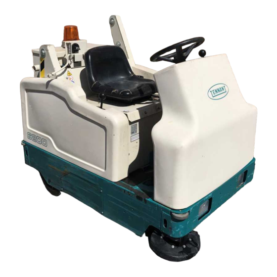
OPERATION MACHINE COMPONENTS A. Operator seat B. Steering wheel C. Instrument panel D. Side brush(es) E. Control pedals F. Hopper G. Hopper filter 6200E 330410 (6- -99) Home Find... Go To.. -
Page 9: Symbol Definitions
OPERATION SYMBOL DEFINITIONS These symbols identify controls, displays, and features on the machine: Operating lights Hazard light Main brush down Start Main brush up Vacuum Fan Circuit breaker #1 Filter shaker Circuit breaker #2 Horn Circuit breaker #3 Side brush down and on Circuit breaker #4 Side brush up and off Circuit breaker #5... -
Page 10: Controls And Instruments
OPERATION CONTROLS AND INSTRUMENTS A. Side brush(es) lever B. Power kill switch (option) C. Horn D. Battery discharge indicator E. Hourmeter F. Steering wheel G. Main brush lever H. Directional pedal Brake pedal J. Parking brake pedal (For machines below serial number 003468) K. -
Page 11: Operation Of Controls
OPERATION OPERATION OF CONTROLS DIRECTIONAL PEDAL The directional pedal controls the direction of travel and the propelling speed of the machine. Change the speed of the machine with the pressure of your foot on the pedal; the harder you press the faster the machine travels. Use the brake pedal to stop the machine. -
Page 12: Brake Pedal
OPERATION BRAKE PEDAL The brake pedal stops the machine. Stop: Remove your foot from the directional pedal and let it return to the Neutral position. Step on the brake pedal to prevent the machine from rolling. NOTE: Machine may roll a slight distance when turned off. -
Page 13: Main Brush Lever
OPERATION MAIN BRUSH LEVER The main brush lever controls the position and the power of the main brush. Main brush down and on: Pull the lever to the right and back into the Main brush down and on position. The brush will automatically start rotating. -
Page 14: Battery Discharge Indicator
OPERATION BATTERY DISCHARGE INDICATOR The battery discharge indicator shows the charge level of the batteries. It displays the charge level when the machine is operating. When the batteries are fully charged, the indicator on the far right is lit. As the batteries discharge, the indicator will move along the display to the left. -
Page 15: On--Off Key Switch
OPERATION ON- -OFF KEY SWITCH The on- -off key switch controls machine power with a key. FOR SAFETY: When starting machine, keep foot on brake and directional pedal in neutral. On: Turn the key all the way clockwise. Off: Turn the key counterclockwise. NOTE: The machine will not travel unless the operator is sitting in the operator’s seat. -
Page 16: Operating Lights Switch (Option)
OPERATION OPERATING LIGHTS SWITCH (OPTION) The operating lights switch powers on and off the headlights and taillights option. On: Press the top of the operating lights switch. Off: Press the switch to the middle position. OPERATING/HAZARD LIGHTS SWITCH (OPTION) The operating/hazard lights switch powers on and off the headlights and taillights option and the hazard light option. -
Page 17: Hopper Switch
OPERATION HOPPER SWITCH The hopper switch raises and lowers the hopper. Raise hopper: Press and hold the top of the switch until the hopper is in the desired raised position. Hold: Release the hopper switch into the middle position. Lower hopper: Press and hold the bottom of the switch until the hopper is in the desired lowered position. -
Page 18: Fuses
OPERATION FUSES Fuses are one-time protection devices designed to stop the flow of current in the event of a circuit overload. Never substitute higher value fuses than specified. The fuse is located behind the circuit breaker panel. Fuse Rating Circuit Protected FU-1 80 A Main... -
Page 19: Operator Seat
OPERATION OPERATOR SEAT The operator seat is a fixed back style. NOTE: The operator seat has a safety switch that stops the machine from propelling unless the operator is sitting in the operator’s seat. ADJUSTABLE OPERATOR SEAT (OPTION) The adjustable operator seat is a fixed back style with a foward--backward adjustment. -
Page 20: Hopper Support Bar
OPERATION The weight adjustment knob controls the firmness of the operator’s seat. Increase firmness: Turn the weight adjustment knob clockwise. Decrease firmness: Turn the weight adjustment knob counterclockwise. Use the gauge next to the weight adjustment knob to help determine proper seat firmness for the operator. -
Page 21: How The Machine Works
OPERATION HOW THE MACHINE WORKS The steering wheel controls the direction of machine travel. The directional pedal controls the speed and forward/reverse direction. The brake pedal slows and stops the machine. The side brush sweeps debris into the path of the main sweeping brush. -
Page 22: Starting The Machine
OPERATION STARTING THE MACHINE 1. Sit in the operator’s seat and engage the brakes with the directional pedal in neutral. FOR SAFETY: When starting machine, keep foot on brake and directional pedal in neutral. 2. Turn the machine power on. 3. -
Page 23: Sweeping And Brush Information
OPERATION SWEEPING AND BRUSH INFORMATION Pick up oversized debris before sweeping. Flatten or remove bulky cartons from aisles before sweeping. Pick up pieces of wire, twine, string, etc., which could become entangled in the brush or brush plugs. Plan the sweeping in advance. Try to arrange long runs with minimum stopping and starting. -
Page 24: Home Find... Go To
OPERATION Side Brush (2 Row) -- A good general purpose brush for sweeping of light to medium debris in both indoor and outdoor applications. This brush is recommended when bristles may get wet. Side Brush (3 Row) -- Improved sweeping performance of fine materials on smooth indoor surfaces. -
Page 25: Sweeping
OPERATION SWEEPING 1. Press the top of the vacuum fan and filter shaker switch to the on position. 2. Lower and start the main brush with the main brush lever. 3. Lower and start the side brush(es) with the side brush lever. 4. -
Page 26: Home Find... Go To
OPERATION 5. Press down on the large debris trap pedal when sweeping large debris. 6. Release the pedal, and the flap will lower over the debris. 7. The flap will trap large debris back into the hopper. 6200E 330410 (6- -99) Home Find... -
Page 27: Stop Sweeping
OPERATION STOP SWEEPING 1. Raise and stop the side brush(es) with the side brush lever. 2. Raise and stop the main brush with the main brush lever. 3. Press and hold the bottom of the vacuum fan and filter shaker switch for eight to ten seconds to start the filter shaker. -
Page 28: Emptying The Hopper
OPERATION EMPTYING THE HOPPER 1. Stop sweeping. See the STOP SWEEPING section of the manual. 2. Drive the machine to the debris site or debris container. 3. Press and hold the top of the hopper switch to raise the hopper to the desired height. Release the switch into the hold position. -
Page 29: Home Find... Go To
OPERATION 6. Press and hold the bottom of the hopper door switch until the hopper door is fully closed. 7. Press and hold the bottom of the hopper switch until the hopper is fully lowered. WARNING: Lift arm pinch point. Stay clear of hopper lift arms. -
Page 30: Stopping The Machine
OPERATION STOPPING THE MACHINE 1. Stop sweeping. See the STOP SWEEPING section of the manual. 2. Take your foot off the directional pedal. Step on the brake pedal. NOTE: The machine may coast for a short distance when your foot is removed from the directional pedal. -
Page 31: Post-Operation Checklist
OPERATION POST-OPERATION CHECKLIST Check this list of items after you have finished sweeping: - Check the hydraulic fluid level. - Check the battery fluid and charge level. - Check the skirts and seals for damage and wear. - Check the condition of the sweeping brushes. -
Page 32: Engaging Hopper Support Bar
OPERATION ENGAGING HOPPER SUPPORT BAR 1. Set the machine parking brake. FOR SAFETY: When starting machine, keep foot on brake and directional pedal in neutral. 2. Turn the machine power on. 3. Press and hold the top of the hopper switch until the hopper is fully raised. -
Page 33: Home Find... Go To
OPERATION 4. Push the hopper support bar in place onto the support cylinder. WARNING: Raised hopper may fall. Engage hopper support bar 5. Slowly lower the hopper by pressing down and holding the hopper switch until the hopper support bar rests on the support bar stop. -
Page 34: Disengaging Hopper Support Bar
OPERATION DISENGAGING HOPPER SUPPORT BAR 1. Turn the machine power on. 2. Raise the hopper slightly by pressing up and holding the hopper switch. Release the switch into the hold position. NOTE: Be aware that the minimum ceiling height needed to high dump the hopper is 2286 mm (90 in). -
Page 35: Operation On Inclines
OPERATION 4. Press and hold the bottom of the hopper switch until the hopper is in the fully lowered position. WARNING: Lift arm pinch point. Stay clear of hopper lift arms. 5. Turn the machine power off. OPERATION ON INCLINES Drive the machine slowly on inclines. -
Page 36: Options
OPERATION OPTIONS VACUUM WAND The vacuum wand uses a separate vacuum system to pick-up any debris that is out of reach of the machine. 1. Turn machine on. NOTE: The vacuum fan and filter shaker switch does not have to be turned on for the vacuum wand system to operate. -
Page 37: Home Find... Go To
OPERATION 3. Wand On: Raise the vacuum wand from the storage position. The vacuum will turn on automatically. 4. Wand Off: Return the vacuum wand back to storage position and the vacuum will turn off. 5. Turn the cam knob clockwise to secure vacuum wand rod handle. -
Page 38: Quick Mop
OPERATION QUICK MOP The QuickMop is a front end sweeping attachment that widens the machine’s sweeping path. 1. Drive the machine close to QuickMop attachment. 2. Set the machine parking brake and turn the machine power off. FOR SAFETY: Before leaving or servicing machine, stop on level surface, set parking brake, turn off machine, and remove key. -
Page 39: Home Find... Go To
OPERATION 5. Pull the release lever to raise or lower each side of the QuickMop. 6. Turn the vacuum and brushes on, lower brushes and begin sweeping. 7. Remove and refasten the QuickMop head covers with the easy to remove snaps. Remove the head covers to rotate, shake and clean at regular intervals. -
Page 40: Rollout Battery
OPERATION ROLLOUT BATTERY The rollout battery allows the operator a quick and easy way to remove and replace the batteries from the machine. 1. Drive the machine to a flat, dry surface. 2. Turn the machine off and set the parking brake. -
Page 41: Home Find... Go To
OPERATION 6. Lock the battery cart to the machine by pulling the battery cart locks towards the outside of the battery cart. 7. Set the battery cart floor lock by stepping down on the left side of the floor lock. 8. -
Page 42: Home Find... Go To
OPERATION 9. Turn the knob on the machine’s battery stop arm counterclockwise until it stops turning. 10. Raise the machine’s battery stop arm all the way to the horizontal position. 11. Raise the cart’s battery stop bar by pushing down on the handle. 6200E 330410 (6- -99) Home Find... -
Page 43: Home Find... Go To
OPERATION 12. Grab the battery case slot and pull the battery case onto the battery cart. 13. Lower the cart’s battery stop bar by pulling up on the handle. This will keep the batteries from rolling off the cart when moving. 6200E 330410 (6- -99) Home Find... -
Page 44: Home Find... Go To
OPERATION 14. Release the battery cart from the machine by pushing the battery cart locks towards the inside of the battery cart. 15. Release the battery cart floor lock. To release the floor lock, step down on the right side of the floor lock. 16. -
Page 45: Machine Troubleshooting
Hopper dust filter clogged Shake and/or clean or replace dust filter Vacuum fan failure Contact Tennant service person- Thermo Sentry tripped Remove heat source from hopper. Restart machine Poor sweeping performance Brush bristles worn... -
Page 46: Maintenance
MAINTENANCE MAINTENANCE MAINTENANCE CHART NOTE: Check procedures indicated (H) after the first 50 hours of operation. No. of Lubricant/ Service Fluid Interval Description Procedure Points Daily Brush compartment skirts Check for damage, wear and adjustment Side skirts Check for damage, wear and adjustment Main brush Check for damage, wear and... - Page 47 SAE 30 Engine oil HYDO TennantTrue premium hydraulic fluid or equivalent . . . Special lubricant, Lubriplate EMB grease (TENNANT part no. 01433--1) NOTE: More frequent intervals may be required in extremely dusty conditions. 6200E 330410 (2- -10) Home Find... Go To..
-
Page 48: Lubrication
200 hours of operation. STEERING CASTOR PIVOT BEARING The steering castor bearing is located under the floorplate. Remove the floorplate, and lubricate the bearing with Lubriplate EMB grease (TENNANT part no 01433--1) every 100 hours. 6200E 330410 (9- -99) Home Find... Go To.. -
Page 49: Hydraulics
MAINTENANCE HYDRAULICS HYDRAULIC FLUID RESERVOIR The reservoir is located behind the debris hopper. A filler cap is mounted on top of the reservoir. Raise the hopper and check the hydraulic fluid level at operating temperature after every 100 hours of operation. Make sure the hopper support bar is in place before checking hydraulic fluid level. -
Page 50: Hydraulic Fluid
The quality and condition of the hydraulic fluid play a very important role in how well the machine operates. Tennant’s hydraulic fluid is specially selected to meet the needs of Tennant machines. Tennant’s hydraulic fluid provides a longer life for the hydraulic components. -
Page 51: Batteries
MAINTENANCE BATTERIES The batteries are unique in that they hold their power for long periods of time. The lifetime of the batteries is limited by the number of charges the batteries receive. To get the most life from the batteries, charge them when the last battery discharge indicator segment flashes (20% charge left). - Page 52 MAINTENANCE Measuring the specific gravity, using a hydrometer, is a way to determine the charge level and condition of the batteries. If one or more of the battery cells test lower than the other battery cells (0.050 or more), the cell is damaged, shorted, or is about to fail.
-
Page 53: Charging The Batteries
MAINTENANCE CHARGING THE BATTERIES 1. Drive the machine to a flat, dry surface in a well-ventilated area. 2. Stop the machine, set the parking brake and turn the machine power off. FOR SAFETY: Before leaving or servicing machine, stop on level surface, set parking brake, turn off machine, and remove key. - Page 54 TENNANT charger, this indicates that something is wrong with the battery. The charger can not charge the battery when this happens. 8. The Tennant charger will start automatically. When the batteries are fully charged, the Tennant charger will automatically turn off.
-
Page 55: Belts And Chains
MAINTENANCE 10. Reconnect the battery connector to the machine connector. 11. Check the electrolyte level in each battery cell after charging. If needed, add distilled water to raise the electrolyte level to about 12mm (0.4in) below the bottom of the sight tubes. -
Page 56: Steering Gear Chain
MAINTENANCE STEERING GEAR CHAIN The steering chain turns the front wheel as the steering wheel is turned to steer the machine. Lubricate the steering chain with SAE 30--weight engine oil after every 200 hours of operation. STATIC DRAG CHAIN The static drag chain prevents the buildup of static electricity in the machine. -
Page 57: Debris Hopper
MAINTENANCE DEBRIS HOPPER HOPPER DUST FILTER The hopper filter filters the air pulled up from the hopper. The dust filter is equipped with a shaker to remove the accumulated dust particles. The dust filter shaker is operated by the vacuum fan and filter shaker switch. -
Page 58: Removing Hopper Dust Filter
MAINTENANCE REMOVING HOPPER DUST FILTER 1. Stop the machine, set the parking brake and turn the machine power off. FOR SAFETY: Before leaving or servicing machine, stop on level surface, set parking brake, turn off machine, and remove key. 2. Unlatch and remove hopper cover. 3. - Page 59 MAINTENANCE 5. Lift the VCS system filter shaker off of the filter. 6. Clean or discard the Instant Access filter as required. Place the VCS system filter shaker onto the new or cleaned filter. Use care to insert the shaking pin into the filter comb correctly. Place the edges of the shaker firmly between the filter and the filter seal.
- Page 60 MAINTENANCE The filter shaker should lay flat against the filter. Check to make sure the comb tab is not caught below the filter shaker plate. 10. Check the shaker solenoid gap with the end of the shipping tab. The gap should be the same width as the tab.
-
Page 61: Thermo Sentry
MAINTENANCE 12. Reconnect the main harness to the shaker mechanism. 13. Check the dust filter seals. 14. Replace hopper cover and secure with latches. THERMO SENTRY The Thermo Sentry is located in the vacuum fan inlet duct. If a fire ignites in the hopper, the Thermo Sentry will shut off the vacuum fan. -
Page 62: Brushes
MAINTENANCE BRUSHES MAIN BRUSH The main brush is cylindrical and spans the width of the machine, sweeping debris into the hopper. Check the brush daily for wear or damage. Remove any string or wire tangled on the main brush, main brush drive hub, or main brush idler hub. -
Page 63: Checking And Adjusting Main Brush Pattern
MAINTENANCE 4. Grasp the main brush; pull it off the brush drive plug and out of the main brush compartment. 5. Put the new or rotated end-for-end main brush on the floor next to the access door. 6. Slide the main brush onto the drive plug. Rotate the brush until it engages the drive plug, and push it all the way onto the plug. - Page 64 MAINTENANCE 6. Observe the width of the brush pattern. The proper brush pattern width is 50 to 75 mm (2 to 3 in). The brush taper is factory set and should not need adjustment unless parts of the brush system have been replaced. 00582 If the main brush pattern is tapered, more than 15 mm (0.5 in) on one end than the...
-
Page 65: Side Brush
MAINTENANCE SIDE BRUSH The side brush sweeps debris along edges into the path of the main brush. Check the brush daily for wear or damage. Remove any string or wire found tangled on the side brush or side brush drive hub. Check the side brush pattern daily. -
Page 66: Replacing Side Brush
MAINTENANCE REPLACING SIDE BRUSH 1. Stop the machine, set the parking brake and turn the machine power off. FOR SAFETY: Before leaving or servicing machine, stop on level surface, set parking brake, turn off machine, and remove key. 2. Remove the side brush retaining pin from under the side brush drive shaft by pulling the pin keeper off over the end of the pin. -
Page 67: Skirts And Seals
MAINTENANCE SKIRTS AND SEALS SIDE SKIRTS The side skirts are located on both sides of the machine in front of the main brush compartment. The side skirts should clear the floor up to 5 mm. Check the skirts for damage, wear and adjustment daily. -
Page 68: Rear Skirts
MAINTENANCE REAR SKIRTS The two rear skirts are located on the bottom rear of the main brush compartment. The vertical skirt should clear the floor up to 5 mm. The rear recirculation skirt requires no adjustment. Check the skirts for damage, wear and adjustment daily. -
Page 69: Hopper Seals
MAINTENANCE HOPPER SEALS The hopper seals are located around the edge of the opening between the main brush and the hopper. The hopper rests against the seals when the hopper is in the closed position. Check the seals for wear or damage after every 100 hours of operation. -
Page 70: Vacuum Seal
MAINTENANCE VACUUM SEAL The vacuum seal is located behind the debris hopper and seals with the hopper filter cover when the hopper is in the lowered position. Check the seal for wear or damage after every 100 hours of operation. HOPPER FILTER SEALS The hopper filter seals are located along the outside edge of the top and the bottom of the... -
Page 71: Brakes And Tires
MAINTENANCE BRAKES AND TIRES BRAKES The mechanical brake is located on the front wheel. The brake is operated by the brake foot pedal, connecting rods and cable. Check the brake adjustment after every 200 hours of operation. If the brake does not respond well to pressure on the brake pedal, you may need to adjust the brake. -
Page 72: Tires
MAINTENANCE TIRES The tires on the machine are solid. Check the tires after every 100 hours of operation for damage. Check the torque on the rear wheel axles every 800 hours of operation. The proper torque on rear wheel axle is 22.4--28 Nm (16--20 ft lbs). ELECTRIC MOTORS The carbon brushes on the propelling, vacuum fan, and brush motors should be inspected every... -
Page 73: Pushing, Towing, And Transporting The Machine
MAINTENANCE PUSHING, TOWING, AND TRANSPORTING THE MACHINE PUSHING OR TOWING THE MACHINE If the machine becomes disabled, it can be pushed or towed from the front or rear, but it is easier and more stable to tow from the front end. Only push or tow the machine for a very short distance and do not exceed 3.2 kp/h (2 mph). - Page 74 MAINTENANCE 4. Position the machine onto the truck or trailer as far as possible. If the machine starts to veer off the centerline of the truck or trailer, stop and turn the steering wheel to center the machine. 5. Set the parking brake and block the machine tires.
-
Page 75: Machine Jacking
STORING MACHINE Before storing the machine for an extended time, the machine needs to be serviced to lessen the chance of rust, sludge, and other undesirable deposits from forming. Contact Tennant service personnel 6200E 330410 (9- -02) Home Find... Go To.. -
Page 76: Specifications
SPECIFICATIONS SPECIFICATIONS GENERAL MACHINE DIMENSIONS/CAPACITIES Item Dimension/capacity Length 1955 mm (77 in) Width 1070 mm (43 in) Width w/side brush 1117 mm (44 in) Height 1435 mm (56.5 in) Height with overhead guard 2045 mm (80.5 in) Track 94 mm (37 in) Wheelbase 97 mm... -
Page 77: Power Type
SPECIFICATIONS POWER TYPE Type Quantity Volts Ah Rating Weight Batteries 220 @ hr rate 177 kg (390lbs) 235 @ hr rate 177 kg (390lbs) 335 @ hr rate 310 kg (625lbs) Type Kw (hp) Propelling 1.1 Kw (1.5 hp) Electric Motors Scrub brush (main) 0.67 Kw (0.9 hp) Vacuum fan... -
Page 78: Machine Dimensions
SPECIFICATIONS 1783 mm (70 in) 1397 mm (55 in) 1067 mm (42 in) TOP VIEW 2045 mm (80.5 in) 1435 mm (56.5 in) SIDE VIEW FRONT VIEW 352945 MACHINE DIMENSIONS 6200E 330410 (3- -06) Home Find... Go To.. -
Page 79: Index
INDEX Controls, 8 Battery discharge indicator, 12 Adjustable operator seat, 17 Brake pedal, 10 Circuit breakers, 16 Aisle turn, 74 Deluxe suspension seat, 17 Directional pedal, 9 Fuse, 16 Hopper door switch, 15 Batteries, 49 -- 53 Hopper Switch, 15 Charger specifications, 75 Horn button, 13 Charging, 51 -- 54... - Page 80 INDEX Lights Operating lights switch, 14 Hopper Operating/hazard lights switch, 14 Cleaning dust filter, 55 Lubrication, 46 -- 48 Debris, 55 -- 57 Emptying the hopper, 26 -- 29 Lubrication , Steering castor pivot bearing, 46 Switch, 15 Hopper Door switch, 15 Support bar, 18 Machine, Troubleshooting, 43 Hopper door seal, 67...
- Page 81 INDEX Options, 34 -- 36 Seals, 65 -- 68 Adjustable operator seat, 17 Hopper, 67 Operating lights switch, 14 Hopper door, 67 Operating/hazard lights switch, 14 Hopper filter, 68 QuickMop, 36 Hopper lip, 67 Rollout Battery, 38 Vacuum, 68 Vacuum Wand, 34 Seat Adjustable operator, 17 Deluxe suspension, 17...
- Page 82 INDEX Steering castor pivot bearing, 46 Steering gear chain, 46, 54 Steering wheel, 12 Stop sweeping, 25 Stopping the machine, 28 Storing machine, 73 Sweeping, 23 Sweeping and brush information, 21 -- 24 Switches Hopper door, 15 Hopper switch, 15 On-off key, 13 Operating lights, 14 Operating/hazard lights, 14...
Need help?
Do you have a question about the 6200 and is the answer not in the manual?
Questions and answers