
Subscribe to Our Youtube Channel
Related Manuals for D-MAX DCC-520DV


Summary of Contents for D-MAX DCC-520DV
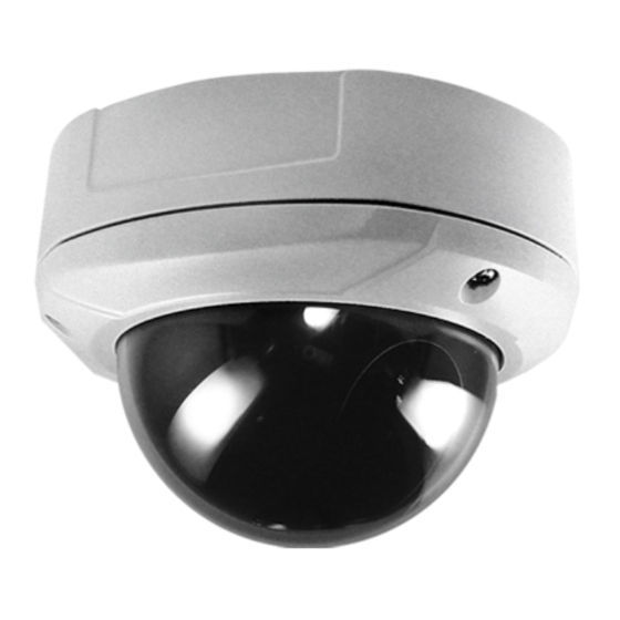
- Page 1 Digital Day & Night Color Dome Camera 사용 설명서 MANUAL 용 서 DCC-520DV...
- Page 2 The lightning flash with an arrowhead symbol, within an equilateral triangle is intended to alert the user to the presence of uninsulated dangerous voltage within the product's enclosure that may be of sufficient magnitude to constitute a risk of electric shock to persons. The exclamation point within an equilateral triangle is intended to alert the user to the presence of important operating and maintenance (servicing) instructions in the literature accompanying the appliance.
- Page 3 ■ Warning The camera needs periodic inspection. Contact an authorized technician for inspection. Stop using your camera when you find a malfunction. If you use your camera around smoke or unusual heat for a long time, fire may be caused. Do not Install the camera on a surface that can not support it.
- Page 4 ■ Precautions Only use the camera under conditions It can cause the image quality to be where temperatures are between poor. -10°C and +50°C. Be especially careful to provide ventilation when operating under high temperatures Severe lighting change or flicker can It is one of the most important parts of cause the camera to work improperly.
- Page 5 It can cause malfunctions to occur. It can damage the CCD. If it gets wet, wipe it dry immediately. If it is exposed to radioactivity, Liquids can contain minerals that For heated CCD, it will be out of order. corrode the electronic components.
-
Page 6: Table Of Contents
■ Contents 1.Features --------------------------------- 7 --------------------------------- 8 2. Components & Cable Connection 3. Names and functions of parts --------------------------------- 9 --------------------------------- 10 4. Installation & Dimension --------------------------------- 11 5. Setup Menu Operation 6. Troubleshooting --------------------------------- 26 --------------------------------- 27 7. Specification... -
Page 7: Features
1. Features ☺ Horizontal Resolution 520 TVLines Clear image quality has been achieved by employing a SONY CCD with 410,000 (effective) pixels, which provides a horizontal resolution of 520 TV lines. ☺ DAY & NIGHT This camera has a function that automatically selects the mode that is appropriate for daytime or night-time conditions. -
Page 8: Components & Cable Connection
2. Components & Cable Connection 1) Components ------------- COLOR DOME CAMERA ------------- SCREWS ------------- WRENCH MANUAL ------------- EXTRA PORT CABLE ------------- 2) Cable Connection... -
Page 9: Names And Functions Of Parts
3. Names and Functions of Parts 1) Names 2) Functions ① 3AXIS BRACKET - Please loosen screws and fix tilted and panned position. ③ LENS : Vari-Focal Auto Iris Lens ( 4.0mm ~ 9.0mm / F1.5 ) ③ OSD PCB SETUP button : Used for the menu display. -
Page 10: Installation & Dimension
4. Installation & Dimension 1) Installation Dimension... -
Page 11: Setup Menu Operation
5. Setup Menu Operation ① Please press the SETUP button Settings can now be made. The SETUP menu is displayed on the monitor. ② Green letter means, it has been selected. You may move up/down to another function by up/down buttons and change the status by pressing left/right buttons. Select any function you Modes wish to operate by using... - Page 12 1) LENS This function is used to adjust the brightness of the screen. ① Move to ‘LENS’ section of SETUP menu by up/down buttons. ② Make your choice pressing left/right key. ③ DC : Auto iris lens selection ④ MANUAL : Manual lens selection ⑤...
- Page 13 2) SHUTTER You can set up shutter speed here. ① Move to SHUTTER of the SETUP menu to change the setting by left/right key. ② Please select the SHUTTER FIXED mode by pressing the LEFT or RIGHT button. ③ Please select 'FIXED' mode if you wish to adjust the shutter manual. - You can select speed from '1/60' to '1/100,000'sec (NTSC Models), '1/50' to '1/100,000'sec (PAL Models).
- Page 14 Note) • While using the internal synchronous system, if the shutter setting is on 'AUTO' and the camera is directly facing a bright fluorescent light, the image on the screen can directly affected. Therefore please choose the installation location with care. 3) WHITE BALANCE ①...
- Page 15 and then increase or decrease the red and blue color values while monitoring the color changes on the object. Note) • Under the following conditions the WHITE BALANCE function may not operate properly. In such cases, please select the AWB mode. ①...
- Page 16 ② ON : BLC ratio can be set and you can have the camera BLC functioned only for the area of your desire. - BLC AREA : You can compensate backlight of areas you selectively want. Press SET key from ’BLC AREA’ and selected screen will disappear. Move to where you want to choose by up/down and left/right button and it will be unselected if you press once again.
- Page 17 ① Select ‘AGC’ from SETUP Menu. ② Select ON or OFF with left and right key. As the level of gain increases, the screen gets brighter and the level of noise also increases. ON : If ‘ON’ is selected you may regulate GAIN value manually. NOTE) •...
- Page 18 ① CAMERA ID If the ID is input, the camera ID appears on the monitor. Also location of CAMERA ID can be placed to which you like. - Choose ‘ON’ from CAMERA ID’ and press SET button to move to ID SETUP menu.
- Page 19 (1) Press SET button in ‘CAMERA ID’ to change CAMERA ID. (2) If it changes into ID setup status, the character with cursor can be altered. Press up/down button for change of characters, left/right to move to. Blank, 0~9, A~Z and other special characters can be input by pushing up/down button.
- Page 20 COLOR : Color mode. AUTO : This camera has a function which automatically changes to the appropriate mode for daytime or night-time. The COLOR mode is operated for daytime, and it converts to B/W mode for night-time. • DELAY : In case color mode changes into B/W mode or the opposite, you can set the DELAY time(seconds) which automatically converts.
- Page 21 Note) • When an infrared light is used, there may be a problem with focusing ③ GAMMA GAMMA level can be set by using left/right key at ‘GAMMA’ section. • Range : User, 0.05~1 ④ MOTION Motion detection function allows more effective observation. When any movement is detected, signal is generated.
- Page 22 • AREA : If SET button is pressed in ‘AREA’ section, you can select area that will detect motion. How to set up& cancel motion detected area is the same as on page No. 20 • MOTION TH : Motion sensitivity from selected area can be set up by adjusting level of MOTION THRESHOLD.
- Page 23 • AREA SEL: Choose one among 0~3 from ‘AREA SEL’ and you can set up ON/OFF status, size, color from below section. • AREA STATE: Select ON/OFF by using left/right button and let selected ‘AREA’ above activate or disable. • Adjust Size: With ’LEFT, RIGHT, TOP, BOTTOM’ on the screen you can adjust size of ‘AREA SEL’. •...
- Page 24 ⑦ LANGUAGE: English, Korean, Chinese1, Chinese2, Japanese are supported. ⑧ RESET: Status of setup value would be all RESET(default value). Press SET button at RESET section and RESET menu will appear on the screen. - YES : Status of the camera will return to default value. - NO : Cancel ‘RESET’...
- Page 25 - CONTRAST: You can adjust brightness contrast here. - SHARPNESS: Sharpness (distinction) of video can be adjusted. - CB_CR_GAIN: By adjusting CB_GAIN과 CR_GAIN you can also adjust Color Saturation. - RETURN: If setup is completed, you can press RETURN to return to previous menu.
-
Page 26: Troubleshooting
Troubleshooting If there are problems in operation, please refer to the items below. If the problem persists, please contact the agent you purchased this product from Problems Troubleshooting Nothing appears on the screen. • Please check the power connection. • Please check the video signal line connection. •... -
Page 27: Specification
7. Specification SIGNAL SYSTEM NTSC TOTAL / EFFECTIVE PIXEL 410K / 380K Pixels 470K / 440K Pixels IMAGE SENSOR 1/3” SONY interline transfer CCD HORIZONTAL RESOLUTION 520 TV Line MINIMUM ILLUMINATION 0.3 Lux / F 1.2 DAY & NIGHT ON / AUTO Available 4 ~ 9 mm DC Auto Iris Lens LENS...
Need help?
Do you have a question about the DCC-520DV and is the answer not in the manual?
Questions and answers