Table of Contents
Advertisement
Quick Links
Advertisement
Table of Contents

Related Manuals for Hand Held Products IMAGETEAM 4400


Summary of Contents for Hand Held Products IMAGETEAM 4400
- Page 1 ™ IMAGETEAM™ 4400/4700 2D Series Hand Held Imager...
-
Page 2: Statement Of Agency Compliance
Statement of Agency Compliance This device complies with part 15 of the FCC Rules. Operation is subject to the following two conditions: (1) this device may not cause harmful interference, and (2) this device must accept any interference received, including interference that may cause undesired operation. - Page 3 (i.e., power supplies, personal computers, etc.) that is not CE marked and does not comply with the Low Voltage Directive. Patents The IMAGETEAM 4400/4700 products are covered by one or more of the following U.S. Patents: 5,420,409, 5,780,834, 5,723,853; 5,723,868; 5,825,006; 5,900,613; 5,929,418. Other U.S. and foreign patents pending.
-
Page 5: Table Of Contents
Chapter 1 - Introduction and Installation About the Hand-Held 2D Imager ......... 1-1 Unpacking the Imager............1-2 IT4400 Imager Identification..........1-3 IT4700 Imager Identification..........1-4 Laser and LED Safety............1-5 Connecting the Scanner When Powered by Host (Keyboard Wedge)............. 1-6 Reading Techniques.............. - Page 6 LED Power Level..............2-17 LED Flashing ..............2-17 Aimer Delay ................ 2-18 Aimer Timeout ..............2-18 Aimer Interval ..............2-19 AutoTrigger................. 2-20 Scan Stand................2-20 Scan Stand LED Intensity..........2-20 Scan Stand Lights ............2-21 Presentation Mode............... 2-21 Presentation Reread Delay..........2-21 Presentation Default .............
- Page 7 Data Format Editor Overview ..........2-35 Format Editor Commands..........2-36 Data Format Editor ............2-38 Data Formatter ..............2-39 Require Data Format.............2-39 Show Data Formats............2-39 Alternate Data Formats..........2-40 Output Sequence Overview..........2-41 Require Output Sequence ..........2-43 Output Sequence Editor ..........2-44 Multiple Symbols ..............2-45 No Read................2-45 Print Weight ................2-46 Chapter 3 - Symbologies Introduction ................3-1...
- Page 8 EAN/JAN 8 ................. 3-13 Check Digit..............3-13 EAN/JAN 13 ............... 3-14 Check Digit..............3-14 EAN Addenda ..............3-15 UPC A ................. 3-16 Check Digit..............3-16 Number System ............3-16 UPC E0................3-17 Check Digit..............3-17 Number System ............3-17 Version E Expand............3-18 UPC E1................
- Page 9 Data Matrix................3-29 Message Length ............3-29 MaxiCode ................3-30 Message Length ............3-30 Structured Carrier Message Only .........3-31 Aztec Code ................3-32 Message Length ............3-32 VeriCode ................3-33 VeriCode Size ...............3-34 Test Menu................3-35 2D Scan Diagnostics ............3-35 Chapter 4 - OCR Programming Introduction ................4-1 OCR..................4-2 Creating OCR Templates ............4-3 Creating an OCR Template..........4-3 Stringing Together Multiple Formats...
- Page 10 Chapter 6 - Quick*View Quick*View Demonstration Software Instructions ....6-1 Setting Up the Imager and the Quick*View Software ... 6-1 Installing Quick*View from the Web ........6-2 Using the Quick*View Software .......... 6-3 Electronic Parts Manufacturing Demonstration ..... 6-6 Patient Registration Demonstration........ 6-8 Bills of Lading Demonstration ........
- Page 11 Chapter 10 - Maintenance & Troubleshooting Repairs.................10-1 Maintenance ................10-1 Replacing the Interface Cable ........10-2 Troubleshooting..............10-4 Application Support ............10-5 Chapter 11 - Customer Support Obtaining Factory Service...........11-1 Limited Warranty ..............11-3 Sample Symbols Programming Chart...
- Page 12 viii...
-
Page 13: About The Hand-Held 2D Imager
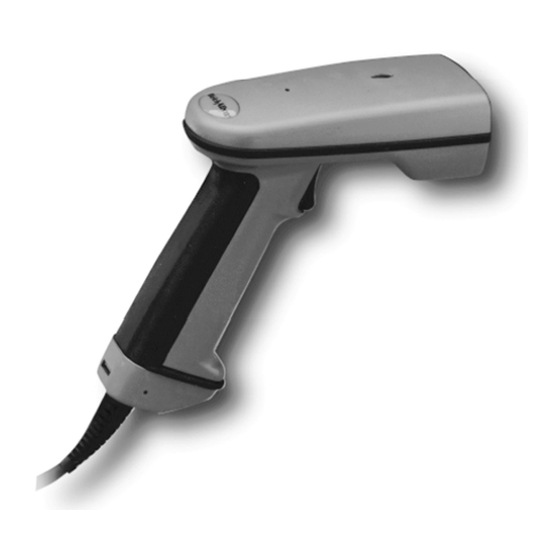
Introduction and Installation About the Hand-Held 2D Imager The hand-held 2D Imager is an economical, durable solution for a wide variety of data collection applications. The Imager features the following: • A tough, ergonomic thermoplastic housing for comfort and durability. •... -
Page 14: Unpacking The Imager
Unpacking the Imager Open the carton. The shipping carton or container should contain: IMAGETEAM 4400: IMAGETEAM 4400 Hand Held Imager Holder Visual Menu Quick*View User’s Guide Demonstration Universal Power Supply Diskettes and Power Cable IMAGETEAM 4700: IMAGETEAM 4700 Hand Held/Fixed... -
Page 15: It4400 Imager Identification
IT4400 Imager Identification Enlarged View of Label Model# = 4400XX-XX Manufactured = July 1999 Serial # = P-12-34567 S/W = 34567001/4400 Hand Held IT4400 Imager Bottom View 1 - 3... -
Page 16: It4700 Imager Identification
IT4700 Imager Identification Enlarged View of Label Hand Held IT4700 Imager Bottom View 1 - 4... -
Page 17: Laser And Led Safety
Laser and LED Safety The Laser Aiming subsystem projects 670 nm laser light onto the bar code target to define the optical field of view. The projected pattern consists of a central cross and four 90 degree corner sections. This pattern is generated by a lens and diffractive component positioned at the output of the enclosed laser diode. -
Page 18: Keyboard Wedge
Connecting the Scanner When Powered by Host (Keyboard Wedge) A scanner can be connected between the keyboard and PC as a “keyboard wedge,” plugged into the serial port, or connected to a portable data terminal in wand emulation or non decoded output mode. Note: Only units ordered from the factory with keyboard wedge capability can be connected as keyboard wedge units. -
Page 19: Reading Techniques
Reading Techniques The hand-held Imager has a view finder (shown below) which is similar to those on cameras. The view finder allows you to position the code within the field of view. The illustration below shows where to aim the red illuminated beam over the symbol for a good read. -
Page 20: Depth Of Field Charts
Depth of Field Charts Depth of Field for High Density Imager (2" Nominal Focus) Code Size Near Distance Far Distance QR 6.6 mil (0.017 cm) 1.7 inches (4.3 cm) 2.4 inches (6.1 cm) Data Matrix 6.6 mil (0.017 cm) 1.7 inches (4.3 cm) 2.4 inches (6.1 cm) Linear 4 mil (0.01 cm) 1.6 inches (4.1 cm) -
Page 21: Introduction
Programming Introduction Use this section to program the hand-held Imager. This programming section contains the following menuing selections: • General Selections • Terminal Interface Selections • Keyboard Selections • Communication Settings • Imager Selections • Output Selections • Prefix/Suffix Selections •... -
Page 22: Reset Factory Settings
Reset Factory Settings All operating parameters are stored in nonvolatile memory resident in the Imager, where they are permanently retained in the event of a power interruption. When you receive your Imager, certain operating parameters have already been set. These are the factory defaults, indicated by the symbol “ ” on the programming menu pages (beneath the default programming symbol). -
Page 23: All Symbologies
All Symbologies If you want to decode all the symbologies allowable for your scanner, scan the All Symbologies On code. All Symbologies All Symbologies Revision Selections Both the following programming codes would not normally be needed unless you have a problem with the unit. An Application Support Representative may request the boot code or power PC revision information in order to trouble shoot a problem. -
Page 24: Terminal Interface
Terminal Interface IMAGETEAM 4400 and 4700 scanners are factory programmed for a keyboard wedge interface to an IBM PC AT with a USA keyboard. If this is your interface and you do not need to modify the settings, skip to page 2-16 for Imager Selections. -
Page 25: Supported Terminals Chart
Supported Terminals Chart Terminal Terminal Model(s) I.D. PC433 SE (Portable PC) DELL Latitude (Portable PC) 486 SLC (Portable PC) Fujitsu Stylistic (Portable PC) HHLC (Code 128 Emulation) PC X PS/2 25, 30, 77DX2 AT, PS/2 30-286, 50, 55SX, 60, 70, 003, 70-061, 70-121, 80 AT Compatibles Keyboard Emulation (Non-wedge) -
Page 26: Keyboard Country
Keyboard Country Scan the Program Keyboard Country bar code below, then scan the numeric bar code(s) from the inside back cover, then the Save bar code to program the keyboard for your country. As a general rule, the following characters are not supported by the scanner for countries other than the United States: @ | $ # { } [ ] = / ‘... -
Page 27: Keyboard Style
Keyboard Style This programs keyboard styles, such as Caps Lock and Shift Lock. Default = Regular. Regular is used when you normally have the Caps Lock key off. Caps Lock is used when you normally have the Caps Lock key on. Shift Lock is used when you normally have the Shift Lock key on. -
Page 28: Keyboard Modifiers
Keyboard Modifiers This modifies special keyboard features, such as CTRL+ ASCII codes and Turbo Mode. Control + ASCII Mode On - The scanner sends key combinations for ASCII control characters for values 00-1F. Refer to "Keyboard Function Relationships" on page 2-9 for CTRL+ ASCII Values. Default = Off Control + ASCII * Control + ASCII Mode On... -
Page 29: Keyboard Function Relationships
Keyboard Function Relationships The following Keyboard Function Code, Hex/ASCII Value, and Full ASCII “CTRL”+ relationships apply to all terminals that can be used with the scanner. Function Code HEX/ASCII Value Full ASCII “CTRL” + 2 - 9... -
Page 30: Connecting The Scanner To A Serial Port
Connecting the Scanner to a Serial Port 6. Turn off power to the terminal/computer. 7. Connect the interface cable to the scanner. 8. Connect the interface cable to the 5 or 14 VDC power supply and plug in the power supply. The scanner will beep twice. 9. -
Page 31: Communication Settings
Communication Settings <Default All RS-232 Communication Settings> Parity Parity provides a means of checking character bit patterns for validity. The Imager can be configured to operate under Mark, Space, Odd, Even, or No (None) parity options. The host terminal must be set up for the same parity as the Imager, to ensure reliable communication. -
Page 32: Baud Rate
Baud Rate This sets the baud rate from 300 bits per second to 115,200 bits per second (see next page). Programming baud rate causes the data to be sent at the specified rate. The host terminal must be set to the same baud rate as the Imager to ensure reliable communication. -
Page 33: Word Length Data Bits
Baud Rate, continued 57600 115200 Word Length Data Bits You can set the Word Length at 7 or 8 bits of data per character. If an application requires only ASCII Hex characters 0 through 7F decimal (text, digits, and punctuation), select 7 data bits. For applications requiring use of the full ASCII set, select 8 data bits per character. -
Page 34: Hardware Flow Control
Hardware Flow Control When hardware flow control is on, the software checks for a CTS signal before sending data. This option is useful when your application supports the CTS signal. * Off Software Flow Control This allows control of data transmission from the Imager using software commands from the host device. -
Page 35: Serial Triggering
Serial Triggering This provides a means of sending a serial trigger command to start and stop decoding. When this feature is turned off, the Imager will not respond to serial trigger commands. When serial triggering is turned on, the Imager requires a serial trigger character to activate scanning and decoding. -
Page 36: Power Saving Mode
Power Saving Mode This provides control of the Imager’s power consumption, as follows: Low Power draws low LED current during image capture, allowing one read attempt only for each trigger pull. The Imager is less tolerant of hand movement during the read attempt, and powers down after the image capture is complete. Medium Power draws a normal LED current during image capture which enhances motion tolerance. -
Page 37: Led Power Level
LED Power Level This selection allows you to adjust LED brightness. Off is used when no illumination is needed. Low is used if low illumination is sufficient. High (the default) is the brightest setting. * High LED Flashing If LED Flashing is turned off, the average current draw is increased and the aiming light won’t illuminate while the scanner reads a bar code. -
Page 38: Aimer Delay
Aimer Delay The aimer delay allows a delay time for the operator to aim the scanner before the picture is taken. Use these codes to set the time between when the trigger is pulled and when the picture is taken. During the delay time, the aiming light will appear, but the LEDs won’t turn on until the delay time is over. -
Page 39: Aimer Interval
Aimer Interval Aimer Interval turns off the aiming light, or programs the aimer to come on at certain intervals when reading symbols with the scanner. You may program the scanner to use the aimer Every Read, Every Second Read, or Every Third Read. You may also program the scanner to use the aimer every “x”... -
Page 40: Autotrigger
AutoTrigger Two AutoTrigger Modes are available: Scan Stand and Presentation Mode. When a unit is in Scan Stand mode, the LED shines at the symbol on the base of the stand which tells it to remain idle. When a different code is presented, the Imager is triggered to read the new code. -
Page 41: Scan Stand Lights
Scan Stand Lights You can turn off the scanner light when the imager is in idle mode in a scan stand. * On Presentation Mode This programs the scanner to work in Presentation Mode. Default = Off. * Off Presentation Reread Delay This sets the time period before the scanner can read the same bar code a second time. -
Page 42: Presentation Aimer
Presentation Aimer You can turn on or off the scanner’s aiming light when the device is not reading a bar code. * On Zoom Use Zoom to zoom in and read smaller matrix codes. The zoom selection does not affect reading of linear bar codes. The factory default setting is Off. (High Density scanners are programmed with the zoom turned on when shipped from the factory. -
Page 43: Zoom Placement
Zoom Placement This lets you position the read area (crosshairs) of the Imager when it is in zoom mode. The Zoom Vertical moves the crosshairs vertically, and the Zoom Horizontal move them horizontally, as illustrated below: Note: When zoom is turned on, the field of view of the Imager is reduced, making it more difficult for the Imager to read large matrix symbols. -
Page 44: Beeper Volume
Beeper Volume * High Medium Power Up Beeper * On Output Sequence Beeper If you are using an Output Sequence (see "Output Sequence Overview" on page 2-41), you may want to hear a beep after each bar code as it is read. Scan Output Sequence Beeper On to enable this feature, or Off to disable it. -
Page 45: Beep On Decode
Beep On Decode If you want the scanner to beep each time it reads a bar code, leave this setting On. If you don’t want it to beep on each read, but do want it to beep for other events, set this selection to Off. * On Beeper Default Defaults all beeper settings. -
Page 46: And Intermessage Delays
Intercharacter, Interfunction, and Intermessage Delays Some terminals drop information (characters) if data comes through too quickly. Intercharacter, interfunction, and intermessage delays slow the transmission of data, which increases data integrity. Each delay is composed of a 5 millisecond step. You can program up to 99 steps (of 5 ms each). -
Page 47: Interfunction Delay
Interfunction Delay This is a delay of up to 495 milliseconds (in multiples of 5) placed between the transmission of each segment of the message string. You can program up to 99 steps (of 5 ms each). Scan the Interfunction Delay bar code below, then scan the number of steps, and the SAVE bar code from the inside back cover. -
Page 48: Intermessage Delay
Intermessage Delay This is a delay of up to 495 milliseconds (in multiples of 5) placed between each scan transmission. You can program up to 99 steps (of 5 ms each). Scan the Intermessage Delay bar code below, then scan the number of steps, and the SAVE bar code from the inside back cover. -
Page 49: Prefix/Suffix Overview
Prefix/Suffix Overview When a bar code is scanned, additional information is sent to the host computer along with the bar code data. This group of bar code data and additional, user-defined data is called a “message string.” The selections in this section are used to build the user-defined data into the message string. -
Page 50: Adding A Prefix Or Suffix
Adding a Prefix or Suffix 1. Scan the Add Prefix (page 2-32) or Add Suffix symbol (page 2-32). 2. Determine the 2 digit Hex value from the "Symbology Chart "on page 2-33 for the symbology to which you want to apply the prefix or suffix. 3. -
Page 51: Add A Carriage Return Suffix To All Symbologies
Add a Carriage Return Suffix to All Symbologies Scan the following bar code if you wish to add a Carriage Return Suffix to all symbologies at once. This action first clears all current suffixes, then programs a carriage return suffix for all symbologies. Add CR Suffix All Symbologies Add a Code I.D. -
Page 52: Prefix Entries
Prefix Entries Clear One Prefix † Add Prefix † Clear All Prefixes Suffix Entries Add Suffix † Clear One Suffix † Clear All Suffixes † One or more two digit numbers and Save are required after reading this programming symbol. Refer to the Programming Chart (inside back cover). Exit Selections Save Discard... -
Page 53: Symbology Chart
Symbology Chart Code Code Symbology Symbology Australian 4 State Interleaved 2 of 5 Aztec Code Japanese Postal BC412** Kix (Dutch) Postal BPO 4 State Maxicode Canadian 4 State Micro PDF417 Codabar No Read Codablock-F Code 39 PDF417 Code 49 Planet Code Code 93/93i Postnet Code 128... -
Page 54: Decimal To Hex To Ascii Conversion Chart
Decimal to Hex to ASCII Conversion Chart Dec. ASCII Dec. ASCII Dec. ASCII Dec. ASCII ‘ “ & ‘ < > 2 - 34... -
Page 55: Data Format Editor Overview
Data Format Editor Overview The Data Format Editor selections are used to edit scanned data. For example, you can use the Data Format Editor to insert characters at certain points in bar code data as it is scanned. It is not necessary to use the Data Format Editor. A set of defaults for the data format is already programmed in the scanner. -
Page 56: Format Editor Commands
Other Programming Selections • Clear One Data Format This deletes one data format for one symbology. If you are clearing the primary format, scan 0. If you are clearing an alternate format, scan 1, 2, or 3, depending on the alternate format you are clearing. Scan the Terminal Type (refer to the "Supported Terminals Chart"on page 2-5), Code I.D. - Page 57 Search Commands F8 Search ahead for “xx” character from current cursor position, leaving cursor pointing to “xx” character. Syntax = F8xx (xx stands for the hex value for an ASCII code, see "Decimal to Hex to ASCII Conversion Chart" on page 2-34.) F9 Search back for “xx”...
-
Page 58: Data Format Editor
Data Format Editor See page 2-35 through page 2-37 for a description of Data Format selections and commands. Enter Data Format † Default Data Format (none) Clear One Clear All Data Format † Data Formats Exit Selections Save Current Data Format Changes Discard Current Data Format Changes †... -
Page 59: Data Formatter
Data Formatter When Data Formatter is turned off, the bar code data is output to the host as read (including prefixes and suffixes). * On Require Data Format When Data Formatter is required, all input data must conform to an edited format or the scanner does not transmit the input data to the host device. -
Page 60: Alternate Data Formats
Alternate Data Formats Alternate formats allow you “single shot” capability to scan one bar code using a different data format than your primary format. When data formats are programmed (see page 2-35), you must input whether you are programming the primary format, or an alternate format numbered 1, 2, or 3. -
Page 61: Output Sequence Overview
Output Sequence Overview Require Output Sequence When turned off, the bar code data will be output to the host as the Imager decodes it. When turned on, all output data must conform to an edited sequence or the Imager will not transmit the output data to the host device. Note: This selection is unavailable when the Multiple Symbols Selection is turned on. - Page 62 Output Sequence Example In this example, you are scanning Codabar, Code 128, and Code 39 bar codes, but you want the scanner to output Code 39 1st, Code 128 2nd, and Codabar 3rd, as shown below. A - Code 39 B - Code 128 C-123456789B Note: To use this example, you must turn on Codabar start/stop characters (see...
-
Page 63: Require Output Sequence
Require Output Sequence When an output sequence is Required, all output data must conform to an edited sequence or the scanner will not transmit the output data to the host device. When it’s On/Not Required, the scanner will attempt to get the output data to conform to an edited sequence, but if it cannot, the scanner transmits all output data to the host device as is. -
Page 64: Output Sequence Editor
Output Sequence Editor Enter Sequence † Default Sequence Exit Selections Save Current Output Sequence Changes Discard Current Output Sequence Changes Note: If you want the scanner to beep after each bar code is read, please see "Output Sequence Beeper" on page 2-24. †... -
Page 65: Multiple Symbols
Multiple Symbols Note: This feature does not work when the Imager is in Low Power mode. When this programming selection is turned on, it allows you to read multiple symbols with a single pull of the Imager’s trigger. If you press and hold the trigger, aiming the Imager at a series of symbols, it reads unique symbols once, beeping (if turned on) for each read. -
Page 66: Print Weight
Print Weight Print Weight is used to adjust the way the scanner reads Matrix symbols. If a scanner will be seeing consistently heavily printed matrix symbols, then a print weight of 6 may improve the reading performance. For consistently light printing, a print weight of 2 may help. -
Page 67: Introduction
Symbologies Introduction Use this section to program the hand-held Imager. This programming section contains the following menuing selections: • Linear Symbology Selections • Stacked Symbology Selections • Postal Symbology Selections • 2D Matrix Symbology Selections • Diagnostics 3 - 1... -
Page 68: Codabar
Linear Symbologies Codabar <Default All Codabar Settings> Codabar * On Start/Stop Characters Start/Stop characters identify the leading and trailing ends of the bar code. You may either transmit, or not transmit Start/Stop characters. Start/Stop Transmit * Don’t Transmit Start/Stop Message Length The message length selection is used to set the valid reading length of the bar code. -
Page 69: Check Character
Linear Symbologies Codabar, continued Check Character No Check Character indicates that the scanner reads and transmits bar code data with or without a check character. When Check Character is set to Validate, But Don’t Transmit, the unit will only read Codabar bar codes printed with a check character, but will not transmit the check character with the scanned data. -
Page 70: Start/Stop Characters
Linear Symbologies Code 39 < Default All Code 39 Settings > Code 39 * On Start/Stop Characters Start/Stop characters identify the leading and trailing ends of the bar code. You may either transmit, or not transmit Start/Stop characters. * Don’t Transmit Transmit Message Length The message length selection is used to set the valid reading length of the bar... -
Page 71: Full Ascii
Linear Symbologies Code 39, continued Full ASCII If Full ASCII Code 39 decoding is turned on, certain character pairs within the bar code symbol will be interpreted as a single character. For example: $V will be decoded as the ASCII character SYN, and /C will be decoded as the ASCII character #. -
Page 72: Check Character
Linear Symbologies Code 39, continued Check Character No Check Character indicates that the scanner reads and transmits bar code data with or without a check character. When Check Character is set to Validate, But Don’t Transmit, the unit will only read Code 39 bar codes printed with a check character, but will not transmit the check character with the scanned data. -
Page 73: Interleaved 2 Of 5
Linear Symbologies Interleaved 2 of 5 < Default All Interleaved 2 of 5 Settings > Interleaved 2 of 5 * On Message Length The message length selection is used to set the valid reading length of the bar code. If the data length of the scanned bar code doesn’t match the valid reading length, the scanner will issue an error beep. -
Page 74: Check Digit
Linear Symbologies Interleaved 2 of 5, continued Check Digit When Check Digit is set to Validate, But Don’t Transmit, the unit will only read Interleaved 2 of 5 bar codes printed with a check digit, but will not transmit the check digit with the scanned data. -
Page 75: Message Length
Linear Symbologies Iata 2 of 5 < Default All Iata 2 of 5 Settings > Iata 2 of 5 * On Message Length The message length selection is used to set the valid reading length of the bar code. If the data length of the scanned bar code doesn’t match the valid reading length, the scanner will issue an error beep. -
Page 76: Message Length
Linear Symbologies Code 93 < Default All Code 93 Settings > Code 93 * On Message Length The message length selection is used to set the valid reading length of the bar code. If the data length of the scanned bar code doesn’t match the valid reading length, the scanner will issue an error beep. -
Page 77: Code 128
Linear Symbologies Code 128 < Default All Code 128 Settings > Code 128 * On Message Length The message length selection is used to set the valid reading length of the bar code. If the data length of the scanned bar code doesn’t match the valid reading length, the scanner will issue an error beep. -
Page 78: Isbt
Linear Symbologies ISBT Scan the On code below if you wish to decode ISBT bar codes. (ISBT codes are a combination of multiple linear symbols used to mark blood bags.) * Off 3 - 12... -
Page 79: Ean/Jan 8
Linear Symbologies EAN/JAN 8 < Default All EAN/JAN 8 Settings > EAN/JAN 8 * On Check Digit This selection allows you to specify whether the check digit should be transmitted at the end of the scanned data or not. * Don’t Transmit Transmit Check Digit Check Digit... -
Page 80: Ean/Jan 13
Linear Symbologies EAN/JAN 13 < Default all EAN/JAN 13 Settings > EAN/JAN 13 * On Check Digit This selection allows you to specify whether the check digit should be transmitted at the end of the scanned data or not. * Don’t Transmit Transmit Check Digit Check Digit... -
Page 81: Ean Addenda
Linear Symbologies EAN Addenda You can add 2 or 5 digits to the end of all scanned EAN data (EAN 8 and EAN 13). * 2 Digit 2 Digit Addenda On Addenda Off * 5 Digit 5 Digit Addenda On Addenda Off 3 - 15... -
Page 82: Check Digit
Linear Symbologies UPC A < Default All UPC A Settings > UPC A * On Check Digit This selection allows you to specify whether the check digit should be transmitted at the end of the scanned data or not. * Don’t Transmit Transmit Check Digit Check Digit... -
Page 83: Check Digit
Linear Symbologies UPC E0 < Default All UPC E0 Settings > UPC E0 Most UPC bar codes lead with the 0 number system. For these codes, use the UPC E0 selection. If you need to read codes which lead with the 1 number system, use the UPC E1 selection. -
Page 84: Version E Expand
Linear Symbologies UPC E0, continued Version E Expand Version E Expand, expands the UPC-E code to the 12 digit, UPC-A format. * Don’t Expand Expand UPC E1 Most UPC bar codes lead with the 0 number system. For these codes, use the UPC E0 selection. -
Page 85: Rss-14 Limited
Linear Symbologies RSS-14 < Default All RSS-14 Settings > RSS-14 Reduced Space Symbology (RSS) is a family of linear bar codes which meets restricted space requirements, while still providing full product identification. * RSS-14 On RSS-14 Off RSS-14 Limited < Default All RSS-14 Limited Settings > RSS-14 Limited * RSS-14 Limited On RSS-14 Limited Off... -
Page 86: Rss-14 Expanded
Linear Symbologies RSS-14 Expanded < Default All RSS-14 Expanded Settings > RSS-14 Expanded * RSS Expanded On RSS Expanded Off Message Length The message length selection is used to set the valid reading length of the bar code. If the data length of the scanned bar code doesn’t match the valid reading length, the scanner will issue an error beep. -
Page 87: Codablock
Stacked Symbologies Codablock < Default All Codablock Settings > Codablock * Off Message Length The message length selection is used to set the valid reading length of the bar code. If the data length of the scanned bar code doesn’t match the valid reading length, the scanner will issue an error beep. -
Page 88: Pdf417
Stacked Symbologies PDF417 < Default All PDF417 Settings > PDF417 * On Message Length The message length selection is used to set the valid reading length of the bar code. If the data length of the scanned bar code doesn’t match the valid reading length, the scanner will issue an error beep. -
Page 89: Micro Pdf417
Stacked Symbologies Micro PDF417 < Default All Micro PDF417 Settings > Micro PDF417 * Off Message Length The message length selection is used to set the valid reading length of the bar code. If the data length of the scanned bar code doesn’t match the valid reading length, the scanner will issue an error beep. -
Page 90: Message Length
Stacked Symbologies Code 49 < Default All Code 49 Settings > Code 49 * Off Message Length The message length selection is used to set the valid reading length of the bar code. If the data length of the scanned bar code doesn’t match the valid reading length, the scanner will issue an error beep. -
Page 91: Composite Codes
Stacked Symbologies Composite Codes Linear codes are combined with a unique 2D composite component to form a new class called Composite symbology. Composite symbologies allow for the co-existence of symbologies already in use. * On Message Length The message length selection is used to set the valid reading length of the bar code. -
Page 92: U.s. Postal Service Postnet Code
Postal Symbologies U.S. Postal Service POSTNET Code * Off Planet Code * Off British Post Office 4 State Code * Off Canadian 4 State Code * Off Dutch Postal Code * Off 3 - 26... -
Page 93: Australian 4 State Code
Postal Symbologies Australian 4 State Code Note: Australian 4 State Code symbology is not available in the standard IMAGETEAM 4400/4700 products, and may only be ordered by licensed users as a custom 6-digit part number. * Off Japanese Postal Service... -
Page 94: Message Length
2D Matrix Symbologies QR Code < Default All QR Code Settings > QR Code * On Message Length The message length selection is used to set the valid reading length of the bar code. If the data length of the scanned bar code doesn’t match the valid reading length, the scanner will issue an error beep. -
Page 95: Data Matrix
2D Matrix Symbologies Data Matrix < Default All Data Matrix Settings > Data Matrix * On Message Length The message length selection is used to set the valid reading length of the bar code. If the data length of the scanned bar code doesn’t match the valid reading length, the scanner will issue an error beep. -
Page 96: Maxicode
2D Matrix Symbologies MaxiCode < Default All MaxiCode Settings > MaxiCode * On Message Length The message length selection is used to set the valid reading length of the bar code. If the data length of the scanned bar code doesn’t match the valid reading length, the scanner will issue an error beep. -
Page 97: Structured Carrier Message Only
2D Matrix Symbologies MaxiCode, continued Structured Carrier Message Only A MaxiCode is made up of a primary and secondary message. The primary portion, also known as the “structured carrier message,” contains information of primary importance, such as package destination. The secondary portion contains less important data, such as package weight. -
Page 98: Aztec Code
2D Matrix Symbologies Aztec Code < Default All Aztec Code Settings > Aztec Code * On Message Length The message length selection is used to set the valid reading length of the bar code. If the data length of the scanned bar code doesn’t match the valid reading length, the scanner will issue an error beep. -
Page 99: Vericode
2D Matrix Symbologies VeriCode Note: VeriCode is a proprietary symbology, licensed to its users by Veritec, Inc. This symbology is not available in standard IMAGETEAM 4400/4700 products and may only be ordered by licensed users as a custom 6-digit part number. -
Page 100: Vericode Size
2D Matrix Symbologies VeriCode, continued VeriCode Size This selection allows you to program the Imager to read fixed VeriCode symbol sizes. If your application requires that the Imager read one fixed size, scan one of the Size menu symbols and the size (from 10 to 48, even numbers only). The size you set will be the only one turned on. -
Page 101: Test Menu
Diagnostics Test Menu When you scan the Test Menu code then scan a programming code in this manual, the scanner displays the content of a programming code. The programming function will still occur, but in addition, the content of that programming code is output to the terminal. - Page 102 Diagnostics 2D Scan Diagnostics, continued MaxiCode: Mode x, UEC = xxx% Mode x = Code structure definition UEC = Unused Error Correction Micro PDF 417: x rows, x cols, xx data & xx chks, EUC = xxx% Rows = Number of rows Cols = Number of columns Data = Number of data words Chks = Number of check words...
-
Page 103: Introduction
OCR Programming Introduction Use this section to program the hand-held Imager to read machine readable fonts used in optical character recognition (OCR). The IT4400 reads 6 to 60 point OCR typeface The IT4400/4700 will read the following fonts: • OCR-A 0123456789ABCDEFGHIJKLMNOPQRSTUVWXYZ ()<>/\+-*$ •... - Page 104 Default All OCR Settings turns off all OCR capability in the scanner, so the scanner will be able to scan linear, stacked, matrix, and composite bar codes, but not OCR fonts. In addition, any OCR templates you have created are erased. The 8 digit default templates are reinstated for any future use of the OCR On codes listed below.
-
Page 105: Creating Ocr Templates
All OCR Off turns off all OCR capability in the scanner, so the scanner will be able to scan linear, stacked, matrix, and composite bar codes, but not OCR fonts. However, any OCR templates you have created will be retained in memory. * All OCR Off Creating OCR Templates You can create a custom “template,”... - Page 106 To Add an OCR Template 1. Begin building the template. Scan the Enter OCR Template symbol (page 4-7). 2. Scan the characters for the string. Use the Template Characters chart above to determine what characters you need to create your format. Use the Programming Chart (inside back cover) to scan the characters for your template.
-
Page 107: Stringing Together Multiple Formats
4. Adding Spaces You may also need to put spaces in your template. Example C: You need to read 3 digits, space, 3 specific characters (ABC), space, 3 digits. The template: ddd2041424320ddd hex code for a space To create this template, you would scan the Enter OCR Template symbol (page 4-7), scan the “d”... -
Page 108: Creating A User-Defined Variable
Creating a User-Defined Variable You can create up to two of your own user variables for an OCR template. These variables will represent any OCR readable characters. The user-defined variables are stored under the letters “g” and “h.” Creating a user variable follows the same steps as creating a template, but instead of scanning the Enter OCR Template symbol, you scan the Enter User-Defined Variable symbol (page 4- 7). -
Page 109: Ocr Template Codes
Example F: You need to read any combination of 6 digits, with a modulo 10 check character in the 7th position. The template: ddddddc To create this template, you would scan the Modulo 10 Check Character symbol (page 4-7). Then scan the Enter OCR Template symbol, scan the “d”... -
Page 110: Exit Selections
Exit Selections Save OCR Template Discard OCR Template 4 - 8... -
Page 111: Communication (Rs-232) Selections
Default Charts The following chart lists the factory default settings (indicated by a “ ” on the programming menu pages). Parameter Default Setting Page Terminal ID page 2-4 Keyboard Country page 2-6 Keyboard Style Regular page 2-7 Control + ASCII Off page 2-8 Turbo Mode Off page 2-8... -
Page 112: Prefix/Suffix Selections
Parameter Default Setting Page Aimer Interval Every Read page 2-19 Scan Stand page 2-20 Scan Stand LED Intensity page 2-20 Scan Stand Lights page 2-21 Presentation Mode page 2-21 Presentation Reread Delay 500 ms page 2-21 Presentation Aimer page 2-22 Zoom Off - LR and XLR page 2-22... -
Page 113: Linear Symbologies
Parameter Default Setting Page Require Output Sequence Don’t Require page 2-43 No Read page 2-45 Print Weight page 2-46 Linear Symbologies Codabar page 3-2 Start/Stop Characters Don’t Transmit page 3-2 Message Length Min = 2, Max = 60 page 3-2 Check Character No Check Character page 3-3... - Page 114 Parameter Default Setting Page EAN/ JAN 13 page 3-14 Check Digit Don’t Transmit page 3-14 UPC A page 3-16 Check Digit Don’t Transmit page 3-16 Number System Transmit page 3-16 UPC E0 page 3-17 Check Digit Don’t Transmit page 3-17 Number System Don’t Transmit page 3-17...
-
Page 115: Postal Symbology Selections
Parameter Default Setting Page Composite Codes page 3-25 Message Length Min = 1, Max = 300 page 3-25 Postal Symbology Selections POSTNET Code (USPS) page 3-26 BPO 4 State Code page 3-26 Canadian 4 State Code page 3-26 Kix Code page 3-26 Australian 4 State Code page 3-27... - Page 116 5 - 6...
-
Page 117: Quick*View Demonstration Software Instructions
Quick*View is a Microsoft Windows program that displays decoded symbol messages and captures images (for instance, ID photographs) from the IMAGETEAM 4400/4700 Imager. Bar code information and images are displayed in the Quick*View window. Setting Up the Imager and the Quick*View Software 1. -
Page 118: Installing Quick*View From The Web
Installing Quick*View from the Web 1. Access the Welch Allyn DCD web site at http://dcd.welchallyn.com. 2. Click on the Support button, then click on the Software Download button. 3. When prompted, enter the user name: pumpkin and the password: pie 4. -
Page 119: Using The Quick*View Software
Using the Quick*View Software Upon startup, the Quick*View splash screen appears for approximately three seconds. Quick*View will then attempt to establish communications with the Imager. If Communication Cannot Be Established This message appears if communication cannot be established: Quick*View defaults to com 1 as the communications port. If you have plugged the Imager into another com port, you must Cancel out of this message. -
Page 120: Scan Data Window
Scan Data Window Once successful communication has been established, you can scan codes and display the bar code data in a window. Select View - Scan Data Window. As you scan bar codes, the data appears in the Serial Scan Data Window. You can alter the font in this window by using the Font button, or clear all data in the window with the Clear button. -
Page 121: Demo Screens
Demo Screens To present a demo, you must set your File - Preferences to Enable Demo Screens. Once the demo screens are enabled, scan the demo bar codes on the following pages. To disable the demo screens, click on the checkbox to remove the checkmark. -
Page 122: Electronic Parts Manufacturing Demonstration
Welch Allyn offers both long-range and high-density models of the IMAGETEAM 4400 to provide the optimal hand held solution for a wide variety of manufacturing operations. - Page 123 In an effort to reduce costs through distribution center automation, United Parcel Service (UPS) is printing a MaxiCode label on every package shipped worldwide. In this demonstration, the IMAGETEAM 4400 Imager provides a cost-effective solution for UPS personnel in hand sorting operations, and for customers who want to take advantage of the savings associated with MaxiCode without incurring the cost of an over-the-belt scanning solution.
-
Page 124: Patient Registration Demonstration
Patient Registration Demonstration Health care professionals can use two-dimensional symbologies for patient applications. In this demonstration, patient registration information is encoded on an identification card that is scanned each time the patient arrives for treatment. Both the health care professional and the patient benefit from the enhanced accuracy, efficiency, and security that photo identification provides. -
Page 125: Bills Of Lading Demonstration
Bills of Lading Demonstration Note: This demonstration is appropriate for the 4400LR and 4700LR only. Multiple linear bar codes may be replaced in a bill of lading/inventory application. In this demonstration, an individual linear code would typically be used for each part number, description, and quantity, as well as for customer and order number information. - Page 126 Signature Capture Demonstration Note: This demonstration is appropriate for the 4400LR and 4700LR only. The signature capture demo is performed by scanning the Aztec bar code below the signature box. The Aztec bar code commands the scanner to capture the image of the signature box and its contents and send this image to the host system running Quick*View.
- Page 127 Snapshot You may also use the IMAGETEAM 4400/4700 to capture an image. Click on Device - Snapshot, or click on the camera icon in the button bar to activate this feature. Resolution Snapshot icons icon Select the resolution you wish to use for this image, either Full, Half or Quarter Resolution.
- Page 128 Snapshot, continued Pull the Imager’s trigger to capture an image. Captured images appear in the Quick*View window. As you move the mouse over the image, the cursor changes to a magnifying glass. Left click to zoom in to the image, right click to zoom out. Saving an Image File If you wish to save the file as a bitmap, click on File - Save As.
-
Page 129: Open Com Port
Open Com Port If you wish to open a com port which does not have a device attached, you can do so by selecting File - Open Com Port. This dialog box appears: Click on the arrows to select the Baud Rate, Parity, and Data Bits for the com port you wish to open. -
Page 130: Load New Imager Software
Load New Imager Software If you need to upgrade the Imager’s software, you can load a new software file into the Imager’s ROM. Click on Device - Load Firmware File into ROM or click on the lightning flash icon in the button bar. Flash icon You will be... -
Page 131: Serial Programming Commands
RS-232 Serial Commands Click on View - Serial Command Window to display the Command Center window which allows you to enter serial commands to the Imager. Click on View - Scan Data Window to open a window which displays serial data in a text format. - Page 132 Responses The Imager responds to serial commands with one of three responses: ACK Indicates a good command which has been processed. ENQ Indicates a bad command. NAK Indicates the command was good, but the entry was out of the allowable range, e.g., an entry for a minimum message length of 100 when the field will only accept 2 characters.
-
Page 133: Status Check
Serial Programming Commands Selection Setting Serial Command DEFALT;MXZOOM1. DEFALT;MXZOOM1; Factory Default Settings HD10 MXZTOP6. LR/XLR DEFALT. Status Check Show Software Revision REV?. Show Data Formats DFMBK3?. Enable All Symbologies ALLENA1. Disable All Symbologies ALLENA0. Output Selections Power PC Revision REVMPC. Boot Code Revision REV_BT. -
Page 134: Communication Settings
Selection Setting Serial Command Communication Settings *Default All RS-232 232DFT. Communication Settings *None 232PARN. Mark 232PARM. Parity Space 232PARS. 232PARO. Even 232PARE. *38400 BPS 232BDR38400. 300 BPS 232BDR300. 600 BPS 232BDR600. 1200 BPS 232BDR1200. 2400 BPS 232BDR2400. Baud Rate 4800 BPS 232BDR4800. -
Page 135: Imager Selections
Selection Setting Serial Command Imager Selections PWRDFT; *Normal Power SCNLEDHIGH; HSTSSS0. PWRTIM0,TRG0, Low Power IMG1;SCNLEDLOW; Power Saving Mode HSTSSS1. PWRTIM10000, TRG0,IMG1; Medium Power SCNLEDHIGH; HSTSSS0. PWR_ON1. Power Hold Mode *Off PWR_ON0. *High SCNLEDHIGH. LED Power SCNLEDOFF. SCNLEDLOW. HSTLED0. LED Flashing HSTLED1. -
Page 136: Output Selections
Selection Setting Serial Command PRSAIM1. Presentation Aimer PRSAIM0. Disable MXZOOM0. Zoom Enable MXZOOM1. Vertical MXZTOP . Zoom Placement Horizontal MXZSID. Output Selections *High BEPVOL50. Medium BEPVOL25. Beeper Volume BEPVOL5. BEPVOL0. *Enable BEPRST1. Power Up Beeper Disable BEPRST0. BEPCLK1. Output Sequence Beeper BEPCLK0. -
Page 137: Data Formatter Selections
Selection Setting Serial Command Save Current Suffix Changes MNUSAV. Discard Current Suffix Changes MNUABT. Data Formatter Selections *No Format DFMDF3. Enter Format DFMBK3. Data Format Editor Clear One Format DFMCL3. Clear All Formats DFMCA3. Save Current Data Format Changes MNUSAV. Discard Current Data Format Changes MNUABT. - Page 138 Selection Setting Serial Command *Don’t Transmit CBRSSX0. Codabar Start/Stop Char. Transmit CBRSSX1. Minimum CBRMIN. Codabar Message Length Maximum CBRMAX. *No Check Char. CBRCHK0,CKX0. Validate, But CBRCHK1,CKX0. Codabar Check Char. Don’t Transmit Validate, CBRCHK1,CKX1. and Transmit *Default All Code 39 Code 39 C39DFT.
- Page 139 Selection Setting Serial Command A25ENA1. Iata 2 of 5 A25ENA0. Minimum A25MIN. Iata 2 of 5 Message Length Maximum A25MAX. *Default All Code 93 Code 93 C93DFT. Settings* C93ENA1. Code 93 C93ENA0. Minimum C93MIN. Code 93 Message Length Maximum C93MAX. *Default All Code 128 Code 128 128DFT.
- Page 140 Selection Setting Serial Command UPAENA1. UPC A UPAENA0. *Don’t Transmit UPACKX0. UPC A Check Digit Transmit UPACKX1. Don’t Transmit UPANSX0. UPC A Number System *Transmit UPANSX1. *Default All UPC E0 UPC E0 UE0DFT. Settings* UE0ENA1. UPC E0 UE0ENA0. *Don’t Transmit UE0CKX0.
-
Page 141: Stacked Symbology Selections
Selection Setting Serial Command Stacked Symbology Selections *Default All Codablock Set- Codablock CBFDFT. tings* CBFENA1. Codablock *Off CBFENA0. Minimum CBFMIN. Codablock Msg. Length Maximum CBFMAX. *Default All PDF417 PDF417 PDFDFT. Settings* PDFENA1. PDF417 PDFENA0. Minimum PDFMIN. PDF417 Message Length Maximum PDFMAX. -
Page 142: D Matrix Symbology Selections
Selection Setting Serial Command CANENA1. Canadian 4 State Code *Off CANENA0. *Off KIXENA0. Kix Code KIXENA1. AUSENA1. Australian 4 State Code *Off AUSENA0. JAPENA1. Japanese Postal Code *Off JAPENA0. PLENA0. Planet Code *Off PLENA1. 2D Matrix Symbology Selections *Default All QR Code QR Code Settings QRCDFT. - Page 143 Selection Setting Serial Command Minimum AZTMIN. Aztec Code Msg. Length Maximum AZTMAX. *Default All VeriCode VERDFT. VeriCode Settings Settings* VERENA1. VeriCode VERENA0. Size A VERSZA. Size B VERSZB. Size C VERSZC. VeriCode Size Size D VERSZD. Size E VERSZE. *Off TSTMNU0.
-
Page 144: Query Commands
Query Commands Several special characters can be used to query the Imager about its settings. What is the default value for the setting(s). What is the Imager’s current value for the setting(s). What is the range of possible values for the setting(s). (The Imager’s response uses a dash (-) to indicate a continuous range of values. -
Page 145: Button Bar
Example #4: What are the Imager’s settings for all Codabar selections? Enter: cbr?. Response: CBRENA1[ACK], CHK0[ACK], CKX0[ACK], SSX0[ACK], MIN2[ACK], MAX60[ACK], DFT[ACK]. This response indicates that the Imager’s Codabar Coding Enable (CBRENA) is set to 1, or on; the Check Character (CHK and CKX) is set to 0, or No Check Character; the Start/Stop Character is set to 0, or Don’t Transmit;... - Page 146 6 - 30...
-
Page 147: Visual Menu Introduction
Visual Menu Visual Menu Introduction Visual Menu provides the ability to configure a scanning device by connecting the scanner to the com port of a PC. Visual Menu allows you to download upgrades to a scanner’s firmware, change programmed parameters, and create and print programming bar codes. -
Page 148: Installing Visual Menu From The Web
Temporary Visual Menu Configuration For quick download communication configuration, scan the Visual Menu bar code to temporarily configure the scanner for Visual Menu settings. Note: If you have a unit capable of keyboard wedge mode, scan the bar code below and the unit will communicate in RS-232 mode, allowing it to work with Visual Menu. - Page 149 Interface Keys IBM AT/XT IBM, DDC, Supported and PS/2 IBM XTs and Memorex Telex, Interface Keys Compatibles, Compatibles Harris WYSE PC/AT Reserved Reserved Reserved Enter (KP) CR/Enter Enter Caps Lock Caps Lock ALT make Reserved ALT break Reserved CTRL make Reserved CTRL break Reserved...
- Page 150 IBM, Memorex Memorex Supported Interface Keys Telex (102) Telex (88) Reserved Reserved Enter Enter PF10 PF11 PF12 Reserved Reserved New Line New Line Field Forward Field Forward Reserved Tab/Field Forward Field Forward Delete Delete Field Exit New Line Insert Insert Clear Erase Error Reset...
- Page 151 Supported Esprit 200, 400 Esprit 200, 400 Esprit 200, 400 Interface Keys ANSI ASCII Reserved Reserved Reserved New Line New Line New Line New Line New Line New Line Delete New Line New Line New Line Insert Escape Escape Escape Insert Insert Home...
- Page 152 8 - 4...
-
Page 153: Product Specifications
Product Specifications & Pinouts Product Specifications Parameter Specification Dimensions 6.1 inches (15.4 cm) (4400) Length 4.85 inches (4.7 cm) (4700) Height 5.6 inches (14.2 cm) (4400) 1.85 inches (4.7 cm) (4700) Width 2.5 inches (6.3 cm) (4400 and 4700) Weight Less than 7.5 ounces (213 g), without cable Illumination Source 660 nm (±30 nm) illumination LEDs... - Page 154 Parameter Specification Ambient Light Total darkness to 100,000 Lux (sunlight) Video Image 8-bits per pixel Operating Voltage 5.0 VDC - 14.0 VDC (with cable) Current Draw - 4400 .9 A average @ 5 VDC Low Power Mode Medium Power Mode 1 A average @ 5 VDC High Power Mode 1.2 A average @ 5 VDC...
-
Page 155: Cable Pinouts
Cable Pinouts RS-232 Output, external power (IT4400 and IT4700) Decoded output data format is provided at the modular connector in the Imager.Interface cables normally supplied with the Imager are terminated with a 10 pin modular plug (P1) and a 9 pin Type D connector (P3) that is compatible with all Welch Allyn decoders and terminals. -
Page 156: It4400 Dimensions
IT4400 Dimensions 6.06 in [15.38 cm] 2.49 in Top View [6.32 cm] 1.53 in [4.01 cm] 5.62 in [14.28 cm] Front View 3/4 View 1.07 in [2.72 cm] Side View 9 - 4... -
Page 157: It4700 Dimensions
IT4700 Dimensions 4.83 in. (12.27 cm) 2.49 in. Top View (6.32 cm) 1.83 in. 1.53 in. (4.65 cm) (4.01 cm) Front View 1.63 in. (4.14 cm) 1.076 in. (2.73 cm) Side View .538 in. (1.37 cm) .630 in. (1.60 cm) M4 threaded insert .25 in. - Page 158 9 - 6...
-
Page 159: Repairs
See page 11- 1 for further information. Maintenance The IMAGETEAM 4400/IT4700 Imager provides reliable and efficient operation with a minimum of care. Although specific maintenance is not required, the following periodic checks ensure dependable Imager operation: Cleaning the Imager’s Window... -
Page 160: Replacing The Interface Cable
Examining the Imager’s Housing Routinely examine the Imager’s housing for signs of damage. A damaged housing may cause the internal components to move and may result in a malfunctioning Imager. Replacing the Interface Cable The standard interface cable is attached to the Imager with an 10-pin modular connector. - Page 161 To Replace the IT4700 Interface Cable: 1. Turn the power to the host system OFF. 2. Disconnect the Imager’s cable from the terminal or computer. 3. Insert a small, flat head screwdriver into the slot between the cable and the back end of the housing.
-
Page 162: Troubleshooting
Troubleshooting The Imager automatically performs self-tests whenever you turn it on. If your Imager is not functioning properly, review the following Troubleshooting Guide to try to isolate the problem. Troubleshooting Guide Is the power on? Are the illumination LEDs on? If the illumination LEDs in the Imager aren’t illuminated, check that: 1. -
Page 163: Application Support
Application Support If you are still experiencing problems, call your Distributor or Welch Allyn: 315-685-2476 8 a.m. to 6 p.m. EST Fax: 315-685-4960 Web Site:dcd.welchallyn.com E-Mail: dcd_techsupt@mail.welchallyn.com For more information on customer support or warranty, see the next two sections. 10 - 5... - Page 164 10 - 6...
-
Page 165: Obtaining Factory Service
Customer Support Obtaining Factory Service Welch Allyn provides service for all its products through a service center located at its manufacturing facilities in Skaneateles, New York. To obtain warranty or non-warranty service, return the unit to Welch Allyn (postage paid) with a copy of the dated purchase record attached. - Page 166 For service in Asia, please contact your Welch Allyn representative (at address below) or your local distributor. Asia/Pacific Office Welch Allyn 10/F Tung Sun Commercial Centre 194-200 Lockhart Road Wanchai, Hong Kong Telephone: Int+852-2511-3050 or 2511-3132 Fax: Int+852-251-1355 For service in Japan, please contact your Welch Allyn representative (at address below) or your local distributor.
-
Page 167: Limited Warranty
Limited Warranty Welch Allyn, Inc., hereby warrants its products to be functional and free from manufacturing defects at the time of delivery. Welch Allyn, Inc. further warrants that it will replace or repair, at its option, any unit that fails to perform according to Welch Allyn’s published specifications during a period of three (3) years from the time of shipment by Welch Allyn, Inc. - Page 168 11 - 4...
- Page 169 Add AIM I.D. Prefix to All Cable Symbologies Replacing 2-31 10-2 Serial Command Cable Pinouts 6-20 Add Code I.D. Prefix to All Carriage Return Suffix Symbologies Add to all Symbologies 2-31 2-31 Serial Command Codabar Selections 6-20 Add CR Suffix to All Symbologies Serial Commands 6-21 Codablock Selections...
- Page 170 Data Formats Serial Command 6-18 Show 2-2, 2-39 Serial Command 6-21 Data Formatter 2-39 Hardware Flow Control 2-14 Serial Command 6-21 Serial Command 6-18 Data Matrix Selections 3-29 Hex Chart 2-34 Serial Commands 6-26 Decimal to Hex to ASCII Conversion Chart 2-34 Default Settings...
- Page 171 Serial Command 6-21 Flashing Overview 2-17 Serial Command 6-19 Power Levels 2-17 Serial Command 6-19 Parity 2-11 Scan Stand Intensity 2-20 Serial Command 6-18 Serial Command 6-19 PDF 417 Selections 3-22 Scan Stand Lights Serial Commands 6-25 Serial Command 6-19 Pinouts Load New Imager Software Cables...
- Page 172 QR Code Selections Scan Data Window Serial Commands Scan Stand Selections 6-26 2-20 Query Commands Serial Command 6-28 6-19 Quick*View SCM Selections Button Bar Serial Commands 6-29 6-26 Demo Screens Serial Programming Commands 6-15 Imager Power Settings Add AIM I.D. Prefix to All 6-14 Installation Symbologies...
- Page 173 Interleaved 2 of 5 Selections Software Flow Control 6-18 Suffix 6-20 Intermessage Delay Terminal ID 6-20 6-17 ISBT UPC A Selections 6-23 6-23 Keyboard Country UPC E0 Selections 6-17 6-24 Keyboard Modifiers UPC E1 Selections 6-17 6-24 Keyboard Style User Specified Intercharacter 6-17 LED Flashing Delay...
- Page 174 Serial Command 6-17 Trigger Settings Using Quick*View 6-14 Troubleshooting 10-4 Unpacking Imager UPC A Selections 3-16 Serial Commands 6-23 UPC E0 Selections 3-17 Serial Commands 6-24 UPC E1 Selections 3-18 Serial Commands 6-24 User Specified Intercharacter Delay Serial Command 6-20 VeriCode Selections 3-33 Serial Commands...
- Page 176 Sample Symbols UPC A 0 123456 7890 Interleaved 2 of 5 1234567890 Code 128 Code 128 EAN 13 9 780330 290951 Code 39 BC321 Codabar A13579B...
-
Page 177: Sample Symbols
Sample Symbols PDF417 Car Registration Postnet Zip Code Code 49 1234567890 Data Matrix OCR-A Sample 55836540 Test Symbol QR Code OCR-B Sample 55836540 Numbers... - Page 178 Sample Symbols Aztec Package Label Aztec Mesa Code Test Message MaxiCode Test Message Micro PDF417 Test Message...
-
Page 179: Programming Chart
Programming Chart... - Page 180 Programming Chart Discard Save...
- Page 181 Programming Chart (OCR) Discard Save...
- Page 182 4619 Jordan Road P.O. Box 187 Skaneateles Falls, New York 13153-0187 44/4700/UG Rev H...