Hand Held Products 2D IMAGER 4800P User Manual
2d imager
Hide thumbs
Also See for 2D IMAGER 4800P:
- User manual (184 pages) ,
- Quick start manual (21 pages) ,
- Programming manual (1 page)
Table of Contents
Advertisement
Quick Links
Download this manual
See also:
Programming Manual
Advertisement
Table of Contents

Related Manuals for Hand Held Products 2D IMAGER 4800P


Summary of Contents for Hand Held Products 2D IMAGER 4800P
- Page 1 User’s Guide ™ 4800p 2D Imager...
-
Page 2: Fcc Compliance Statement
Hand Held Products. Hand Held Products shall not be liable for technical or editorial errors or omissions contained herein; nor for incidental or consequential damages resulting from the furnishing, performance, or use of this material. -
Page 3: Canadian Notice
FCC authorization to operate this equipment. Note: To maintain compliance with FCC Rules and Regulations, cables connected to this device must be Hand Held Products approved shielded cables, in which the cable shield wire(s) have been grounded (tied) to the connector shell. - Page 4 Hand Held Products, Inc. shall not be liable for use of our product with equipment (i.e., power supplies, personal computers, etc.) that is not CE marked and does not comply with the Low Voltage Directive. Note: To maintain compliance with FCC Rules and Regulations, cables connected to this device must be shielded cables, in which the cable shield wire(s) have been grounded (tied) to the connector shell.
- Page 5 In order to avoid the dissemination of those substances in our environment and to diminish the pressure on the natural resources, we encourage you to use the appropriate take-back systems for product disposal. Those systems will reuse or recycle most of the materials of the product you are disposing in a sound way. The crossed out wheeled bin symbol informs you that the product should not be disposed of along with municipal waste and invites you to use the appropriate separate take-back systems for product disposal.
-
Page 7: Table Of Contents
Table of Contents Chapter 1 - Getting Started About This Manual ... 1-1 Unpacking the Imager... 1-1 Imager Models ... 1-2 Imager Identification ... 1-2 Connecting the Imager with USB ... 1-3 Programming the Interface - Plug and Play... 1-4 USB PC or Macintosh USB HID... - Page 8 Decode Search Mode... 3-7 Output Sequence Overview ... 3-7 Output Sequence Editor ... 3-10 Require Output Sequence... 3-10 Print Weight... 3-11 Video Reverse... 3-11 Working Orientation... 3-12 Chapter 4 - Data Editing Prefix/Suffix Overview... 4-1 To Add a Prefix or Suffix: ... 4-2 To Clear One or All Prefixes or Suffixes:...
- Page 9 Chapter 6 - Symbologies Message Length Description... 6-2 Codabar Start/Stop Characters... 6-3 Codabar Check Character... 6-3 Codabar Concatenation ... 6-4 Codabar Message Length ... 6-5 Code 39 Start/Stop Characters... 6-6 Code 39 Check Character... 6-6 Code 39 Message Length ... 6-7 Code 39 Append...
- Page 10 UPC-E0 Check Digit... 6-23 UPC-E0 Number System ... 6-24 UPC-E0 Addenda... 6-24 EAN/JAN-13 Check Digit ... 6-25 EAN/JAN-13 Addenda ... 6-26 EAN/JAN-13 Addenda Required... 6-26 EAN/JAN-13 Addenda Separator ... 6-26 ISBN Translate... 6-27 EAN/JAN-8 Check Digit ... 6-27 EAN/JAN-8 Addenda ... 6-28 EAN/JAN-8 Addenda Required...
- Page 11 Data Matrix Message Length ... 6-48 MaxiCode Message Length... 6-49 Aztec Code Message Length ... 6-50 Aztec Runes... 6-50 Chapter 7 - Imaging Commands Image Snap - IMGSNP ... 7-1 IMGSNP Modifiers ... 7-1 Image Ship - IMGSHP... 7-2 IMGSHP Modifiers ... 7-3 Image Size Compatibility...
- Page 12 Chapter 10 - Utilities To Add a Test Code I.D. Prefix to All Symbologies... 10-1 Show Decoder Revision ... 10-1 Show Engine Revision... 10-1 Show Scan Driver Revision... 10-2 Show Software Revision... 10-2 Show Data Format ... 10-2 Resetting the Standard Product Defaults ... 10-2 Test Menu ...
- Page 13 Troubleshooting ... 13-2 Chapter 14 - Customer Support Technical Assistance... 14-1 Online Technical Assistance ... 14-2 For Further Information... 14-2 Product Service and Repair... 14-2 Online Product Service and Repair Assistance ... 14-3 Limited Warranty... 14-3 Appendix A Symbology Chart ... A-1 ASCII Conversion Chart (Code Page 1252) ...
- Page 14 viii...
-
Page 15: Chapter 1 - Getting Started
4000 Series imagers. Product specifications, dimensions, warranty, and customer support information are also included. Hand Held Products bar code imagers are factory programmed for the most common terminal and communications settings. If you need to change these settings, programming is accomplished by scanning the bar codes in this guide. -
Page 16: Imager Models
Imager Models The chart below lists the interfaces that can be used with your imager. Models Primary 4800pSF151CE USB keyboard, USB COM port emulation 4800pSF151C- USB kit 0F00E Imager Identification 1 - 2 Item Number, Serial Number and Revision Information location Compliance Label location... -
Page 17: Connecting The Imager With Usb
Connecting the Imager with USB Note: See "Imager Models" your imager. An imager can be connected to the USB port of a computer. 1. Connect the appropriate interface cable to the imager first, then to the com- puter. 2. Program the imager for a USB interface using the Plug and Play bar codes beginning on page 3. -
Page 18: Programming The Interface - Plug And Play
Programming the Interface - Plug and Play Plug and Play bar codes provide instant imager set up for commonly used interfaces. Note: After you scan one of the codes, power cycle the host terminal to have the interface in effect. Note: See "Imager Models"... -
Page 19: Usb Com Port Emulation
Scan the following code to program the imager to emulate a regular RS-232- based COM port. If you are using a Microsoft® Windows® PC, you will need to download a driver from the Hand Held Products website The driver will use the next available COM port number. Apple® Macintosh computers recognize the imager as a USB CDC class device and automatically use a class driver. -
Page 20: 4800P Stand
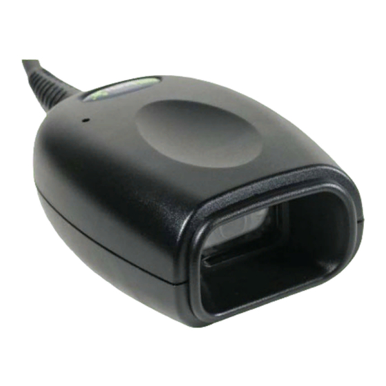
The 4800p’s viewfinder projects a green aiming beam that should be centered over the bar code, but can be positioned in any direction for a good read. Linear bar code 2D Matrix symbol Hold the scanner with the aiming beam centered over the bar code. The 4800p beeps when it successfully reads a bar code. -
Page 21: Chapter 2 - Terminal Interfaces
Terminal Interfaces Terminal ID If your interface is not covered by a Plug and Play bar code from Chapter 1, then refer to Supported Terminals on page 2-2, and locate the Terminal ID number for your PC. Scan the Terminal ID bar code below, then scan the numeric bar code(s) from the Programming Chart inside the back cover of this manual to... -
Page 22: Supported Terminals
Supported Terminals Note: See "Imager Models" your imager. Terminal USB PC Keyboard USB Mac Keyboard USB HID POS USB COM Port Emulation USB Japanese Keyboard *Default for 4800p model 2 - 2 on page 1-2 to determine which interfaces apply to Model(s) 4800p 2D Imager User’s Guide Terminal... -
Page 23: Keyboard Country
Keyboard Country Scan the appropriate country code below to program the keyboard for your country. As a general rule, the following characters are supported, but need special care for countries other than the United States: @ | $ # { } [ ] = / ‘ \ < > ~ * United States Belgium Brazil... - Page 24 Keyboard Country (continued) Italy Netherlands (Dutch) Poland Romania Spain Switzerland (German) 2 - 4 Latin America Norway Portugal Russia Slovakia Sweden 4800p 2D Imager User’s Guide...
-
Page 25: Keyboard Style
Turkey F Turkey Q U.K. Please refer to the Hand Held Products website (www.handheld.com) for complete keyboard country support information and applicable interfaces. If you need to program a keyboard for a country other than one listed above, scan the... - Page 26 Shift Lock is used when you normally have the Shift Lock key on (not common to U.S. keyboards). Shift Lock Automatic Caps Lock is used if you change the Caps Lock key on and off. The software tracks and reflects if you have Caps Lock on or off (AT and PS/2 only). This selection can only be used with systems that have an LED which notes the Caps Lock status.
-
Page 27: Keyboard Modifiers
Keyboard Modifiers This modifies special keyboard features, such as CTRL+ ASCII codes and Turbo Mode. Control + ASCII Mode On: The imager sends key combinations for ASCII control characters for values 00-1F. Refer to Keyboard Function Relationships, page 10-1 for CTRL+ ASCII Values. Default = Off Control + ASCII Mode On * Control + ASCII Mode Off Turbo Mode: The imager sends characters to a terminal faster. - Page 28 2 - 8 4800p 2D Imager User’s Guide...
-
Page 29: Chapter 3 - Output
Output Good Read Indicators Beeper – Good Read The beeper may be programmed On or Off in response to a good read. Turning this option off, only turns off the beeper response to a good read indication. All error and menu beeps are still audible. Default = On. * On Beeper Volume –... -
Page 30: Beeper Pitch - Good Read
Beeper Pitch – Good Read The beeper pitch codes modify the pitch (frequency) of the beep the imager emits on a good read. Default = Medium. Low (1600 Hz) * Medium (3250 Hz) High (4200 Hz) Beeper Duration – Good Read The beeper duration codes modify the length of the beep the imager emits on a good read. -
Page 31: Good Read Delay
Good Read Delay This sets the minimum amount of time before the imager can read another bar code. Default = No Delay. * No Delay Short Delay (500 ms) Medium Delay (1,000 ms) Long Delay (1,500 ms) User-Specified Good Read Delay If you want to set your own length for the good read delay, scan the bar code below, then set the delay (from 0-30,000 milliseconds) by scanning digits from the inside back cover, then scanning Save . -
Page 32: Reread Delay
Reread Delay This sets the time period before the imager can read the same bar code a second time. Setting a reread delay protects against accidental rereads of the same bar code. Longer delays are effective in minimizing accidental rereads. Use shorter delays in applications where repetitive bar code scanning is required. -
Page 33: Led Power Level
LED Power Level This selection allows you to adjust LED and aimer brightness. Off is used when no illumination is needed. Low is used if low illumination is sufficient. High (the default) is the brightest setting. Note: If you scan the Off bar code, both the aimer and illumination lights turn off, making it impossible to scan bar codes in low light. - Page 34 The default centering window is a 128x96 pixel area in the center of the imager’s field of view. The following diagram illustrates the default top, bottom, left, and right pixel positions, measured from the top and the left side of the imager’s field of view, which is 640 by 480 pixels.
-
Page 35: Decode Search Mode
Decode Search Mode There are three selectable decode (scanning) modes: Full Omnidirectional - Searches for bar code features beginning at the center of an image, and searches to the image’s limits. This mode reads all symbologies (including OCR), in any orientation. The Full Omnidirectional search is very thorough which may slow performance time. -
Page 36: Output Sequence Examples
Output Sequence Editor This programming selection allows you to program the imager to output data (when scanning more than one symbol) in whatever order your application requires, regardless of the order in which the bar codes are scanned. Reading the Default Sequence symbol programs the imager to the Universal values, shown below. - Page 37 Note: Code 93 must be enabled to use this example. You would set up the sequence editor with the following command line: SEQBLK62999941FF6A999942FF69999943FF The breakdown of the command line is shown below: SEQBLK sequence editor start command code identifier for Code 39 9999 code length that must match for Code 39, 9999 = all lengths start character match for Code 39, 41h = “A”...
-
Page 38: Output Sequence Editor
start character match for Code 39, 41h = “A” termination string for first code code identifier for Code 128 0013 B - Code 128 sample length (12) plus CR suffix (1) = 13 start character match for Code 128, 42h = “B” termination string for second code code identifier for Code 93 0012... -
Page 39: Print Weight
Print Weight Print Weight is used to adjust the way the imager reads Matrix symbols. If an imager will be seeing consistently heavily printed matrix symbols, then a print weight of 6 may improve the reading performance. For consistently light printing, a print weight of 2 may help. -
Page 40: Working Orientation
Working Orientation Some bar codes are direction-sensitive. For example, KIX codes and OCR can misread when scanned sideways or upside down. Use the working orientation settings if your direction-sensitive codes will not usually be presented upright to the imager. Default = Upright. Upright: Rotate Code Clockwise 90°: Upside Down:... -
Page 41: Chapter 4 - Data Editing
Data Editing Prefix/Suffix Overview When a bar code is scanned, additional information is sent to the host computer along with the bar code data. This group of bar code data and additional, user-defined data is called a “message string.” The selections in this section are used to build the user-defined data into the message string. -
Page 42: To Add A Prefix Or Suffix
To Add a Prefix or Suffix: Step 1. Scan the Add Prefix or Add Suffix symbol Step 2. Determine the 2 digit Hex value from the Symbology Chart (included in Appendix A) for the symbology to which you want to apply the prefix or suffix. -
Page 43: To Clear One Or All Prefixes Or Suffixes
To Clear One or All Prefixes or Suffixes: You can clear a single prefix or suffix, or clear all prefixes/suffixes for a symbology. When you Clear One Prefix (Suffix), the specific character you select is deleted from the symbology you want. When you Clear All Prefixes (Suffixes), all the prefixes or suffixes for a symbology are deleted. -
Page 44: Prefix Selections
Prefix Selections Add Prefix Clear All Prefixes Suffix Selections Add Suffix Clear All Suffixes Function Code Transmit When this selection is enabled and function codes are contained within the scanned data, the imager transmits the function code to the terminal. Charts of these function codes are provided in page 9-3. -
Page 45: Intercharacter, Interfunction, And Intermessage Delays
Intercharacter, Interfunction, and Intermessage Delays Some terminals drop information (characters) if data comes through too quickly. Intercharacter, interfunction, and intermessage delays slow the transmission of data, increasing data integrity. Each delay is composed of a 5 millisecond step. You can program up to 99 steps (of 5 ms each) for a range of 0-495 ms. -
Page 46: User Specified Intercharacter Delay
User Specified Intercharacter Delay An intercharacter delay of up to 495 milliseconds (in 5 ms steps) may be placed after the transmission of a particular character of scanned data. Scan the Delay Length bar code below, then scan the number of 5 millisecond steps (0-99), and the Save bar code using the Programming Chart inside the back cover of this... -
Page 47: Intermessage Delay
Intermessage Delay An intermessage delay of up to 495 milliseconds (in 5 ms steps) may be placed between each scan transmission. Scan the Intermessage Delay bar code below, then scan the number of 5 millisecond steps (0-99), and the Save bar code using the Programming Chart inside the back cover of this manual. - Page 48 4 - 8 4800p 2D Imager User’s Guide...
-
Page 49: Chapter 5 - Data Formatting
Data Formatting Data Format Editor Introduction You may use the Data Format Editor to change the imager’s output. For example, you can use the Data Format Editor to insert characters at certain points in bar code data as it is scanned. The selections in the following pages are used only if you wish to alter the output. -
Page 50: Other Programming Selections
Step 4. Code I.D. Appendix A, find the symbology to which you want to apply the data format. Locate the Hex value for that symbology and scan the 2 digit hex value from the manual. Step 5. Length Specify what length (up to 9999 characters) of data will be acceptable for this symbology. - Page 51 F4 Send “xx” character “nn” times (Insert) leaving cursor in current cursor posi- tion. Syntax = F4xxnn (xx stands for the hex value for an ASCII code, see ASCII Conversion Chart (Code Page numeric value (00-99) for the number of times it should be sent.) E9 Send all but the last “nn”...
- Page 52 ters to be replaced and xx through zz and zz E5 Terminates character replacement. Syntax = E5. FE Compare character in current cursor position to the character “xx.” If char- acters are equal, increment cursor. If characters are not equal, no format match.
-
Page 53: Data Format Editor
Data Format Editor Enter Data Format * Default Data Format Clear One Data Format Clear All Data Formats Save Discard Data Formatter When Data Formatter is turned off, the bar code data is output to the host as read (including prefixes and suffixes). Choose one of the following options. Default = Data Formatter On, but Not Required. -
Page 54: Alternate Data Formats
Alternate Data Formats Alternate formats allow you “single shot” capability to scan one bar code using a different data format than your primary format. When data formats are programmed (see page 5-1), you must input whether you are programming the primary format, or an alternate format numbered 1, 2, or 3. - Page 55 Symbologies This programming section contains the following menu selections. Refer to Chapter 11 for settings and defaults. • All Symbologies • 4-CB (4-State Customer Bar Code) • Australian Post • Aztec Code • British Post • Canadian Post • China Post •...
-
Page 56: Message Length Description
All Symbologies If you want to decode all the symbologies allowable for your imager, scan the All Symbologies On code. If on the other hand, you want to decode only a particular symbology, scan All Symbologies Off followed by the On symbol for that particular symbology. -
Page 57: Codabar Start/Stop Characters
Codabar <Default All Codabar Settings> Codabar * On Codabar Start/Stop Characters Start/Stop characters identify the leading and trailing ends of the bar code. You may either transmit, or not transmit Start/Stop characters. Default = Don’t Transmit . Transmit * Don’t Transmit Codabar Check Character Codabar check characters are created using different “modulos.”... -
Page 58: Codabar Concatenation
When Check Character is set to Validate, but Don’t Transmit , the unit will only read Codabar bar codes printed with a check character, but will not transmit the check character with the scanned data. * No Check Character Validate Modulo 16, but Don’t Transmit Validate Modulo 16 and Transmit... -
Page 59: Codabar Message Length
Select Require to prevent the imager from decoding a single “D” Codabar symbol without its companion. This selection has no effect on Codabar symbols without Stop/Start D characters. * Off Require Codabar Message Length Scan the bar codes below to change the message length. Refer to Message Length Description (page 6-2) for additional information. -
Page 60: Code 39 Start/Stop Characters
Code 39 < Default All Code 39 Settings > Code 39 * On Code 39 Start/Stop Characters Start/Stop characters identify the leading and trailing ends of the bar code. You may either transmit, or not transmit Start/Stop characters. Default = Don’t Transmit. -
Page 61: Code 39 Message Length
When Check Character is set to Validate, but Don’t Transmit, the unit only reads Code 39 bar codes printed with a check character, but will not transmit the check character with the scanned data. When Check Character is set to Validate and Transmit, the imager only reads Code 39 bar codes printed with a check character, and will transmit this character at the end of the scanned data. -
Page 62: Code 39 Append
Code 39 Append This function allows the imager to append the data from several Code 39 bar codes together before transmitting them to the host computer. When this function is enabled, the imager stores those Code 39 bar codes that start with a space (excluding the start and stop symbols), and does not immediately transmit the data. -
Page 63: Full Ascii
Full ASCII If Full ASCII Code 39 decoding is enabled, certain character pairs within the bar code symbol will be interpreted as a single character. For example: $V will be decoded as the ASCII character SYN, and /C will be decoded as the ASCII character #. -
Page 64: Code 39 Code Page
Code 39 Code Page Code pages define the mapping of character codes to characters. If the data received does not display with the proper characters, it may be because the bar code being scanned was created using a code page that is different from the one the host program is expecting. -
Page 65: Interleaved 2 Of 5 Message Length
When Check Digit is set to Validate and Transmit, the imager only reads Interleaved 2 of 5 bar codes printed with a check digit, and will transmit this digit at the end of the scanned data. Default = No Check Digit. * No Check Digit Validate, but Don’t Transmit Validate and Transmit... -
Page 66: Code 93 Message Length
Code 93 < Default All Code 93 Settings > Code 93 * On Code 93 Message Length Scan the bar codes below to change the message length. Refer to Message Length Description (page 6-2) for additional information. Minimum and Maximum lengths = 0-80. Minimum Default = 0, Maximum Default = 80. Minimum Message Length Maximum Message Length Code 93 Code Page... -
Page 67: Straight 2 Of 5 Industrial Message Length
Straight 2 of 5 Industrial <Default All Straight 2 of 5 Industrial Settings> Straight 2 of 5 Industrial * Off Straight 2 of 5 Industrial Message Length Scan the bar codes below to change the message length. Refer to Message Length Description (page 6-2) for additional information. -
Page 68: Straight 2 Of 5 Iata Message Length
Straight 2 of 5 IATA (Two-Bar Start/Stop) <Default All Straight 2 of 5 IATA Settings> Straight 2 of 5 IATA Straight 2 of 5 IATA Message Length Scan the bar codes below to change the message length. Refer to Length Description (page 6-2) for additional information. -
Page 69: Matrix 2 Of 5 Message Length
Matrix 2 of 5 <Default All Matrix 2 of 5 Settings> Matrix 2 of 5 * Off Matrix 2 of 5 Message Length Scan the bar codes below to change the message length. Refer to Message Length Description (page 6-2) for additional information. Minimum and Maximum lengths = 1-80. -
Page 70: Check Digits Required
Code 11 * Off Check Digits Required This option sets whether 1 or 2 check digits are required with Code 11 bar codes. Default = Two Check Digits. One Check Digit * Two Check Digits Code 11 Message Length Scan the bar codes below to change the message length. Refer to Message Length Description (page 6-2) for additional information. -
Page 71: Isbt 128 Concatenation
Code 128 <Default All Code 128 Settings> Code 128 * On ISBT 128 Concatenation In 1994 the International Society of Blood Transfusion (ISBT) ratified a standard for communicating critical blood information in a uniform manner. The use of ISBT formats requires a paid license. The ISBT 128 Application Specification describes 1) the critical data elements for labeling blood products, 2) the current recommendation to use Code 128 due to its high degree of security and its space-efficient design, 3) a variation of Code 128 that supports concatenation of... -
Page 72: Code 128 Message Length
Code 128 Message Length Scan the bar codes below to change the message length. Refer to Message Length Description (page 6-2) for additional information. Minimum and Maximum lengths = 0-80. Minimum Default = 0, Maximum Default = 80. Minimum Message Length Maximum Message Length Code 128 Code Page Code pages define the mapping of character codes to characters. -
Page 73: Telepen Output
Telepen <Default All Telepen Settings> Telepen * Off Telepen Output Using AIM Telepen Output, the imager reads symbols with start/stop pattern 1 and decodes them as standard full ASCII (start/stop pattern 1). When Original Telepen Output is selected, the imager reads symbols with start/stop pattern 1 and decodes them as compressed numeric with optional full ASCII (start/stop pattern 2). -
Page 74: Upc-A Check Digit
UPC-A <Default All UPC-A Settings> UPC-A * On UPC-A Check Digit This selection allows you to specify whether the check digit should be transmitted at the end of the scanned data or not. Default = On . * On UPC-A Number System The numeric system digit of a U.P.C. -
Page 75: Upc-A Addenda
UPC-A Addenda This selection adds 2 or 5 digits to the end of all scanned UPC-A data. Default = Off for both 2 Digit and 5 Digit Addenda. 2 Digit Addenda On 5 Digit Addenda On UPC-A Addenda Required When Required is scanned, the imager will only read UPC-A bar codes that have addenda. -
Page 76: Upc-E0
UPC-A/EAN-13 with Extended Coupon Code Use the following codes to enable or disable UPC-A and EAN-13 with Extended Coupon Code. Default = On. * On UPC-E0 <Default All UPC-E Settings> UPC-E0 Most U.P.C. bar codes lead with the 0 number system. For these codes, use the UPC-E0 selection. -
Page 77: Upc-E0 Addenda Required
UPC-E0 Addenda Required When Addenda Required is set to on, the imager will only read UPC-E bar codes that have addenda. Default = Not Required. Required UPC-E0 Addenda Separator When this feature is on, there is a space between the data from the bar code and the data from the addenda. -
Page 78: Upc-E0 Number System
UPC-E0 Number System The numeric system digit of a U.P.C. symbol is normally transmitted at the beginning of the scanned data, but the unit can be programmed so it will not transmit it. Default = On. * On UPC-E0 Addenda This selection adds 2 or 5 digits to the end of all scanned UPC-E data. -
Page 79: Ean/Jan-13 Check Digit
EAN/JAN-13 <Default All EAN/JAN Settings> EAN/JAN-13 * On EAN/JAN-13 Check Digit This selection allows you to specify whether the check digit should be transmitted at the end of the scanned data or not. Default = On. * On 4800p 2D Imager User’s Guide 6 - 25... -
Page 80: Ean/Jan-13 Addenda
EAN/JAN-13 Addenda This selection adds 2 or 5 digits to the end of all scanned EAN/JAN-13 data. Default = Off for both 2 Digit and 5 Digit Addenda. 2 Digit Addenda On 5 Digit Addenda On EAN/JAN-13 Addenda Required When Addenda Required is set to on, the imager will only read EAN/JAN-13 bar codes that have addenda. -
Page 81: Isbn Translate
Note: If you want to enable or disable EAN13 with Extended Coupon Code, refer to UPC-A/EAN-13 with Extended Coupon Code (page 6-22). ISBN Translate This selection causes EAN-13 Bookland symbols to be translated into their equivalent ISBN number format. Default = Off. * Off EAN/JAN-8 <Default All EAN/JAN-8 Settings>... -
Page 82: Ean/Jan-8 Addenda
EAN/JAN-8 Addenda This selection adds 2 or 5 digits to the end of all scanned EAN/JAN-8 data. Default = Off for both 2 Digit and 5 Digit Addenda. 2 Digit Addenda On 5 Digit Addenda On EAN/JAN-8 Addenda Required When Addenda Required is set to on, the imager will only read EAN/JAN-8 bar codes that have addenda. -
Page 83: Msi Check Character
<Default All MSI Settings> * Off MSI Check Character Different types of check characters are used with MSI bar codes. You can program the imager to read MSI bar codes with Type 10 check characters. Default = Validate Type 10, but Don’t Transmit. When Check Character is set to Validate and Transmit , the imager will only read MSI bar codes printed with the specified type check character, and will transmit this character at the end of the scanned data. -
Page 84: Msi Message Length
MSI Message Length Scan the bar codes below to change the message length. Refer to Length Description (page 6-2) for additional information. Minimum and Maximum lengths = 4-48. Minimum Default = 4, Maximum Default = 48. Minimum Message Length Plessey Code <Default All Plessey Code Settings>... -
Page 85: Rss Limited
RSS-14 < Default All RSS-14 Settings > RSS-14 * On RSS Limited < Default All RSS Limited Settings > RSS Limited * On RSS Expanded < Default All RSS Expanded Settings > 4800p 2D Imager User’s Guide 6 - 31... -
Page 86: Rss Expanded Message Length
RSS Expanded * On RSS Expanded Message Length Scan the bar codes below to change the message length. Refer to Message Length Description (page 6-2) for additional information. Minimum and Maximum lengths = 4-74. Minimum Default = 4, Maximum Default = 74. Minimum Message Length Maximum Message Length 6 - 32... -
Page 87: Posicode Message Length
PosiCode <Default All PosiCode Settings> PosiCode A and B * On You have to have PosiCode A and B on to read any of the PosiCode symbologies. A and B On (No Limited) A and B and Limited A On (Limited B Off) * A and B and Limited B On (Limited A Off) -
Page 88: Codablock F Message Length
Trioptic Code Note: If you are going to scan Code 32 Pharmaceutical codes Trioptic Code must be off. Trioptic Code is used for labeling magnetic storage media. Codablock F <Default All Codablock F Settings> Codablock F Codablock F Message Length Scan the bar codes below to change the message length. -
Page 89: Code 16K Message Length
Code 16K <Default All Code 16K Settings> Code 16K * Off Code 16K Message Length Scan the bar codes below to change the message length. Refer to Message Length Description (page 6-2) for additional information. Minimum and Maximum lengths = 0-160. Minimum Default = 1, Maximum Default = 160. Minimum Message Length Maximum Message Length 4800p 2D Imager User’s Guide... -
Page 90: Code 49 Message Length
Code 49 <Default All Code 49 Settings> Code 49 * On Code 49 Message Length Scan the bar codes below to change the message length. Refer to Message Length Description (page 6-2) for additional information. Minimum and Maximum lengths = 1-81. Minimum Default = 1, Maximum Default = 81. Minimum Message Length Maximum Message Length 6 - 36... -
Page 91: Pdf417 Message Length
PDF417 < Default All PDF417 Settings > PDF417 * On PDF417 Message Length Scan the bar codes below to change the message length. Refer to Message Length Description (page 6-2) for additional information. Minimum and Maximum lengths = 1-2750. Minimum Default = 1, Maximum Default = 2750. Minimum Message Length Maximum Message Length 4800p 2D Imager User’s Guide... -
Page 92: Micropdf417 Message Length
MicroPDF417 < Default All MicroPDF417 Settings > MicroPDF417 MicroPDF417 Message Length Scan the bar codes below to change the message length. Refer to Length Description (page 6-2) for additional information. Minimum and Maximum lengths = 1-366. Minimum Default = 1, Maximum Default = 366. Minimum Message Length EAN •... -
Page 93: Upc/Ean Version
UPC/EAN Version Scan the UPC/EAN Version On bar code to decode EAN•UCC Composite symbols that have a UPC or EAN linear component. (This does not affect EAN•UCC Composite symbols with a UCC/EAN-128 or RSS linear component. If either of these codes are the linear component, either Code 128 or the correct RSS code must be enabled.) UPC/EAN Version On * UPC/EAN Version Off... - Page 94 UCC Emulation • The imager can automatically format the output from any EAN•UCC data carrier to emulate what would be encoded in an equivalent UCC/EAN-128 or RSS and Composite symbol. EAN•UCC data carriers include UPC-A and UPC-E, EAN- 13 and EAN-8, ITF-14, UCC/EAN-128, and EAN•UCC RSS and Composites. Data from 2D symbols such as Aztec Code, Data Matrix, or QR Code, which encode a leading FNC1, also invoke EAN•UCC emulation.
-
Page 95: 4-Cb (4-State Customer Bar Code)
Postal Codes Note: For best performance when reading a postal symbology, all other postal symbologies should be turned off. The following postal codes can only be read by a 2D Imager. 4-CB (4-State Customer Bar Code) Note: You may enable the 4-CB (4-State Customer Bar Code) if you have firmware with a base number of 31205480. -
Page 96: Planet Code
Postnet Check Digit This selection allows you to specify whether the check digit should be transmitted at the end of the scanned data. Transmit Check Digit Planet Code Planet Code Check Digit This selection allows you to specify whether the check digit should be transmitted at the end of the scanned data. -
Page 97: British Post
British Post Canadian Post Kix (Netherlands) Post Note: Kix code can misread when scanned sideways or upside down. Use Working Orientation, page 3-12, if your Kix codes will not usually be presented upright to the imager. 4800p 2D Imager User’s Guide * Off * Off * Off... -
Page 98: Australian Post
Australian Post Australian Post Interpretation This option controls what interpretation is applied to customer fields in Australian 4-State symbols. Bar Output lists the bar patterns in “0123” format. Numeric N Table causes that field to be interpreted as numeric data using the N Table. Alphanumeric C Table causes the field to be interpreted as alphanumeric data using the C Table. -
Page 99: China Post Message Length
China Post <Default All China Post Settings> China Post * Off China Post Message Length Scan the bar codes below to change the message length. Refer to Message Length Description (page 6-2) for additional information. Minimum and Maximum lengths = 2-80. Minimum Default = 4, Maximum Default = 80. Minimum Message Length Maximum Message Length 4800p 2D Imager User’s Guide... -
Page 100: Korea Post Message Length
Korea Post <Default All Korea Post Settings> Korea Post * Off Korea Post Message Length Scan the bar codes below to change the message length. Refer to Message Length Description (page 6-2) for additional information. Minimum and Maximum lengths = 2-80. Minimum Default = 4, Maximum Default = 48. Minimum Message Length Maximum Message Length 6 - 46... -
Page 101: Qr Code Message Length
QR Code Note: QR Code can only be read by a 2D imager. < Default All QR Code Settings > QR Code This selection applies to both QR Code and Micro QR Code. * On Note: The default applies to firmware with a base number of 31205480. Refer to the Show Software Revision determining the firmware revision in your unit... -
Page 102: Data Matrix Message Length
Data Matrix Note: Data Matrix can only be read by a 2D imager. < Default All Data Matrix Settings > Data Matrix * On Data Matrix Message Length Scan the bar codes below to change the message length. Refer to Message Length Description (page 6-2) for additional information. -
Page 103: Maxicode Message Length
MaxiCode Note: MaxiCode can only be read by a 2D imager. < Default All MaxiCode Settings > MaxiCode * On MaxiCode Message Length Scan the bar codes below to change the message length. Refer to Message Length Description (page 6-2) for additional information. Minimum and Maximum lengths = 1-150. -
Page 104: Aztec Code Message Length
Aztec Code Note: Aztec Code can only be read by a 2D imager. < Default All Aztec Code Settings > Aztec Code * On Aztec Code Message Length Scan the bar codes below to change the message length. Refer to Message Length Description (page 6-2) for additional information. -
Page 105: Chapter 7 - Imaging Commands
Imaging Commands The imager can be used as a digital camera for capturing, manipulating, and transferring images. Imaging Commands with their modifiers send imaging commands to the imager on a single-use basis, and take effect for the next subsequent image capture. Once that capture is complete, the imager reverts to its imaging default settings. -
Page 106: Image Ship - Imgshp
G - Gain: This modifier boosts the signal and multiplies the pixel value. No gain (default) Medium gain Heavy gain Maximum gain D - Delta for Acceptance: This sets the allowable range for the white value setting (see W - Target White Value). Delta is only available when using Photo Style. -
Page 107: Imgshp Modifiers
The image ship command has many different modifiers that can be used to change the look of the image output by the imager. Modifiers affect the image that is transmitted, but do not affect the image in memory. Modifiers always begin with numbers and end with a letter (case insensitive). - Page 108 H - Histogram Stretch: Increases the contrast of the transmitted image. Not available with some image formats. No stretch (default) Histogram stretch I - Invert Image: Used to rotate the image around the X or Y axis in fixed mount applications where the imager is mounted upside down. Invert around the X axis (flips picture upside down) Invert around the Y axis (flips picture left to right) IF- Noise Reduction: Used to reduce the salt and pepper noise.
- Page 109 L, R, T, B, M - Image Cropping: Ships a window of the image by specifying the left, right, top, and bottom pixel coordinates. Device columns are numbered 0 through 640, and device rows are numbered 0 through 480. The left edge of the shipped image corresponds to column n of the image in memory.
-
Page 110: Image Size Compatibility
This filter typically provides better JPEG compression than the standard E - Edge Sharpen command (see shipping pure black and white images (1 bit per pixel). The optimal setting is 26U. Document image filter off (default) Apply document image filter for typical document image Apply document image filter using grayscale threshold n. -
Page 111: Intelligent Signature Capture - Imgbox
Intelligent Signature Capture - IMGBOX Note: IMGBOX commands can only be used with PDF417, Code 39, Code 128, Aztec, Codabar, and Interleaved 2 of 5 symbologies. Intelligent signature capture ships only part of an image to the host application. This method reduces transfer time and file size, while simplifying signature capture. - Page 112 F - File Format: Indicates the type of file format in which to save the image. KIM format (default) TIFF binary TIFF binary group 4, compressed TIFF grayscale Uncompressed Binary Uncompressed grayscale JPEG image Outlined image BMP format H - Height of Signature Capture Area: In the example, the height of the area to be captured is 1 inch, resulting in a value of H = 1/0.01 = 100.
-
Page 113: Chapter 8 - Ocr Programming
OCR Programming Use this section to program the Imager for optical character recognition (OCR). The 2D imager reads 6 to 60 point OCR typeface. Note: OCR is not as secure as bar codes. To enhance security in OCR applications, create an OCR template to match the data, and print an OCR check character. -
Page 114: Micr E13 B Font
OCR-B On allows you to scan characters in the OCR-B font. The default setting allows you to scan any eight digit combination. If you have created an OCR template, character combinations that fit the template can be scanned (see Creating an OCR Template, page 8-3). -
Page 115: Ocr Templates
SEMI Font SEMI Font On allows you to scan the SEMI font used in the semiconductor industry. SEMI Font On All OCR Off turns off all OCR capability in the imager, so the imager will be able to scan linear, stacked, matrix, and composite bar codes, but not OCR fonts. However, any OCR templates you have created will be retained in memory. -
Page 116: Template Characters
Template Characters represents any alphanumeric character (digit or letter) represents that a check character is verified but not transmitted represents any digit represents any available OCR character represents character from user-defined variable “g” represents character from user-defined variable “h” represents character from user-defined variable “g” or “h” represents that a check character is verified but transmitted represents any uppercase letter marks the start of a new template... - Page 117 Character Match Sequences On the ASCII Conversion Chart (Code Page value that represents the character(s) you want to match. Use the Programming Chart represent these characters. Example: You need to read three digits, three specific characters (ABC), three digits. The template would be: To create this template, you would enable the OCR-A font.
-
Page 118: Stringing Together Multiple Formats (Creating "Or" Statements)
Stringing Together Multiple Formats (Creating “Or” Statements) You may want to program the imager to accept many OCR formats. To do this, you would string together each format with a “t.” This tells the imager to read optical characters that match any one of the formats in the template. Example: You need to read any combination of eight digits, or a combination of four digits, two uppercase letters, and two digits. -
Page 119: Reading Multi-Row Ocr
This template would then let you read data that began with six digits, and had an A, B, or C trailing. So you would be able to read: Reading Multi-Row OCR The imager is capable of decoding multi-row OCR text. Note: Reading rows longer than sixteen characters is not recommended. -
Page 120: Ocr Check Character
OCR Check Character You may want to print and verify a check character in order to enhance the security of your OCR application. The imager can be programmed for almost any type of check character. A number of presets are provided for common check character uses (e.g., modulo 10 and modulo 36). -
Page 121: Ocr Modulo 36 Check Character
OCR Modulo 36 Check Character Scan this symbol to program the OCR template for a simple modulo 36 checksum of the digits 0 through 9 and the letters A through Z. OCR User-Defined Check Character You can customize the check character calculation to suit your application. Each character of the check character alphabet can be programmed in its proper order. -
Page 122: Weighting Options
2. Enter the characters in order. For each character, look up the corresponding hex value from the Use the Programming Chart scan the two symbols for each hex value. 3. Scan the Save bar code on the inside back cover. Example: To program the modulo 11 check character from example #8 on page 8-9, enable the OCR-A font. - Page 123 Since the result is zero, the message is considered to be valid, so the reader outputs the message: 0123456 2-1-2-1 Weighted Modulo 10 Check Character Starting with the check character and working backward through the message, the imager applies a multiplier of 1, then 2, then 1, then 2, and so on. When the result of the multiplication is greater than 9, add both digits to the running sum.
-
Page 124: Ocr Isbn Application Example
OCR ISBN Application Example One application of OCR is to read the ISBN characters typically encoded using the OCR-A or OCR-B font. This is especially useful when the ISBN number is not encoded in an EAN-13 bar code. The following example shows how to configure the imager to read the ISBN strings on books in Japan. -
Page 125: Ocr Template Codes
5. Finally, set up the ISBN check digit, which is a special position-weighted modulo 11 checksum. The imager automatically invokes the ISBN checksum for template rows that are: 1.) at least fourteen characters long, 2.) whose first four characters are the letters “ISBN,” 3.) whose last character is a check character, and 4.) when the modulo 11 check character “0123456789X”... -
Page 126: Exit Selections
Exit Selections Save OCR Template Discard OCR Template 8 - 14 4800p 2D Imager User’s Guide... -
Page 127: Chapter 9 - Interface Keys
Interface Keys Keyboard Function Relationships The following Keyboard Function Code, Hex/ASCII Value, and Full ASCII “CTRL”+ relationships apply to all terminals that can be used with the imager. Refer to page 2-7 enable Control + ASCII mode. Function Code HEX/ASCII Value 4800p 2D Imager User’s Guide Full ASCII “CTRL”... - Page 128 The last five characters in the Full ASCII “CTRL”+ column ( [ \ ] 6 - ), apply to US only. The following chart indicates the equivalents of these five characters for different countries. Country United States Belgium Scandinavia France Germany Italy Switzerland...
-
Page 129: Supported Interface Keys
Supported Interface Keys IBM AT/XT and PS/2 Compatibles, WYSE PC/AT ASCII Supported Keys Reserved Enter (KP) Cap Lock ALT make ALT break CTRL make CTRL break CR/Enter Reserved Reserved Delete CR/Enter Insert Escape Home Print Back Space Back Tab * IBM 3191/92, 3471/72, 3196/97, 3476/77, Telex (all models) 4800p 2D Imager User’s Guide IBM XTs and IBM, DDC, Memorex... - Page 130 Supported Interface Keys ASCII * IBM 3196/97, 3476/77, 3191/92, 3471/72, Memorex Telex (all models) with 102 key keyboards ** Memorex Telex with 88 key keyboards 9 - 4 IBM, Memorex Telex (102)* Supported Keys Reserved Enter New Line Tab/Field Forward Delete Field Exit Insert...
- Page 131 Supported Interface Keys ASCII 4800p 2D Imager User’s Guide Esprit 200, 400 Esprit 200, 400 ANSI ASCII Supported Keys Supported Keys Reserved Reserved New Line New Line New Line New Line New Line New Line Escape Escape Insert Insert Back Space Back Space Back Tab Back Tab...
- Page 132 Supported Interface Keys Apple Mac/iMac ASCII Supported Keys Reserved Enter/Numpad Enter CAPS ALT make ALT break CNTRL make CNTRL break RETURN APPLE make APPLE break RETURN Ins Help Home Prnt Scrn BACKSPACE LSHIFT TAB BACKSPACE 9 - 6 4800p 2D Imager User’s Guide...
-
Page 133: Chapter 10 - Utilities
Utilities To Add a Test Code I.D. Prefix to All Symbologies This selection allows you to turn on transmission of a Code I.D. before the decoded symbology. (See the Symbology Chart, included in the A, page A-1) for the single character code that identifies each symbology.) This action first clears all current prefixes, then programs a Code I.D. -
Page 134: Show Scan Driver Revision
Show Scan Driver Revision Scan the bar code below to output the scan driver revision. The scan driver controls image capture. You may use the Show Scan Driver Revision option if you have firmware with a base number of 31205480. Refer to the Show Software Revision below for information on determining the firmware revision in your unit. -
Page 135: Test Menu
2D PQA Reporting Hand Held Products 2D PQA reporting can be enabled in two different modes: Full Report or Screening. (To see displayed results, Microsoft® Notepad or a word processor/editing program is recommended.) -
Page 136: Visual Xpress Introduction
Note: The PQA report is sent out as a second data/beep sequence after the bar code data. The report has its own Hand Held Products code ID of >(0X3E) so it can be uniquely identified. You can exit Full Report mode by either typing the menu command, 2D_PQA0,... -
Page 137: Installing Visual Xpress From The Web
Note: Visual Xpress requires .NET software. If .NET is not installed on your PC, you will be prompted to install it during the Visual Xpress installation. 1. Access the Hand Held Products web site at www.handheld.com. 2. Click in the Quick Search text box and enter Visual Xpress. - Page 138 10 - 6 4800p 2D Imager User’s Guide...
-
Page 139: Chapter 11 - Serial Programming Commands
Serial Programming Commands The serial programming commands can be used in place of the programming bar codes. Both the serial commands and the programming bar codes will program your imager. For complete descriptions and examples of each serial programming command, refer to the corresponding programming bar code in this manual. -
Page 140: Query Commands
Query Commands Several special characters can be used to query the device about its settings. What is the default value for the setting(s). What is the device’s current value for the setting(s). What is the range of possible values for the setting(s). (The de- vice’s response uses a dash (-) to indicate a continuous range of values. -
Page 141: Examples Of Query Commands
When responding, the device echoes back the command sequence with the status character inserted directly before each of the punctuation marks (the period, exclamation point, comma, or semicolon) in the command. Examples of Query Commands In the following examples, a bracketed notation [ ] depicts a non-displayable response. -
Page 142: Resetting The Standard Product Defaults
Resetting the Standard Product Defaults If you aren’t sure what programming options are in your imager, or you’ve changed some options and want the factory settings restored, scan the Standard Product Default Settings bar code below. Standard Product Default Settings The chart on the following pages lists the factory default settings for each of the menu commands (indicated by an asterisk (*) on the programming pages). -
Page 143: Menu Commands
Menu Commands Note: Not all menu commands apply to all imager models. Selection Factory Default Settings Terminal Interfaces Terminal ID Output Selections Beeper - Good Read Beeper Volume - Good Read Beeper Pitch - Good Read (Frequency) Beeper Duration - Good Read Number of Beeps - Good Read... - Page 144 Selection LED Power Level Centering Window Decode Search Mode Output Sequence Editor Require Output Sequence Print Weight Video Reverse Working Orientation Prefix/Suffix Selections Add CR Suffix to All Symbologies 11 - 6 Setting * Indicates default Low (50%) *High (100%) Centering On *Centering Off Left of Centering Window...
-
Page 145: Data Formatter Selections
Selection Prefix Suffix Function Code Transmit Intercharacter Delay User Specified Intercharacter Delay Interfunction Delay Intermessage Delay Data Formatter Selections Data Format Editor Data Formatter Alternate Data Formats Symbologies All Symbologies Codabar Codabar 4800p 2D Imager User’s Guide Setting * Indicates default Add Prefix Clear One Prefix Clear All Prefixes... - Page 146 Selection Codabar Start/Stop Char. Codabar Check Char. Codabar Concatenation Codabar Message Length Code 39 Code 39 Code 39 Start/Stop Char. Code 39 Check Char. Code 39 Message Length Code 39 Append Code 32 Pharmaceutical (PARAF) Code 39 Full ASCII Interleaved 2 of 5 Interleaved 2 of 5 11 - 8 Setting...
- Page 147 Selection Interleaved 2 of 5 Check Digit Interleaved 2 of 5 Mes- sage Length Code 93 Code 93 Code 93 Message Length Straight 2 of 5 Industrial Straight 2 of 5 Industrial Straight 2 of 5 Industrial Message Length Straight 2 of 5 IATA Straight 2 of 5 IATA Straight 2 of 5 IATA Mes- sage Length...
- Page 148 Selection Code 11 Code 11 Check Digits Required Code 11 Message Length Code 128 Code 128 ISBT Concatenation Code 128 Message Length Code 128 Code Page Telepen Telepen Telepen Output Telepen Message Length UPC-A UPC-A UPC-A Check Digit UPC-A Number System UPC-A 2 Digit Addenda 11 - 10 Setting...
- Page 149 Selection UPC-A 5 Digit Addenda UPC-A Addenda Required UPC-A Addenda Separator UPC-A/EAN-13 with Extended Coupon Code UPC-E0 UPC-E0 UPC-E0 Expand UPC-E0 Addenda Required UPC-E0 Addenda Sepa- rator UPC-E0 Check Digit UPC-E0 Number System UPC-E0 Addenda UPC-E1 EAN/JAN-13 EAN/JAN-13 EAN/JAN-13 Check Digit 4800p 2D Imager User’s Guide Setting * Indicates default...
- Page 150 Selection EAN/JAN-13 2 Digit Addenda EAN/JAN-13 Addenda Required EAN/JAN-13 Addenda Separator ISBN Translate EAN/JAN-8 EAN/JAN-8 EAN/JAN-8 Check Digit EAN/JAN-8 Addenda EAN/JAN-8 Addenda Required EAN/JAN-8 Addenda Separator MSI Check Character MSI Message Length Plessey Code 11 - 12 Setting * Indicates default 2 Digit Addenda On *2 Digit Addenda Off 5 Digit Addenda On...
- Page 151 Selection Plessey Code Plessey Message Length RSS-14 RSS-14 RSS Limited RSS Limited RSS Expanded RSS Expanded RSS Expanded Msg. Length PosiCode PosiCode PosiCode Msg. Length Trioptic Code Codablock F Codablock F Codablock F Msg. Length 4800p 2D Imager User’s Guide Setting * Indicates default *Off...
- Page 152 Selection Code 16K Code 16K Code 16K Msg. Length Code 49 Code 49 Code 49 Msg. Length PDF417 PDF417 PDF417 Msg. Length MicroPDF417 MicroPDF417 MicroPDF417 Msg. Length EAN • UCC Composite Codes UPC/EAN Version EAN • UCC Composite Codes Msg. Length EAN•UCC Emulation TCIF Linked Code 39 (TLC39)
- Page 153 Selection ID-tag (UPU 4-State) Postnet Postnet Check Digit Planet Code Planet Code Check Digit British Post Canadian Post Kix (Netherlands) Post Australian Post Australian Post Interpre- tation Japanese Post China Post China Post China Post Msg. Length Korea Post Korea Post Korea Post Msg.
- Page 154 Selection QR Code QR Code QR Code Msg. Length Data Matrix Data Matrix Data Matrix Msg. Length MaxiCode MaxiCode MaxiCode Msg. Length Aztec Code Aztec Code Aztec Code Msg. Length Aztec Runes 11 - 16 Setting * Indicates default Default All QR Code Settings Minimum (1-3500) *1 Maximum (1-3500) *3500 Default All Data Matrix Set-...
-
Page 155: Imaging Default Commands
Selection Imaging Default Commands Image Snap 4800p 2D Imager User’s Guide Setting * Indicates default Default all Imaging Commands Imaging Style - Decoding *Imaging Style - Photo Imaging Style - Manual Beeper On *Beeper Off Exposure (1-7874 microsec- onds) *Gain - None Gain - Medium Gain - Heavy Gain - Maximum... - Page 156 Selection Image Ship 11 - 18 Setting * Indicates default *Infinity Filter - Off Infinity Filter - On *Compensation Off Compensation On *Pixel Depth - 8 bits/pixel (grayscale) Pixel Depth - 1 bit/pixel (B&W) *Don’t Sharpen Edges Sharpen Edges (0-23) *File Format - JPEG File Format - KIM File Format - TIFF binary...
-
Page 157: Ocr Selections
Selection Image Ship (continued) OCR Selections 4800p 2D Imager User’s Guide Setting * Indicates default Image Crop - Bottom (0-480) *479 Image Crop - Margin (1-238) Protocol - None (raw) Protocol - None (default USB) Protocol - Hmodem Com- pressed Protocol - Hmodem Ship Every Pixel Ship Every 2nd Pixel... - Page 158 Selection OCR Check Character OCR Templates 11 - 20 Setting * Indicates default OCR Mod. 10 Check Char. OCR Mod. 36 Check Char. OCR User-Defined Check Char. 3-1-3-1 Weighted Mod. 10 Check Char. 2-1-2-1 Weighted Mod. 10 Check Char. Enter OCR Template Enter User-Defined Variable g Enter User-Defined Variable h 4800p 2D Imager User’s Guide...
-
Page 159: Chapter 12 - Product Specifications
Product Specifications 4800p Specifications Parameter Dimensions (Typical): Height Length Width Weight Illumination: Scan LEDs Aiming LEDs Image Skew Angle Pitch Angle Motion Tolerance Symbol Contrast Voltage Requirements Current Draw (Typical): Power Supply Noise Rejection Temperature Ranges: Operating Storage Humidity Mechanical Drop Vibration ESD Tolerance 4800p 2D Imager User’s Guide... -
Page 160: Connector Pinouts
Agency Compliance Connector Pinouts 12 - 2 General: CB Scheme: IEC60950-1 I.T.E. LED Safety: Class 1 IEC 60825-1 USA: FCC Part 15, Subpart B: Class B UL: 60950-1 I.T.E. Canada: cUL: CSA C22.2 No. 60950-1 I.T.E. CAN/CSA-CEI/IEC CISPR 22-02: Class B European Community: 2004/108/EC EMC Directive, Class B 2006/95/EC Low Voltage Directive... -
Page 161: Chapter 13 - Maintenance
Inspect the imager’s interface cable and connector for wear or other signs of damage. A badly worn cable or damaged connector may interfere with imager operation. Contact your Hand Held Products distributor for information about cable replacement. Cable replacement instructions are on page 13-2. -
Page 162: Replacing The Interface Cable
The interface cable is designed to be field replaceable. • Order replacement cables from Hand Held Products or from an authorized distributor. • When ordering a replacement cable, specify the cable part number of the original interface cable. - Page 163 If the imager isn’t reading symbols well, check that the symbols: • Aren’t smeared, rough, scratched, or exhibiting voids. • Aren’t coated with frost or water droplets on the surface. • Are enabled in the imager or in the decoder to which the imager connects. Is the bar code displayed but not entered? The bar code is displayed on the host device correctly, but you still have to press a key to enter it (the Enter/Return key or the Tab key, for example).
- Page 164 13 - 4 4800p 2D Imager User’s Guide...
-
Page 165: Chapter 14 - Customer Support
Customer Support Technical Assistance If you need assistance installing or troubleshooting, please call your Distributor or the nearest Hand Held Products technical support office: North America/Canada Telephone: (800) 782-4263 Fax number: (315) 554-6705 E-mail: natechsupport@handheld.com Latin America Telephone: (803) 835-8000 Telephone: (800) 782-4263 E-mail: latechsupport@handheld.com... -
Page 166: Online Technical Assistance
Hand Held Products provides service for all its products through service centers throughout the world. To obtain warranty or non-warranty service, return the unit to Hand Held Products (postage paid) with a copy of the dated purchase record attached. Contact the appropriate location below to obtain a Return Material Authorization number (RMA #) before returning the product. -
Page 167: Online Product Service And Repair Assistance
(C) static electricity or electro-static discharge, (D) operation under conditions beyond the specified operating parameters, or (E) repair or service of the product by anyone other than Hand Held Products or its authorized representatives. This warranty shall extend from the time of shipment for the duration published by Hand Held Products for the product at the time of purchase ("Warranty... - Page 168 Hand Held Products voids the warranty. This includes but is not limited to: cables, power supplies, cradles, and docking stations. Hand Held Products, Inc. extends these warranties only to the first end- users of the products. These warranties are nontransferable.
-
Page 169: Symbology Chart
Appendix A Symbology Chart Symbology All Symbologies 4-CB (4-State Customer Bar Code) Australian Post Aztec Code British Post Canadian Post China Post Codabar Codablock F Code 11 Code 128 Code 16K Code 32 Pharmaceutical (PARAF) Code 39 Code 49 Code 93 and 93i Data Matrix EAN-13 EAN-8... - Page 170 Symbology MicroPDF417 No Read OCR-A OCR-B MICR E-13B U.S. Currency Font SEMI Font PDF417 Planet Code Plessey Code PosiCode Postnet QR/Micro QR Code Reduced Space Symbology (RSS-14, RSS Limited, RSS Expanded) Straight 2 of 5 IATA (two-bar start/ stop) TCIF Linked Code 39 (TLC39) Telepen Trioptic Code UCC/EAN-128...
- Page 171 Note: “m” represents the AIM modifier character. Refer to International Technical Specification, Symbology Identifiers, for AIM modifier character details. Note: Prefix/Suffix entries for specific symbologies override the universal (All Symbologies, 99) entry. Refer to Data Editing beginning on page 4-1 and page 5-1 for information about using Code ID and AIM ID.
-
Page 172: Ascii Conversion Chart (Code Page 1252
ASCII Conversion Chart (Code Page 1252 Note: This table applies to U.S. style keyboards. Certain characters may differ depending on your Country Code/PC regional settings. Dec Hex Char A - 4 Hex Char Dec “ & ‘ < > Char Dec Hex Char 4800p 2D Imager User’s Guide ‘... - Page 173 Char € € ‚ ƒ „ … † ‡ ˆ ‰ Š ‹ Œ Ž ‘ ’ “ ” • – — ˜ ™ š › œ ž Ÿ 4800p 2D Imager User’s Guide Char Dec ¡ ¢ £ ¤ ¥...
-
Page 174: Code Page Mapping Of Printed Bar Codes
Code Page Mapping of Printed Bar Codes Code pages define the mapping of character codes to characters. If the data received does not display with the proper characters, it may be because the bar code being scanned was created using a code page that is different from the one the host program is expecting. -
Page 175: Sample Symbols
Sample Symbols UPC-A Interleaved 2 of 5 0 123456 7890 Code 128 1234567890 EAN-13 Code 128 Code 39 9 780330 290951 Codabar BC321 Code 93 A13579B Straight 2 of 5 Industrial 123456-9$ 123456 4800p 2D Imager User’s Guide... - Page 176 Sample Symbols Matrix 2 of 5 RSS-14 6543210 PDF417 (01)00123456789012 Postnet Car Registration Zip Code Code 49 Data Matrix 1234567890 QR Code Test Symbol Numbers 4-CB (4-State Customer Bar Code) 01,234,567094,987654321,01234567891 ID-tag (UPU 4-State) J18CUSA8E6N062315014880T 4800p 2D Imager User’s Guide...
- Page 177 Sample Symbols Aztec Micro PDF417 Package Label MaxiCode Test Message OCR-B with Modulo 10 check character Test Message OCR-A with Modulo 36 check character 4800p 2D Imager User’s Guide...
-
Page 178: Ocr Programming Chart
OCR Programming Chart 4800p 2D Imager User’s Guide... - Page 179 OCR Programming Chart Discard Save 4800p 2D Imager User’s Guide...
-
Page 180: Programming Chart
Programming Chart 4800p 2D Imager User’s Guide... - Page 181 Programming Chart Save Note: If you make an error while scanning the letters or digits (before scanning Save), scan Discard, scan the correct letters or digits, and Save again. Discard...
- Page 184 Hand Held Products, Inc. 700 Visions Drive P.O. Box 208 Skaneateles Falls, NY 13153-0208 4800P-UG Rev A 10/07...
Need help?
Do you have a question about the 2D IMAGER 4800P and is the answer not in the manual?
Questions and answers