Sign In
Upload
Manuals
Brands
IEI Technology Manuals
Desktop
PPC-5xxx-9455
IEI Technology PPC-5xxx-9455 Manuals
Manuals and User Guides for IEI Technology PPC-5xxx-9455. We have
1
IEI Technology PPC-5xxx-9455 manual available for free PDF download: User Manual
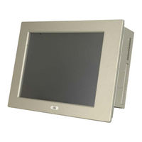
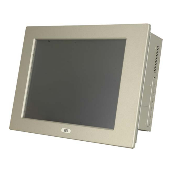
IEI Technology PPC-5xxx-9455 User Manual (198 pages)
Industrial Panel PC for LGA775 Intel Core 2 Duo TFT LCD, Dual Gigabit Ethernet, Touch Screen RoHS Compliant, IP 65 Protection
Brand:
IEI Technology
| Category:
Desktop
| Size: 13 MB
Table of Contents
Manual Conventions
4
Packing List
6
Table of Contents
7
1 Introduction
19
General Overview
20
PPC-5Xxx-9455 Model Variations
20
Figure 1-1: PPC-5Xxx-9455
20
Applications
21
Features
21
Table 1-1: PPC-5Xxx-9455 Model Variation
21
External Overview
22
Front Panel
22
Figure 1-2: Front View
22
Rear Panel
23
Top Panel
23
Figure 1-3: PPC-5Xxx-9455 Rear View
23
Figure 1-4: PPC-5Xxx-9455 Top View
23
Bottom Panel
24
Figure 1-5: Bottom View
24
Left Panel
25
Right Panel
25
Figure 1-6: Left View
25
Figure 1-7: Right View
25
Internal Overview
26
Figure 1-8: Internal Components
26
2 Specifications
27
Introduction
28
System Specifications
28
Motherboard Specifications
30
Table 2-1: PPC-5Xxx-9455 Specifications
30
Flat Panel Screen
31
PPC-5150A-9455 Screen
31
Table 2-2: Motherboard Specifications
31
PPC-5170A-9455 Screen
32
Table 2-3: 15" TFT LCD Monitor Specifications
32
PPC-5190A-9455 Screen
33
Table 2-4: 17" TFT LCD Monitor Specifications
33
Power Supply
34
Table 2-5: 19" TFT LCD Monitor Specifications
34
ACE-4518AP Power Supply
35
Table 2-6: ACE-4518AP Power Supply Specifications
35
ACE-4520C Power Supply
36
Dimensions
36
Table 2-7: ACE-4520C Power Supply Specifications
36
Figure 2-1: PPC-5150A-9455 Dimensions (Units in MM)
37
PPC-5150A-9455 Dimensions
37
Figure 2-2: PPC-5170A-9455 Dimensions (Units in MM)
38
PPC-5170A-9455 Dimensions
38
Figure 2-3: PPC-5190A-9455 Dimensions (Units in MM)
39
PPC-5190A-9455 Dimensions
39
Motherboard
40
Cpu Support
40
System Chipsets
40
Figure 2-4: POS-9455 Motherboard
40
ICH7 Southbridge Chipset
41
Intel® 945G Northbridge Chipset
41
Graphics Support
42
Analog CRT Support
43
LVDS Support
43
Memory
43
Storage
44
Compactflash
44
Figure 2-5: SO-DIMM Socket
44
SATA Hard Drive
45
Figure 2-6: Compactflash® Slot
45
Expansion Slots
46
Figure 2-7: SATA Hard Drive Slot
46
Figure 2-8: Expansion Card Slot
46
External Device Connectors
47
USB 2.0 Ports
47
Figure 2-9: USB Ports
47
Serial Ports
48
Parallel Port
48
Figure 2-10: Serial Ports
48
Figure 2-11: Parallel Port
48
Gigabit Ethernet
49
Front Panel
49
Figure 2-12: Ethernet
49
Flat Screen
50
Touch Screen
50
Oem Options
50
3 Unpacking
51
Anti-Static Precautions
52
Unpacking Precautions
52
Package Contents
53
Table 3-1: Package List Contents
54
4 Installation and Configuration
55
Installation Precautions
56
Preinstalled Components
56
Installation and Configuration Steps
57
Remove the
58
Figure 4-1: Back Cover Retention Screws
58
Cover
58
Jumper Settings
59
AT/ATX Power Selection (AT_PWR_SW1)
60
Clear CMOS Setup (JP2)
60
Table 4-1: Onboard Jumpers
60
Table 4-2: AT/ATX Power Selection
60
Monitor Setup (JP1)
61
Table 4-3: Clear CMOS Jumper Settings
61
Table 4-4: LCD Resolution Settings
61
Table 4-5: Monitor Settings
61
CF Card Setup (JP7)
62
COM Port RI and Voltage Selection (JP3, JP4, JP5, JP6, JP8)
62
Table 4-6: CF Card Setup Jumper Settings
62
Table 4-7: COM1 RI and Voltage Selection Jumper
62
Table 4-8: COM2 RI and Voltage Selection Jumper
62
Table 4-9: COM3 RI and Voltage Selection Jumper
62
COM5 RS-232/422/485 Settings
63
COM5 RS-232/422/485 RX Select (J2)
63
COM5 RS-422/485 TX Select (J3)
63
Table 4-10: COM4 RI and Voltage Selection Jumper
63
Table 4-11: COM5 RI and Voltage Selection Jumper
63
Table 4-12: COM5 RS-232/422/485 RX Select
63
Table 4-13: COM5 RS-422/485 TX Select
63
COM5 D-Sub Pinout Selection (J4)
64
COM5 Termination Resistors (J5, J6)
64
LCD Voltage Settings (JP9)
64
Table 4-14: COM5 RS-422/485 TX Select
64
Table 4-15: COM5 RS-422/485 TX Select
64
Table 4-16: LCD Voltage Settings
64
Touch Screen Selection (JP7)
65
Drive Installation
65
Hard Drive Installation
65
Table 4-17: Touch Screen Selection
65
Figure 4-2: HDD Retention Screws
66
Figure 4-3: HDD SATA Connector
66
Figure 4-4: HDD Retention Screws
67
Figure 4-5: HDD Retention Screws
67
Compactflash Installation
68
Figure 4-6: Compactflash® Cover Plate
68
Figure 4-7: Compactflash® Slot
68
CD Drive Installation
69
Figure 4-8: Compactflash® Cover Plate
69
Figure 4-9: CD Drive Adapter Installation
69
Figure 4-10: CD Drive Retention Screws
70
Figure 4-11: Optical Drive Blank Plate Assembly
70
Figure 4-12: Optical Drive Screws
71
Figure 4-13: Optical Drive SATA Cable
72
Figure 4-14: Optical Drive Bracket Screws
72
Mounting the System
73
Wall Mounting
73
Figure 4-15: Wall-Mounting Bracket
74
Figure 4-16: Mount the Chassis
75
Panel/ Mounting
76
Figure 4-17: Secure the Chassis
76
Figure 4-18: 15" Panel Cutout Dimensions
77
Figure 4-19: 17" Panel Cutout Dimensions
77
Figure 4-20: 19" Panel Cutout Dimensions
78
Rack and Cabinet Installation
79
Figure 4-21: Panel Mounting Clamp Positions
79
Figure 4-22: Tighten the Panel Mounting Clamp Screws
79
Arm Mounting
80
External Peripheral Interface Connectors
81
LCD Panel Connection
81
Ethernet Connection
81
Figure 4-23: Arm Mount Retention Screw Holes
81
USB Connection
82
Keyboard and Mouse Connection
82
Parallel Port Connection
82
Serial Port Connection
82
Audio Port Connection
82
5 Bios Setup
83
Introduction
84
Starting Setup
84
Using Setup
84
Getting Help
85
Unable to Reboot after Configuration Changes
85
BIOS Menu Bar
85
Table 5-1: BIOS Navigation Keys
85
Main
86
BIOS Menu 1: Main
86
Advanced
87
BIOS Menu 2: Advanced
88
BIOS Menu 3: CPU Configuration
89
CPU Configuration
89
IDE Configuration
91
BIOS Menu 4: IDE Configuration
91
BIOS Menu 5: IDE Master and IDE Slave Configuration
93
IDE Master, IDE Slave
93
BIOS Menu 6: IDE Master and IDE Slave Configuration
98
Floppy Configuration
98
BIOS Menu 7: Super IO Configuration
99
Super IO Configuration
99
BIOS Menu 8: Hardware Health Configuration
104
Hardware Health Configuration
104
Power Configuration
109
BIOS Menu 9: ACPI Configuration
109
ACPI Configuration
110
BIOS Menu 10: ACPI Configuration
110
APM Configuration
111
BIOS Menu 11:Advanced Power Management Configuration
111
BIOS Menu 12: Remote Access Configuration [Advanced]
114
Remote Access Configuration
114
USB Configuration
117
BIOS Menu 13: USB Configuration
117
BIOS Menu 14: USB Mass Storage Device Configuration
119
USB Mass Storage Device Configuration
119
Pci/Pnp
121
BIOS Menu 15: Pci/Pnp Configuration
121
Boot
123
BIOS Menu 16: Boot
123
BIOS Menu 17: Boot Settings Configuration
124
Boot Settings Configuration
124
BIOS Menu 18: Boot Device Priority Settings
126
Boot Device Priority
126
Hard Disk Drives
126
BIOS Menu 19: Hard Disk Drives
127
CD/DVD Drives
128
BIOS Menu 20: CD/DVD Drives
129
Security
130
BIOS Menu 21: Security
130
Chipset
131
BIOS Menu 22: Chipset
131
BIOS Menu 23:Northbridge Chipset Configuration
132
Northbridge Configuration
132
BIOS Menu 24:Southbridge Chipset Configuration
134
Southbridge Configuration
134
Exit
135
BIOS Menu 25:Exit
135
6 Software Installation
137
Available Software Drivers
138
Chipset Driver
138
Figure 6-1: Chipset Driver Installation Program
139
Figure 6-2: Chipset Driver Installation Welcome Screen
139
Figure 6-3: Chipset Driver Installation License Agreement
140
Figure 6-4: Chipset Driver Readme File Information
140
Figure 6-5: Chipset Driver Installation Complete
141
Graphics Driver
142
Figure 6-6: Chipset Driver Installation Complete
142
Figure 6-7: Graphics Setup Icon
143
Figure 6-8: VGA Driver
143
Figure 6-9: Graphics Driver Installation
144
Figure 6-10: Graphics Driver License Agreement
144
Figure 6-11: Graphics Driver Readme File
145
Figure 6-12: Graphics Driver Installation Notice
146
Figure 6-13: Graphics Driver Installation Complete
146
Gigabit Ethernet Driver Installation
147
Figure 6-14: Windows Control Panel
148
Figure 6-15: System Icon
148
Figure 6-16: Device Manager Tab
149
Figure 6-17: Device Manager List
150
Figure 6-18: Search Windows Update Prompt
150
Figure 6-19: Search Windows Update Prompt
151
Audio Driver
152
BIOS Setup
152
Driver Installation
152
Figure 6-20: Hardware Installation Complete
152
Figure 6-21: Select the Audio CODEC
153
Figure 6-22: Audio Driver Installation
153
Figure 6-23: Windows Logo Testing
154
Figure 6-24: Installshield Wizard Complete
154
Touch Panel Driver
155
Figure 6-25: S-Video Patch Folder
155
Figure 6-26: Touch Panel Driver Welcome Screen
155
Figure 6-27: Touch Panel License Agreement
156
Figure 6-28: Touch Panel Installation Directory
157
Figure 6-29: Touch Panel Drivers Installing
157
Figure 6-30: Windows Logo Testing
158
Figure 6-31: Installshield Wizard Complete
158
7 System Maintenance
159
System Maintenance Introduction
160
Motherboard Replacement
160
Back Cover Removal
160
DIMM Replacement
161
Elevated Platform Removal
162
Figure 7-1: DIMM Socket Clip Locations
162
Figure 7-2: Top Panel Elevated Platform Screws
162
Figure 7-3: Side Panel Elevated Platform Screws
163
Figure 7-4: Bottom Panel Elevated Platform Screws
163
Psu Module Replacement
164
Remove the Old PSU
164
Figure 7-5: Internal Elevated Platform Screws
164
Figure 7-6: PSU Power Cables
165
Figure 7-7: PSU Bottom Panel Retention Screws
165
Install the New PSU
166
Figure 7-8: PSU Rear Panel Screws
166
System Cooling Fan Replacement
167
Remove the Old System Cooling Fans
167
Figure 7-9: System Cooling Fans Motherboard Connector
167
Install the New System Cooling Fans
168
Figure 7-10: System Cooling Fans Left Panel Retention Screws
168
ABIOS Options
169
B Terminology
173
C Digital I/O Interface
177
Introduction
178
Dio Connector Pinouts
178
Assembly Language Samples
179
Enable the DIO Input Function
179
Enable the DIO Output Function
179
D Watchdog Timer
180
E Address Mapping
183
Direct Memory Access (Dma)
184
A Ccess (Dma)
184
Input/Output (IO)
185
Interrupt Request (Irq)
187
R Equest (Irq)
187
Memory
188
F Compatibility
189
Compatible Operating Systems
190
Compatible Processors
190
Compatible Memory Modules
191
G Hazardous Materials Disclosure
192
Hazardous Materials Disclosure Table for Ipb Products Certified as
193
Advertisement
Advertisement
Related Products
IEI Technology PPC-5150A-H61-P/R-R10
IEI Technology PPC-5150AD-H61-P/R-R10
IEI Technology PPC-5150A-H61-i3/R-R10
IEI Technology PPC-5150A-H61-i5/R-R10
IEI Technology PPC-5170A-H61-P/R-R10
IEI Technology PPC-5170AD-H61-P/R-R10
IEI Technology PPC-5170A-H61-i5/R-R10
IEI Technology PPC-5190A-H61-i3/R-R10
IEI Technology PPC-5190A-H61-i5/R-R10
IEI Technology PPC-5190AD-H61-P/R-R10
IEI Technology Categories
Motherboard
Touch Panel
Computer Hardware
Single board computers
Desktop
More IEI Technology Manuals
Login
Sign In
OR
Sign in with Facebook
Sign in with Google
Upload manual
Upload from disk
Upload from URL