Table of Contents
Advertisement
Quick Links
Advertisement
Chapters
Table of Contents

Related Manuals for IEI Technology POC-3174B-A330


Summary of Contents for IEI Technology POC-3174B-A330
- Page 1 POC-3174B-A330 Medical Panel PC POC-3174B-A330 Medical Panel PC Page I...
- Page 2 POC-3174B-A330 Medical Panel PC Revision Date Version Changes 2008-11 1.00 Initial release Page II...
- Page 3 POC-3174B-A330 Medical Panel PC Copyright COPYRIGHT NOTICE The information in this document is subject to change without prior notice in order to improve reliability, design and function and does not represent a commitment on the part of the manufacturer. In no event will the manufacturer be liable for direct, indirect, special, incidental, or consequential damages arising out of the use or inability to use the product or documentation, even if advised of the possibility of such damages.
-
Page 4: Manual Conventions
Cautionary messages should also be heeded to help reduce the chance of losing data or damaging the POC-3174B-A330. Cautions are easy to recognize. The word “caution” is written as “CAUTION,” both capitalized and bold and is followed. The italicized text is the cautionary message. - Page 5 “NOTE,” both capitalized and bold and is followed by text. The text is the cautionary message. A note message is shown below: NOTE: This is an example of a note message. Notes should always be read. Notes contain critical information about the POC-3174B-A330. Please take note messages seriously. Page V...
- Page 6 POC-3174B-A330 from or contact an IEI sales representative directly. To contact an IEI sales representative, please send an email to sales@iei.com.tw. The items listed below should all be included in the POC-3174B-A330 package. 1 x POC-3174B-A330 medical panel PC 1 x Power cord (Europe standard)
-
Page 7: Table Of Contents
POC-3174B-A330 Medical Panel PC Table of Contents INTRODUCTION....................1 1.1 G ....................2 ENERAL VERVIEW 1.1.1 Features and Model Variation ................3 1.2 E ....................3 XTERNAL VERVIEW 1.2.1 Front Panel ......................3 1.2.2 Rear Panel ......................5 1.2.3 Bottom Panel...................... 5 1.2.4 Side Panel ...................... - Page 8 POC-3174B-A330 Medical Panel PC 2.7 A ........................17 UDIO 2.7.1 High Definition Audio Controller ..............17 2.7.2 Stereo Speakers ....................18 2.8 S ....................... 18 YSTEM OWER 2.8.1 Power Adapter ....................18 2.8.2 Power Connector ..................... 19 2.8.3 Lithium Battery ....................19 2.8.4 Power Mode .....................
- Page 9 POC-3174B-A330 Medical Panel PC SYSTEM MAINTENANCE ................46 5.1 I ......................47 NTRODUCTION 5.2 M ................47 OTHERBOARD EPLACEMENT 5.3 P ................47 LASTIC OVER EMOVAL 5.4 HDD R ....................49 EPLACEMENT 5.5 M ................50 EMORY ODULE EPLACEMENT 5.6 J ....................
- Page 10 POC-3174B-A330 Medical Panel PC 6.7.1 North Bridge Configuration................92 6.7.2 South Bridge Configuration................94 6.7.3 Power Configuration ..................95 6.7.4 Advanced Power Configuration............... 96 6.8 E ......................... 99 SOFTWARE DRIVERS................... 101 7.1 A ................102 VAILABLE OFTWARE RIVERS 7.2 I ®...
- Page 11 POC-3174B-A330 Medical Panel PC A.6 W LAN M ..................145 IRELESS ODULE SAFETY PRECAUTIONS................146 B.1 S ................... 147 AFETY RECAUTIONS B.1.1 General Safety Precautions ................147 B.1.2 Explanation of Graphical Symbols..............148 B.1.3 Classification....................148 B.1.4 Anti-static Precautions .................. 149 B.1.5 Product Disposal ...................
- Page 12 Figure 1-3: Rear View....................5 Figure 1-4: Bottom View ....................6 Figure 1-5: Left View .....................7 Figure 2-1: POC-3174B-A330 Dimensions (units in mm) ........11 Figure 2-2: Memory Module and Memory Socket ............12 Figure 2-3: COM Ports ....................14 Figure 2-4: RJ-45 Ethernet Connectors ..............14 Figure 2-5: RJ-45 Remote Control Connector............15...
- Page 13 POC-3174B-A330 Medical Panel PC Figure 4-9: Secure the Panel PC................37 Figure 4-10: Arm Mounting Retention Screw Holes ..........38 Figure 4-11: Audio Connectors..................39 Figure 4-12: DVI Connector..................40 Figure 4-13: LAN Connection..................41 Figure 4-14: PS/2 Keyboard/Mouse Connector............42 Figure 4-15: Serial Device Connector ...............43 Figure 4-16: USB Device Connection................44...
- Page 14 POC-3174B-A330 Medical Panel PC Figure 7-16: RTL8111CP Drivers Installing ............111 Figure 7-17: RTL8111CP InstallShield Wizard............111 Figure 7-18: RTL8111CP Driver Installation Complete......... 112 Figure 7-19: The InstallShield Wizard Starts ............113 Figure 7-20: Preparing Setup Screen ..............113 Figure 7-21: InstallShield Wizard Welcome Screen..........114 Figure 7-22: Audio Driver Software Configuration ..........
- Page 15 POC-3174B-A330 Medical Panel PC Figure 8-12: LAN Setting ..................132 Figure 8-13: LAN Setting – Change Password............133 Figure 8-14: Application Setting ................134 Figure 8-15: COM Port Status ................. 134 Figure 8-16: RJ-45 Remote LAN Connector ............135 Figure 8-17: IEI REMOTE AP ................... 136 Figure 8-18: IEI REMOTE AP –...
- Page 16 POC-3174B-A330 Medical Panel PC List of Tables Table 1-1: LCD Front Controls ..................5 Table 1-2: System Specifications ................9 Table 2-1: Power Modes (Turning on the System)...........22 Table 2-2: Power Modes (Turning off the System) ..........22 Table 5-1: COM Port Voltage Settings...............54 Table 5-2: CompactFlash®...
-
Page 17: Introduction
POC-3174B-A330 Medical Panel PC Chapter Introduction Page 1... -
Page 18: General Overview
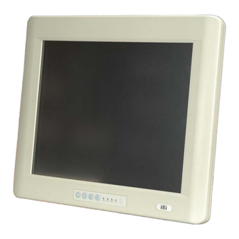
1.1 General Overview Figure 1-1: POC-3174B-A330 Medical Panel PC The POC-3174B-A330 is Intel® Pentium® M powered flat panel PCs with a rich variety of functions and peripherals. The POC-3174B-A330 is designed for easy and simplified integration in to medical applications. -
Page 19: Features And Model Variation
1.2.1 Front Panel The front side of the POC-3174B-A330 is a flat panel 17” TFT LCD screen surrounded by an ABS/PC plastic frame with five Poly Dome buttons and one LED indicator. The functions of the buttons and indicators are described in Figure 1-2. -
Page 20: Figure 1-2: Front View
POC-3174B-A330 Medical Panel PC Figure 1-2: Front View This button activates the LCD display. The embedded LCD ON/OFF Switch computing main board is powered on or off using a reset switch at the bottom of the unit. Green: LCD is on and system is powered on... -
Page 21: Rear Panel
100 mm x 100 mm or a 75 mm x 75 mm VESA standard wall mount or desktop stand. See Figure 1-3. Figure 1-3: Rear View 1.2.3 Bottom Panel The bottom panel of the POC-3174B-A330 has the following I/O interfaces (Figure 1-4): 1 x AT/ATX mode switch Page 5... -
Page 22: Side Panel
POC-3174B-A330 Medical Panel PC 2 x Audio jacks 1 x Clear CMOS button 1 x CompactFlash® slot 1 x DVI connector 1 x PCI add-on card slot 1 x Power input connector 1 x Power switch 2 x PS/2 keyboard/mouse connectors... -
Page 23: Specifications
1 x Power supply 2 x Speakers The technical specifications for the system, and some of these components, are shown in the sections below. 1.3.2 System Specifications The technical specifications for the POC-3174B-A330 systems are listed in Table 1-2. Page 7... - Page 24 POC-3174B-A330 Medical Panel PC SPECIFICATION POC-3174B-A330 LCD Size 17” Max Resolution 1280 x 1024 Brightness (cd/m Contrast Ratio 500:1 LCD Color 16.2M Pixel Pitch (mm) 0.264 (H) x 0.264 (V) Viewing Angle (H-V) 140 / 130 Backlight MTBF 50,000 hours...
-
Page 25: Table 1-2: System Specifications
POC-3174B-A330 Medical Panel PC SPECIFICATION POC-3174B-A330 Drive Bay 1 x slim type CD/DVD drive bay Speakers 2 x 3 W AMP Expansion 1 x PCIe Mini Wireless LAN Module 1 x PCIe slot for an PCI/PCIe add-on card 1 x ExpressCard/54 slot ®... -
Page 26: Specifications
POC-3174B-A330 Medical Panel PC Chapter Specifications Page 10... -
Page 27: Dimensions
POC-3174B-A330 Medical Panel PC 2.1 Dimensions The dimensions of the POC-3174B-A330 medical panel PC are shown in Figure 2-1 below. Figure 2-1: POC-3174B-A330 Dimensions (units in mm) Page 11... -
Page 28: Intel® Processor Support
POC-3174B-A330 Medical Panel PC 2.2 Intel® Processor Support The POC-3174B-A330 is installed with an Intel® Pentium® M 760 processor. The Intel® Pentium® M 760 processor has a CPU speed of 2.0 GHz, a 533 MHz front side bus (FSB) and a 2.0 MB L2 cache. Intel® Pentium® M processor supports the following Intel®... -
Page 29: Additional Memory
IEI sales representative and discuss the necessary system requirement. 2.3.2 Storage Capacity The POC-3174B-A330 is preinstalled with a 2.5” 80 GB SATA hard disk drive. An easy-access slim combo CD/DVD-ROM is mounted on the right side panel and is protected with a cover. -
Page 30: Lan Connectivity
Figure 2-3: COM Ports 2.4.2 LAN Connectivity The POC-3174B-A330 has two GbE connectors on the bottom panel. The PCIe lane from the Intel® ICH6 chipset of the POC-3174B-A330 is interfaced to two PCIe gigabit Ethernet (GbE) controllers, Realtek RTL8111CP GbE controllers. The GbE controllers are then connected directly to the RJ-45 connectors on the bottom panel and provide external GbE connectivity. -
Page 31: Lan Connector For Remote Control
Figure 2-5: RJ-45 Remote Control Connector 2.4.4 External USB Connectors There are two USB 2.0 connectors on the bottom panel of the POC-3174B-A330. All the USB 2.0 connectors are interfaced directly to the USB controllers on the ICH6 Southbridge. The USB connectors are all fully compliant with USB specification Revision 2.0 and USB specification Revision 1.1 and can be interfaced to both USB 1.1 and USB... -
Page 32: Poc-3174B-A330 Front Side
Figure 2-6: External USB Ports 2.5 POC-3174B-A330 Front Side 2.5.1 Monitor A LCD screen is installed on the front of the POC-3174B-A330 and connected to the LVDS connector on the motherboard. The screen is shown in Figure 2-7 below. Figure 2-7: LCD Screen... -
Page 33: Touch-Screen Module
Figure 2-8: VGA and DVI Connectors 2.6.2 Dual-Display The system supports dual display capabilities. An additional monitor can be connected to the POC-3174B-A330 through the VGA connector or DVI connector described above. 2.7 Audio 2.7.1 High Definition Audio Controller The integrated High Definition Audio compliant audio controller on the Intel® ICH6 Southbridge is integrated to a RealTek ALC888 audio codec. -
Page 34: Stereo Speakers
DACs channels and two stereo ADCs. The audio connectors are shown in Figure 2-9. Figure 2-9: Audio Jacks 2.7.2 Stereo Speakers Two stereo speakers on the bottom of the POC-3174B-A330 are interfaced to the system through dual 3 W output amplifier. Figure 2-10: Stereo Speakers 2.8 System Power... -
Page 35: Power Connector
Figure 2-11: Power Connector 2.8.3 Lithium Battery A 3800mAh Lithium Battery Pack is preinstalled in the POC-3174B-A330 series to provide backup power for the system. Before using the battery function, make sure the battery is connected to the system (refer to Section 4.5). Once the battery is connected to the system, the battery starts discharging even when the system power is off. -
Page 36: Power Mode
The system can be run in the AT power mode or the ATX power mode. The power mode switch is shown in Figure 2-13. Figure 2-13: AT/ATX Mode Switch The POC-3174B-A330 is also has an UPS/Battery mode switch shown in Figure 2-14. Page 20... -
Page 37: Figure 2-14: Ups/Battery Mode Switch
POC-3174B-A330 Medical Panel PC Figure 2-14: UPS/Battery Mode Switch Page 21... -
Page 38: Power On/Off
POC-3174B-A330 Medical Panel PC 2.8.5 Power On/Off UPS Mode Battery Mode Battery Only NOT able to turn on by the Battery Only NOT able to turn on by the AT Mode power button. power button. Battery + Turn on automatically when... -
Page 39: Wireless Ethernet Connections
2.9 Wireless Ethernet Connections An integrated 802.11 a/b/g/n wireless LAN module and PIFA antennas on the POC-3174B-A330 ensure an uninterrupted wireless connection. PIFA antennas can receive high-quality, uniform signals in any location from all directions without any signal degradation or impedance and are the most efficient antennas on the market. -
Page 40: Unpacking
POC-3174B-A330 Medical Panel PC Chapter Unpacking Page 24... -
Page 41: Npacking
POC-3174B-A330 Medical Panel PC 3.1 Unpacking To unpack the flat panel PC, follow the steps below: WARNING! The front side LCD screen has a protective plastic cover stuck to the screen. Only remove the plastic cover after the flat panel PC has been properly installed. -
Page 42: Packing List
POC-3174B-A330 Medical Panel PC 3.1.1 Packing List The POC-3174B-A330 medical panel PC is shipped with the following components: Quantity Item Image Standard POC-3174B-A330 medical panel PC Power cord (Europe standard) Medical grade power adapter Screw kit Touch pen User manual CD and driver CD If any of these items are missing or damaged, contact the distributor or sales representative immediately. -
Page 43: Installation
POC-3174B-A330 Medical Panel PC Chapter Installation Page 27... -
Page 44: Anti-Static Precautions
POC-3174B-A330 and severe injury to the user. Electrostatic discharge (ESD) can cause serious damage to electronic components, including the POC-3174B-A330. Dry climates are especially susceptible to ESD. It is therefore critical that whenever the POC-3174B-A330 is accessed internally, or any other... -
Page 45: Installation And Configuration Steps
4.4 Plastic Back Cover Removal WARNING! Take antistatic precautions when working with internal components. The interior of the POC-3174B-A330 contains very sensitive electronic components. These components are easily damaged by electrostatic discharge (ESD). Before working with the internal components make sure all the anti-static precautions described earlier have been observed. -
Page 46: Connect The Battery
Figure 4-1: Back Cover Retention Screws 4.5 Connect the Battery The POC-3174B-A330 panel PC is preinstalled with a Li-on battery. To start using the battery for backup power, the battery connector must be connected. To connect the battery, follow the steps below. -
Page 47: Pci Expansion Card Installation
Figure 4-2: Connect the Battery 4.6 PCI Expansion Card Installation The POC-3174B-A330 has one slot on the bottom panel for PCI card expansion. To install the PCI card, follow the instructions below. Remove the plastic back cover. See Section 4.4. -
Page 48: Cf Card Installation
Step 0: 4.7 CF Card Installation The POC-3174B-A330 has one CompactFlash® Type II slot on the bottom panel. To install the CF card, follow the instructions below. Remove the two CF slot cover retention screws (Figure 4-4) and remove the Step 1: cover off the flat panel PC. -
Page 49: At/Atx Mode Selection
Figure 4-5: CF Card Installation 4.8 AT/ATX Mode Selection AT and ATX power modes can both be used on the POC-3174B-A330. The selection is made through an AT/ATX switch on the bottom panel (Figure 4-6). To select AT mode or ATX mode, follow the steps below. -
Page 50: Mounting The System
PC does not fall down and get damaged. The four methods of mounting the POC-3174B-A330 are listed below. Wall mounting... -
Page 51: Figure 4-7: Wall-Mounting Bracket
POC-3174B-A330 Medical Panel PC Align the wall-mounting bracket screw holes with the pilot holes. Step 4: Secure the mounting-bracket to the wall by inserting the retention screws into Step 5: the four pilot holes and tightening them (Figure 4-7). Figure 4-7: Wall-mounting Bracket... -
Page 52: Figure 4-8: Chassis Support Screws
POC-3174B-A330 Medical Panel PC Figure 4-8: Chassis Support Screws NOTE: In the diagram below the bracket is already installed on the wall. Secure the panel PC by fastening the retention screw of the wall-mounting Step 9: bracket. (Figure 4-9).Step 0:... -
Page 53: Arm Mounting
Figure 4-9: Secure the Panel PC 4.9.2 Arm Mounting The POC-3174B-A330 is VESA (Video Electronics Standards Association) compliant and can be mounted on an arm with a 75 mm or 100 mm interface pad. To mount the POC-3174B-A330 on an arm, please follow the steps below. -
Page 54: Bottom Panel Connectors
4.10 Bottom Panel Connectors All the external peripheral interface connectors are located at the bottom of the rear panel on the POC-3174B-A330 medical panel PC. 4.10.1 Audio Connection Audio signals are interfaced through three phone jack connections. The pink phone jack is for Mic In and green is for Speaker Out. -
Page 55: Dvi Display Device Connection
Figure 4-11: Audio Connectors 4.10.2 DVI Display Device Connection The POC-3174B-A330 has a single female DVI-I connector on the bottom panel. The DVI-I connector is connected to a digital display device. To connect a digital display device to the POC-3174B-A330, please follow the instructions below. -
Page 56: Lan Connection
Locate the RJ-45 connectors on the bottom panel of the POC-3174B-A330. Step 1: Align the connectors. Align the RJ-45 connector on the LAN cable with one of Step 2: the RJ-45 connectors on the bottom panel of the POC-3174B-A330. See Figure 4-13. Page 40... -
Page 57: Ps/2 Keyboard And Mouse Connection
Step 0: 4.10.4 PS/2 Keyboard and Mouse Connection The POC-3174B-A330 has a dual PS/2 connector on the external peripheral interface panel. The dual PS/2 connector is used to connect to a keyboard and mouse to the system. Follow the steps below to connect a keyboard and mouse to the POC-3174B-A330. -
Page 58: Serial Device Connection
POC-3174B-A330 Medical Panel PC Figure 4-14: PS/2 Keyboard/Mouse Connector 4.10.5 Serial Device Connection The POC-3174B-A330 has three single female DB-9 connectors on the bottom panel for a serial device. Follow the steps below to connect a serial device to the POC-3174B-A330 panel PC. -
Page 59: Usb Device Connection
4.10.6 USB Device Connection There are two external USB 2.0 connectors. All connectors are perpendicular to the POC-3174B-A330. To connect a USB 2.0 or USB 1.1 device, please follow the instructions below. Locate the USB connectors. The locations of the USB connectors are shown Step 1: in Chapter 2. -
Page 60: Vga Monitor Connection
Step 0: 4.10.7 VGA Monitor Connection The POC-3174B-A330 has a single female DB-15 connector on the external peripheral interface panel. The DB-15 connector is connected to a CRT or VGA monitor. To connect a monitor to the POC-3174B-A330, please follow the instructions below. -
Page 61: Figure 4-17: Vga Connector
POC-3174B-A330 Medical Panel PC Once the connectors are properly aligned with the Step 3: Insert the VGA connector. insert the male connector from the VGA screen into the female connector on the POC-3174B-A330. See Figure 4-17. Figure 4-17: VGA Connector Secure the connector. -
Page 62: System Maintenance
POC-3174B-A330 Medical Panel PC Chapter System Maintenance Page 46... -
Page 63: Introduction
POC-3174B-A330 Medical Panel PC 5.1 Introduction If the components of the POC-3174B-A330 fail they must be replaced, such as the wireless LAN module or the HDD. Please contact the system reseller or vendor to purchase the replacement parts. Back cover removal instructions and jumper settings for the POC-3174B-A330 are described below. -
Page 64: Figure 5-1: Back Cover Retention Screws
Wireless LAN module CD/DVD-ROM PCI expansion card The back cover of the POC-3174B-A330 must be removed. To remove the back cover, remove the nine retention screws indicated below (Figure 5-1). WARNING! Watch out for the three internal PIFA antennas when removing the back cover. -
Page 65: Hdd Replacement
POC-3174B-A330 Medical Panel PC 5.4 HDD Replacement The POC-3174B-A330 medical panel PC is preinstalled with an 80 GB SATA HDD. If the HDD fails, follow the instructions below to replace the HDD. Disconnect the system power cable. Step 1: Remove the back cover. See Section 5.3. -
Page 66: Memory Module Replacement
POC-3174B-A330 Medical Panel PC Figure 5-3: Hard Drive Retention Screws Attach a new hard drive to the aluminum platform. To do this, align the four Step 5: retention screw holes on sides of the hard drive with the screw holes on the platform. -
Page 67: Figure 5-4: Platform Retention Screws
POC-3174B-A330 Medical Panel PC head screws. Remove the five retention screws (Figure 5-4) and lift the elevated platform off the chassis. Figure 5-4: Platform Retention Screws Locate the DDR2 memory module on the motherboard of the medical panel PC Step 5: (Figure 5-5). -
Page 68: Figure 5-6: Ddr2 So-Dimm Module Installation
POC-3174B-A330 Medical Panel PC Remove the DDR2 memory module by pulling both the spring retainer clips Step 6: outward from the socket. Grasp the DDR2 memory module by the edges and carefully pull it out of the Step 7: socket. -
Page 69: Jumper Settings
OPEN a jumper Jumper means removing the plastic clip from a jumper. The jumpers listed below can be setup for POC-3174B-A330. COM port voltage select (J4) CompactFlash® setup (J7) 5.6.1 COM Port Voltage Select (J4) J4 jumper is located on the motherboard as shown in Figure 5-7. -
Page 70: Figure 5-7: Com Port Voltage Select Jumper Location
POC-3174B-A330 Medical Panel PC Figure 5-7: COM Port Voltage Select Jumper Location The COM ports pin-9 signal can be selected as 12 V or 5 V. The COM Port Voltage selection options are shown in Table 5-1. Description Short 1-3... -
Page 71: Compactflash® Setup (J9)
POC-3174B-A330 Medical Panel PC 5.6.2 CompactFlash® Setup (J9) The Master/Slave selection allows the CompactFlash® slot to be setup as either the IDE master or the IDE slave. If no other IDE device is used in the system, then the setting does not need to be changed. -
Page 72: Ami Bios Setup
POC-3174B-A330 Medical Panel PC Chapter AMI BIOS Setup Page 56... -
Page 73: Introduction
POC-3174B-A330 Medical Panel PC 6.1 Introduction A licensed copy of AMI BIOS is preprogrammed into the ROM BIOS. The BIOS setup program allows users to modify the basic system configuration. This chapter describes how to access the BIOS setup program and the configuration options that may be changed. -
Page 74: Getting Help
POC-3174B-A330 Medical Panel PC F1 key General help, only for Status Page Setup Menu and Option Page Setup Menu F2 /F3 key Change color from total 16 colors. F2 to select color forward. F10 key Save all the CMOS changes, only for Main Menu Table 6-1: BIOS Navigation Keys 6.1.3 Getting Help... -
Page 75: Main
POC-3174B-A330 Medical Panel PC 6.2 Main The Main BIOS menu (BIOS Menu 1) appears when the BIOS Setup program is entered. The Main menu gives an overview of the basic system information. BIOS Menu 1: Main System Overview The System Overview lists a brief summary of different system components. The fields in System Overview cannot be changed. -
Page 76: Advanced
POC-3174B-A330 Medical Panel PC The System Overview field also has two user configurable fields: System Time [xx:xx:xx] Use the System Time option to set the system time. Manually enter the hours, minutes and seconds. System Date [xx/xx/xx] Use the System Date option to set the system date. Manually enter the day, month and year. -
Page 77: Cpu Configuration
POC-3174B-A330 Medical Panel PC BIOS Menu 2: Advanced 6.3.1 CPU Configuration Use the CPU Configuration menu (BIOS Menu 3) to view detailed CPU specifications and configure the CPU. BIOS Menu 3: CPU Configuration Page 61... -
Page 78: Ide Configuration
POC-3174B-A330 Medical Panel PC The CPU Configuration menu (BIOS Menu 3) lists the following CPU details: Manufacturer: Lists the name of the CPU manufacturer Frequency: Lists the CPU processing speed FSB Speed: Lists the FSB speed Cache L1: Lists the CPU L1 cache size Cache L2: Lists the CPU L2 cache size 6.3.2 IDE Configuration... -
Page 79: Legacy Ide Channels [Sata Pri., Pata Sec]
POC-3174B-A330 Medical Panel PC compatible mode. In this mode, a SATA channel will replace one of the IDE channels. This mode supports up to 4 storage devices. Configures the on-board ATA/IDE controller to be in Enhanced Enhanced mode. In this mode, IDE channels and SATA channels are separated. -
Page 80: Ide Master, Ide Slave
POC-3174B-A330 Medical Panel PC 6.3.2.1 IDE Master, IDE Slave Use the IDE Master and IDE Slave configuration menu to view both primary and secondary IDE device details and configure the IDE devices connected to the system. BIOS Menu 5: IDE Master and IDE Slave Configuration... -
Page 81: Zip
POC-3174B-A330 Medical Panel PC specified channel. The CD/DVD option specifies that an IDE CD-ROM CD/DVD drive is attached to the specified IDE channel. The BIOS does not attempt to search for other types of IDE disk drives on the specified channel. -
Page 82: Pio Mode [Auto]
POC-3174B-A330 Medical Panel PC one sector at a time. BIOS auto detects Multi-Sector Transfer support on the Auto EFAULT drive on the specified channel. If supported the data transfer to and from the device occurs multiple sectors at a time. - Page 83 POC-3174B-A330 Medical Panel PC Single Word DMA mode 0 selected with a maximum data SWDMA0 transfer rate of 2.1MBps Single Word DMA mode 1 selected with a maximum data SWDMA1 transfer rate of 4.2MBps Single Word DMA mode 2 selected with a maximum data SWDMA2 transfer rate of 8.3MBps...
-
Page 84: Auto]
POC-3174B-A330 Medical Panel PC rate of 99.9MBps (To use this mode, it is required that an 80-conductor ATA cable is used.) S.M.A.R.T [Auto] Use the S.M.A.R.T option to auto-detect, disable or enable Self-Monitoring Analysis and Reporting Technology (SMART) on the drive on the specified channel. S.M.A.R.T predicts impending drive failures. -
Page 85: Super Io Configuration
POC-3174B-A330 Medical Panel PC 6.3.3 Super IO Configuration Use the Super IO Configuration menu (BIOS Menu 6) to set or change the configurations for the serial ports. BIOS Menu 6: Super IO Configuration Serial Port1 Address [3F8/IRQ4] Use the Serial Port1 Address option to select the Serial Port 1 base address. -
Page 86: Serial Port1 Mode [Normal]
POC-3174B-A330 Medical Panel PC Serial Port1 Mode [Normal] Use the Serial Port1 Mode option to select the transmitting and receiving mode for the first serial port. Serial Port 1 mode is normal Normal EFAULT Serial Port 1 mode is IrDA... -
Page 87: Serial Port3 Address [3E8]
POC-3174B-A330 Medical Panel PC Serial Port3 Address [3E8] Use the Serial Port3 IRQ option to select the interrupt address for serial port 3. No base address is assigned to serial port 3 Disabled Serial port 3 I/O port address is 3F8... -
Page 88: Touch Panel Irq [10]
POC-3174B-A330 Medical Panel PC Serial port 3 I/O port address is 2E8 EFAULT Serial port 3 I/O port address is 2F0 Serial port 3 I/O port address is 2E0 Touch Panel IRQ [10] Use the Touch Panel IRQ option to select the touch panel port interrupt address. -
Page 89: Serial Port6 Address [2E0]
POC-3174B-A330 Medical Panel PC Serial Port6 Address [2E0] Use the Serial Port6 Address option to select the interrupt address for serial port 6. No base address is assigned to serial port 6 Disabled Serial port 6 I/O port address is 3E8... -
Page 90: Hardware Health Configuration
POC-3174B-A330 Medical Panel PC 6.3.4 Hardware Health Configuration The Hardware Health Configuration menu (BIOS Menu 7) shows the operating temperature, fan speeds and system voltages. BIOS Menu 7: Hardware Health Configuration CPU FAN Mode Setting [Automatic mode] Use the CPU FAN Mode Setting option to configure the CPU fan. -
Page 91: Sys Fan Mode Setting [Full On Mode]
POC-3174B-A330 Medical Panel PC SYS FAN Mode Setting [Full On mode] Use the SYS FAN Mode Setting option to configure the second system fan. Fan is on all the time Full On Mode EFAULT Fan is off when the temperature is low Automatic mode enough. -
Page 92: Temp. Limit Of Start
POC-3174B-A330 Medical Panel PC which the cooling fan should automatically turn off. To select a value, select the Temp. Limit of OFF option and enter a decimal number between 000 and 127. The temperature range is specified below. Minimum Value: 0°C Maximum Value: 127°C... -
Page 93: Slope Pwm 1
POC-3174B-A330 Medical Panel PC PWM Minimum Mode: 0 PWM Maximum Mode: 127 Slope PWM 1 The Slope PWM 1 option can only be set if the FAN Mode Setting option is set to Automatic Mode. Use the Slope PWM 1 option to select the linear rate at which the PWM mode increases with respect to an increase in temperature. -
Page 94: Acpi Configuration
POC-3174B-A330 Medical Panel PC GMCH 5VSB VBAT 6.3.5 ACPI Configuration The ACPI Configuration menu (BIOS Menu 8) configures the Advanced Configuration and Power Interface (ACPI) and Power Management (APM) options. BIOS Menu 8: ACPI Configuration Suspend Mode [S1 (POS)] Use the Suspend Mode option to specify the sleep state the system enters when it is not being used. -
Page 95: Remote Access Configuration
POC-3174B-A330 Medical Panel PC Power to the RAM is maintained. The computer returns slower to a working state, but more power is saved. 6.3.6 Remote Access Configuration Use the Remote Access Configuration menu (BIOS Menu 9) to configure remote access parameters. The Remote Access Configuration is an AMIBIOS feature and allows a remote host running a terminal program to display and configure the BIOS settings. -
Page 96: Serial Port Number
POC-3174B-A330 Medical Panel PC Remote access configuration options shown below Enabled appear: Serial Port Number Serial Port Mode Redirection after BIOS POST Terminal Type These configuration options are discussed below. Serial Port Number [COM1] Use the Serial Port Number option to select the serial port used for remote access. -
Page 97: Redirection After Bios Post [Always]
POC-3174B-A330 Medical Panel PC 115200 8,n,1 D EFAULT 57600 8,n,1 38400 8,n,1 19200 8,n,1 09600 8,n,1 NOTE: Identical baud rate setting musts be set on the host (a management computer running a terminal software) and the slave Redirection After BIOS POST [Always] Use the Redirection After BIOS POST option to specify when console redirection should occur. -
Page 98: Usb Configuration
POC-3174B-A330 Medical Panel PC 6.3.7 USB Configuration Use the USB Configuration menu (BIOS Menu 10) to read USB configuration information and configure the USB settings. BIOS Menu 10: USB Configuration USB Functions [Enabled] Use the USB Functions BIOS option to enable or disable USB function support. -
Page 99: Pci/Pnp
POC-3174B-A330 Medical Panel PC Legacy USB Support [Enabled] Use the Legacy USB Support BIOS option to enable USB mouse and USB keyboard support. Normally if this option is not enabled, any attached USB mouse or USB keyboard does not become available until a USB compatible operating system is fully booted with all USB drivers loaded. -
Page 100: Menu 11: Pci/Pnp Configuration
POC-3174B-A330 Medical Panel PC BIOS Menu 11: PCI/PnP Configuration IRQ# [Available] Use the IRQ# address to specify what IRQs can be assigned to a particular peripheral device. The specified IRQ is available to be used by Available EFAULT PCI/PnP devices... -
Page 101: Dma Channel# [Available]
POC-3174B-A330 Medical Panel PC IRQ 11 IRQ 14 IRQ 15 DMA Channel# [Available] Use the DMA Channel# option to assign a specific DMA channel to a particular PCI/PnP device. The specified DMA is available to be used by Available EFAULT... -
Page 102: Boot
POC-3174B-A330 Medical Panel PC 6.5 Boot Use the Boot menu (BIOS Menu 12) to configure system boot options. BIOS Menu 12: Boot Page 86... -
Page 103: Boot Settings Configuration
POC-3174B-A330 Medical Panel PC 6.5.1 Boot Settings Configuration Use the Boot Settings Configuration menu (BIOS Menu 13) to configure advanced system boot options. BIOS Menu 13: Boot Settings Configuration Quick Boot [Enabled] Use the Quick Boot BIOS option to make the computer speed up the boot process. -
Page 104: Addon Rom Display Mode [Force Bios]
POC-3174B-A330 Medical Panel PC AddOn ROM Display Mode [Force BIOS] The AddOn ROM Display Mode option allows add-on ROM (read-only memory) messages to be displayed. Allows the computer system to force a third party Force BIOS EFAULT BIOS to display during system boot. -
Page 105: Boot Device Priority
POC-3174B-A330 Medical Panel PC Can be booted from a remote system through the Enabled 6.5.2 Boot Device Priority Use the Boot Device Priority menu to specify the boot sequence from the available devices. Possible boot devices may include: CD/DVD 6.5.3 Hard Disk Drives Use the Hard Disk Drives menu to specify the boot sequence of the available HDDs. -
Page 106: Security
POC-3174B-A330 Medical Panel PC NOTE: Only the drives connected to the system are shown. For example, if only two CDs or DVDs are connected only “1st Drive” and “2nd Drive” are listed. The boot sequence from the available devices is selected. If the “1st Drive” option is selected a list of available CD/DVD drives is shown. -
Page 107: Chipset
POC-3174B-A330 Medical Panel PC this field and enter the password. After the password has been added, Install appears next to Change Supervisor Password. Change User Password Use the Change User Password to set or change a user password. The default for this option is Not Installed. -
Page 108: North Bridge Configuration
POC-3174B-A330 Medical Panel PC 6.7.1 North Bridge Configuration Use the North Bridge Configuration menu (BIOS Menu 16) to check the Northbridge chipset settings. BIOS Menu 16:North Bridge Chipset Configuration Memory Hole [Disabled] Use the Memory Hole option to reserve memory space between 15MB and 16MB for ISA expansion cards that require a specified area of memory to work properly. -
Page 109: Internal Graphics Mode Select [Enable, 8Mb]
POC-3174B-A330 Medical Panel PC Internal Graphics Mode Select [Enable, 8MB] Use the Internal Graphic Mode Select option to specify the amount of system memory that can be used by the Internal graphics device. Disable 1MB of memory used by internal graphics device... -
Page 110: South Bridge Configuration
POC-3174B-A330 Medical Panel PC 6.7.2 South Bridge Configuration The South Bridge Configuration menu (BIOS Menu 17) enables the Southbridge chipset to be configured. BIOS Menu 17:South Bridge Chipset Configuration Spread Spectrum Function [Disabled] Use the Spread Spectrum Function option to reduce the EMI. Excess EMI is generated when the system clock generator pulses have extreme values. -
Page 111: Power Configuration
POC-3174B-A330 Medical Panel PC 6.7.3 Power Configuration The Power Configuration menu (BIOS Menu 18) allows the advanced power management options to be configured. BIOS Menu 18: Power Configuration Page 95... -
Page 112: Advanced Power Configuration
POC-3174B-A330 Medical Panel PC 6.7.4 Advanced Power Configuration The Advanced Power Configuration menu (BIOS Menu 18) allows the advanced power management options to be configured. BIOS Menu 19: Advanced Power Configuration Power Button Mode [On/Off] Use the Power Button Mode BIOS to specify how the power button functions. -
Page 113: Rtc Alarm Date (Days)
POC-3174B-A330 Medical Panel PC The real time clock (RTC) cannot generate a wake Disabled EFAULT event If selected, the following appears with values that Enabled can be selected: RTC Alarm Date (Days) RTC Alarm Time After setting the alarm, the computer turns itself on from a suspend state when the alarm goes off. -
Page 114: Keyboard/Mouse Resume [Disabled]
POC-3174B-A330 Medical Panel PC Keyboard/Mouse Resume [Disabled] Use the Keyboard/Mouse Resume BIOS option to enable activity on either the keyboard or mouse to rouse the system from a suspend or standby state. That is, the system is roused when the mouse is moved or a button on the keyboard is pressed. -
Page 115: Exit
POC-3174B-A330 Medical Panel PC 6.8 Exit Use the Exit menu (BIOS Menu 20) to load default BIOS values, optimal failsafe values and to save configuration changes. BIOS Menu 20:Exit Save Changes and Exit Use the Save Changes and Exit option to save the changes made to the BIOS options and to exit the BIOS configuration setup program. -
Page 116: Load Optimal Defaults
POC-3174B-A330 Medical Panel PC Load Optimal Defaults Use the Load Optimal Defaults option to load the optimal default values for each of the parameters on the Setup menus. F9 key can be used for this operation. Load Failsafe Defaults Use the Load Failsafe Defaults option to load failsafe default values for each of the parameters on the Setup menus. -
Page 117: Software Drivers
POC-3174B-A330 Medical Panel PC Chapter Software Drivers Page 101... -
Page 118: Available Software Drivers
POC-3174B-A330 Medical Panel PC 7.1 Available Software Drivers NOTE: The content of the CD may vary throughout the life cycle of the product and is subject to change without prior notice. Visit the IEI website or contact technical support for the latest updates. -
Page 119: Figure 7-1: Intel® Package Manager
POC-3174B-A330 Medical Panel PC Figure 7-1: Intel® Package Manager The Intel® Setup Welcome screen. See Figure 7-2. Step 3: Figure 7-2: Intel® Setup Welcome Screen Click N to continue. Step 4: The Intel® license agreement in appears. Step 5: Page 103... -
Page 120: Figure 7-3: Intel® Chipset Driver License Agreement
POC-3174B-A330 Medical Panel PC Figure 7-3: Intel® Chipset Driver License Agreement Accept the terms and conditions by clicking Y Step 6: The Readme file in Figure 7-4 appears. Step 7: Figure 7-4: Readme File Click N to continue. Step 8:... -
Page 121: Intel® Graphics Media Accelerator Driver
POC-3174B-A330 Medical Panel PC The driver is then installed. Step 9: When the installation process is complete, the Setup Complete screen appears. Step 10: See Figure 7-5. Figure 7-5: Intel® Chipset Driver Complete Installation Screen To complete the chipset driver installation, click F... -
Page 122: Figure 7-6: Gma Driver Readme File
POC-3174B-A330 Medical Panel PC Figure 7-6: GMA Driver Readme File Click N to extract the GMA driver files. See Figure 7-7. Step 3: Figure 7-7: GMA Driver File Extraction The welcome screen shown in Figure 7-8 appears. Step 4: Page 106... -
Page 123: Figure 7-8: Gma Driver Installation Welcome Screen
POC-3174B-A330 Medical Panel PC Figure 7-8: GMA Driver Installation Welcome Screen To continue the installation process, click N Step 5: The license agreement in Figure 7-9 appears. Step 6: Figure 7-9: GMA Driver License Agreement Click the Y in Figure 7-9 to continue. -
Page 124: Realtek Rtl8111Cp Gbe Lan Installation
POC-3174B-A330 Medical Panel PC The installation notice shown in Figure 7-10 appears. Step 8: Figure 7-10: GMA Driver Installing Notice A confirmation screen shown in Figure 7-11 appears. Step 9: Figure 7-11: GMA Driver Installation Complete After selecting when to restart the computer in Figure 7-11, click F... -
Page 125: Figure 7-12: Rtl8111Cp Installshield Wizard
POC-3174B-A330 Medical Panel PC The InstallShield Wizard is prepared to guide the user through the rest of the Step 2: process (Figure 7-12). Figure 7-12: RTL8111CP InstallShield Wizard The InstallShield Wizard continues (Figure 7-13). Step 3: Figure 7-13: RTL8111CP InstallShield Wizard Continues... -
Page 126: Figure 7-14: Rtl8111Cp Installshield Wizard Welcome Screen
POC-3174B-A330 Medical Panel PC Figure 7-14: RTL8111CP InstallShield Wizard Welcome Screen Click N to continue the installation. Step 5: The InstallShield Wizard is ready to install the driver (Figure 7-15). Step 6: Figure 7-15: RTL8111CP Driver Ready Screen Click I to continue the installation process. -
Page 127: Figure 7-16: Rtl8111Cp Drivers Installing
POC-3174B-A330 Medical Panel PC Figure 7-16: RTL8111CP Drivers Installing The InstallShield Wizard continues (Figure 7-17). Step 9: Figure 7-17: RTL8111CP InstallShield Wizard After the driver installation process is complete, a confirmation screen appears Step 10: (Figure 7-18). Page 111... -
Page 128: Realtek Hd Audio Driver Installation
POC-3174B-A330 Medical Panel PC Figure 7-18: RTL8111CP Driver Installation Complete Click F to exit the program. Step 11: Step 0: INISH 7.5 Realtek HD Audio Driver Installation To install the Realtek High Definition (HD) Audio driver, please follow the steps below. -
Page 129: Figure 7-19: The Installshield Wizard Starts
POC-3174B-A330 Medical Panel PC Insert the driver CD into the system. Open the x:\Audio\WDM_R204 directory Step 1: and locate the icon for the Setup.exe installation file. Once located, use the mouse to double click the icon. The InstallShield Wizard starts (Figure 7-19). -
Page 130: Figure 7-21: Installshield Wizard Welcome Screen
POC-3174B-A330 Medical Panel PC Figure 7-21: InstallShield Wizard Welcome Screen Click N to continue the installation. Step 5: InstallShield starts to install the new software as shown in Figure 7-22. Step 6: Figure 7-22: Audio Driver Software Configuration The Installation Wizard updates the system as shown in Figure 7-23. -
Page 131: Figure 7-23: Installation Wizard Updates The System
POC-3174B-A330 Medical Panel PC Figure 7-23: Installation Wizard Updates the System After the driver installation process is complete, a confirmation screen appears Step 8: (Figure 7-24). Figure 7-24: Restart the Computer Page 115... -
Page 132: Touch Screen Driver
POC-3174B-A330 Medical Panel PC The confirmation screen offers the option of restarting the computer now or later. Step 9: For the settings to take effect, the computer must be restarted. Click F INISH restart the computer. Step 0: 7.6 Touch Screen Driver To install the touch panel software driver, please follow the steps below. -
Page 133: Figure 7-26: License Agreement
POC-3174B-A330 Medical Panel PC Figure 7-26: License Agreement Click N and the Installshield Wizard is ready to install the program (Figure Step 4: 7-27). Figure 7-27: Ready to Install the Program Click I to continue. The Installing PenMount DMC9000 screen appears... -
Page 134: Wireless Lan Driver
POC-3174B-A330 Medical Panel PC Figure 7-28: Installing PenMount DMC9000 The user is then prompted to select to restart the computer now or later (Figure Step 6: 7-29). For the settings to take effect, the computer must be restarted. Click Yes to restart the computer. -
Page 135: Figure 7-30: Windows Control Panel
POC-3174B-A330 Medical Panel PC Figure 7-30: Windows Control Panel Double-click the System icon (Figure 7-31). Step 2: Page 119... -
Page 136: Figure 7-31: System Icon
POC-3174B-A330 Medical Panel PC Figure 7-31: System Icon Click the Device Manager tab (Figure 7-32). Step 3: Page 120... -
Page 137: Figure 7-32: Device Manager Tab
POC-3174B-A330 Medical Panel PC Figure 7-32: Device Manager Tab A list of system hardware devices appears (Figure 7-33). Step 4: Page 121... -
Page 138: Figure 7-33: Device Manager List
POC-3174B-A330 Medical Panel PC Figure 7-33: Device Manager List Double-click the listed device that has question marks next to it (this means Step 5: Windows does not recognize the device). The Device Driver Wizard appears (Figure 7-34). Step 6: Page 122... -
Page 139: Figure 7-34: Search For Suitable Driver
POC-3174B-A330 Medical Panel PC Figure 7-34: Search for Suitable Driver Select “Search for a suitable driver for my device (recommended),” and click Step 7: to continue. Select “Specify a Location” in the Locate Driver Files window (Figure 7-35). Step 8:... -
Page 140: Figure 7-36: Location Browsing Window
POC-3174B-A330 Medical Panel PC Figure 7-36: Location Browsing Window Select the proper OS folder under the “X:\LAN\Intel 4965AGN” directory in the Step 11: Locate File window, where “X:\” is the system CD drive. Select a proper operating system folder for wireless LAN driver installation. -
Page 141: Battery Monitoring And Remote Control
POC-3174B-A330 Medical Panel PC Chapter Battery Monitoring and Remote Control Page 125... -
Page 142: Introduction
POC-3174B-A330 Medical Panel PC 8.1 Introduction The IEI AUPS Battery Status Monitor application detects the information of the smart battery and monitors the battery status. It is recommended to execute this AUPS application in Windows XP SP2 environment. 8.2 Monitoring DC Power and Smart Battery 8.2.1 Application Installation... -
Page 143: Figure 8-2: Select Installation Folder
POC-3174B-A330 Medical Panel PC Figure 8-2: Select Installation Folder Click N and the Installshield Wizard is ready to install the program (Figure Step 4: 8-3). Figure 8-3: Ready to Install the Program Click N to continue. The Installing AUPS_Setup screen appears as the Step 5: program is installed (Figure 8-4). -
Page 144: Figure 8-4: Installing Aups
POC-3174B-A330 Medical Panel PC Figure 8-4: Installing AUPS The Installation Complete window appears (Figure 8-5). Click Close to exit. Step 6: Figure 8-5: Installation Complete To launch the application, double click the shortcut (Figure 8-6) on the desktop. Step 7:... -
Page 145: Status Information
POC-3174B-A330 Medical Panel PC 8.2.2 Status Information The IEI AUPS Battery Status Monitor application shows the DC power status and battery status (Figure 8-7). The following sections describe the status information in details. Figure 8-7: Status Information 8.2.2.1 DC Detection When the DC power is connected to the AUPS series power module, the AUPS Battery Status Monitor detects it and shows in the screen as Figure 8-8. -
Page 146: Battery Detection
POC-3174B-A330 Medical Panel PC 8.2.2.2 Battery Detection When the smart battery is connected to the AUPS series power module, the AUPS Battery Status Monitor detects it and shows in the screen as Figure 8-9. Two batteries can be connected to the AUPS series power module at the same time. The second battery information is shown in the Battery A Detection section if connected. -
Page 147: Total Battery Time
POC-3174B-A330 Medical Panel PC 8.2.2.3 Total Battery Time The total battery time is shown in the top right corner (Figure 8-10) of the status screen to indicate the total battery remaining time. Figure 8-10: Total Battery Time 8.2.3 Battery Information Click on the BAT. -
Page 148: Lan Setting
POC-3174B-A330 Medical Panel PC 8.2.4 LAN Setting The LAN Setting page is where to configure the Remote LAN settings for power on/off remote control and battery monitoring. To save the modified parameters of this page, click button. To load the default settings, click button. -
Page 149: Setting
POC-3174B-A330 Medical Panel PC Figure 8-13: LAN Setting – Change Password 8.2.5 Setting Click on the SETTING tab to select the COM port, enable/disable buzzer, LAN and DC output (Figure 8-14). Page 133... -
Page 150: Figure 8-14: Application Setting
COM port (COM1~COM16) and shows the valid COM port. Figure 8-15 shows the AUPS application is communicating with POC-3174B-A330 through COM 6. To change the serial port to communicate, select a proper port number from the list and click Connect. Before changing, please make sure the selected serial port is not used by other devices. -
Page 151: Remote Control And Monitoring
8.3 Remote Control and Monitoring The POC-3174B-A330 can be controlled (power on/off) and monitored the battery status through a remote computer located in the same subnet with the POC-3174B-A330. To control and monitor the POC-3174B-A330 remotely, follow the steps below. -
Page 152: Figure 8-17: Iei Remote Ap
Step 3: panel PCs in the same subnet with this remote computer are shown in the list on the right. Click the function buttons on the left to control the POC-3174B-A330. Figure 8-17: IEI REMOTE AP To access the web interface for advanced monitoring and functions, double click Step 4: the IP address of the connected POC-3174B-A330 (Figure 8-18). -
Page 153: Figure 8-18: Iei Remote Ap - Ip Address
POC-3174B-A330 Medical Panel PC Figure 8-18: IEI REMOTE AP – IP Address Figure 8-19 shows in a web browser. Step 5: Figure 8-19: Remote Management Web Interface - Status To send an email to an administrator through the SMTP server, click Send Step 6: E-mail button on the left. -
Page 154: Figure 8-20: Remote Management Web Interface - Send Email
POC-3174B-A330 Medical Panel PC Figure 8-20: Remote Management Web Interface - Send Email To configure the POC-3174B-A330 network setting, click the Configuration Step 7: button on the left. A window prompts for the user name and password. The default user name and... -
Page 155: Figure 8-22: Board Configuration
POC-3174B-A330 Medical Panel PC The Board Configuration window appears. Configure the network settings and Step 9: click the Save Config button. Incorrect settings may cause the board to lose network connectivity. Recovery options are provided on the next page. Step 0:... -
Page 156: System Specifications
POC-3174B-A330 Medical Panel PC Appendix System Specifications Page 140... -
Page 157: Motherboard Specifications
POC-3174B-A330 Medical Panel PC A.1 Motherboard Specifications The POC-3174B-A330 comes with an A330 motherboard pre-installed. The technical specifications of the motherboard are listed in Table 8-1. Specification A330 2.0 GHz Intel® Pentium® M processor 760 System Chipset Intel® 915GME + ICH6... -
Page 158: Flat Panel Screen Specifications
POC-3174B-A330 Medical Panel PC A.2 Flat Panel Screen Specifications The POC-3174B-A330 comes with a TFT LCD monitor at the front of the flat panel PC. The specifications for the LCD monitor are shown in Table 8-2 below. SPECIFICATION 17 inch Active Area (H x V) (mm) 337.9 x 270.3... -
Page 159: Power Adapter
20%~90 %RH. Table 8-3: Touch Panel Specifications A.4 Power Adapter The POC-3174B-A330 comes with a MPU-100-105 100 W medical grade switching power adapter. The specifications of the power adapter are listed in Table 8-4. Voltage 90 ~ 264 V AC Full Range... -
Page 160: Battery Specifications
89.5 mm (W) x 45.5 mm (H) x 188.9 mm (D) Table 8-4: Power Supply Specifications A.5 Battery Specifications The POC-3174B-A330 series come with a Lithium-ion battery. Some of the Lithium-ion battery specifications are listed in Table 8-5. Model Name... -
Page 161: Wireless Lan Module
POC-3174B-A330 Medical Panel PC A.6 Wireless LAN Module The IEEE 802.11a/b/g/n compliant Intel® wireless Wi-Fi Link 4965AGN module is pre-installed in the system and provides wireless connectivity at up to 300 Mbps. The wireless module is interfaced to the system chipset through the PCIe Mini slot. -
Page 162: Bsafety Precautions
POC-3174B-A330 Medical Panel PC Appendix Safety Precautions Page 146... -
Page 163: Safety Precautions
Do not apply voltage levels that exceed the specified voltage range. Doing so may cause fire and/or an electrical shock. Electric shocks can occur if the POC-3174B-A330 chassis is opened when the POC-3174B-A330 is running. Do not drop or insert any objects into the ventilation openings of the POC-3174B-A330. -
Page 164: Explanation Of Graphical Symbols
IEC standards (e.g. IEC 60950 for data processing equipment and IEC 60601-1 for medical equipment). DO NOT: Drop the POC-3174B-A330 against a hard surface. Strike or exert excessive force onto the LCD panel. Touch any of the LCD panels with a sharp object In a site where the ambient temperature exceeds the rated temperature B.1.2 Explanation of Graphical Symbols... -
Page 165: Anti-Static Precautions
Electrostatic discharge (ESD) can cause serious damage to electronic components, including the POC-3174B-A330. Dry climates are especially susceptible to ESD. It is therefore critical that whenever the POC-3174B-A330 is opened and any of the electrical components are handled, the following anti-static precautions are strictly adhered to. -
Page 166: Maintenance And Cleaning Precautions
When maintaining or cleaning the POC-3174B-A330, please follow the guidelines below. B.2.1 Maintenance and Cleaning Prior to cleaning any part or component of the POC-3174B-A330, please read the details below. During normal use of the POC-3174B-A330 may become soiled and should, therefore, be cleaned regularly every month. -
Page 167: Cleaning Tools
In such case, the product will be explicitly mentioned in the cleaning tips. Below is a list of items to use when cleaning the POC-3174B-A330. C loth – Although paper towels or tissues can be used, a soft, clean piece of cloth is recommended when cleaning the POC-3174B-A330. -
Page 168: Cbios Configuration Options
POC-3174B-A330 Medical Panel PC Appendix BIOS Configuration Options Page 152... -
Page 169: C.1 Bios C Onfiguration O Ptions
POC-3174B-A330 Medical Panel PC C.1 BIOS Configuration Options Below is a list of BIOS configuration options described in Chapter 6. Menu 1: Main System Overview ....................59 System Time [xx:xx:xx] ..................60 System Date [xx/xx/xx] ..................60 Menu 2: Advanced.......................61 Menu 3: CPU Configuration ..................61... - Page 170 POC-3174B-A330 Medical Panel PC Touch Panel Address [2E8] ..................71 Touch Panel IRQ [10].....................72 Serial Port5 Address [2F0]..................72 Serial Port5 IRQ [10] ....................72 Serial Port6 Address [2E0]..................73 Serial Port6 IRQ [10] ....................73 Menu 7: Hardware Health Configuration ..............74 ...
- Page 171 POC-3174B-A330 Medical Panel PC IRQ# [Available]....................84 DMA Channel# [Available] ..................85 Menu 12: Boot......................86 Menu 13: Boot Settings Configuration..............87 Quick Boot [Enabled] ....................87 Quiet Boot [Enabled] .....................87 AddOn ROM Display Mode [Force BIOS] ............88 Bootup Num-Lock [On] ..................88 ...
- Page 172 POC-3174B-A330 Medical Panel PC Discard Changes and Exit ..................99 Discard Changes....................99 Load Optimal Defaults..................100 Load Failsafe Defaults..................100 Page 156...
-
Page 173: Dwatchdog Timer
POC-3174B-A330 Medical Panel PC Appendix Watchdog Timer Page 157... - Page 174 POC-3174B-A330 Medical Panel PC NOTE: The following discussion applies to DOS environment. IEI support is contacted or the IEI website visited for specific drivers for more sophisticated operating systems, e.g., Windows and Linux. The Watchdog Timer is provided to ensure that standalone systems can always recover from catastrophic conditions that cause the CPU to crash.
-
Page 175: Example Program
POC-3174B-A330 Medical Panel PC NOTE: When exiting a program it is necessary to disable the Watchdog Timer, otherwise the system resets. Example program: ; INITIAL TIMER PERIOD COUNTER W_LOOP: AX, 6F02H ;setting the time-out value BX, 05 ;time-out value is 5 seconds ;... -
Page 176: Ehazardous Materials Disclosure
POC-3174B-A330 Medical Panel PC Appendix Hazardous Materials Disclosure Page 160... -
Page 177: Hazardous Material Disclosure Table For Ipb Products Certified As Rohs Compliant Under 2002/95/Ec Without Mercury
POC-3174B-A330 Medical Panel PC E.1 Hazardous Material Disclosure Table for IPB Products Certified as RoHS Compliant Under 2002/95/EC Without Mercury The details provided in this appendix are to ensure that the product is compliant with the Peoples Republic of China (China) RoHS standards. The table below acknowledges the presences of small quantities of certain materials in the product, and is applicable to China RoHS only. - Page 178 POC-3174B-A330 Medical Panel PC Part Name Toxic or Hazardous Substances and Elements Lead Mercury Cadmium Hexavalent Polybrominated Polybrominated (Hg) (Cd) Chromium (Pb) Biphenyls Diphenyl Ethers (CR(VI)) (PBB) (PBDE) Housing Display Printed Circuit Board Metal Fasteners Cable Assembly Fan Assembly Power Supply...
- Page 179 POC-3174B-A330 Medical Panel PC 此附件旨在确保本产品符合中国 RoHS 标准。以下表格标示此产品中某有毒物质的含量符 合中国 RoHS 标准规定的限量要求。 本产品上会附有”环境友好使用期限”的标签,此期限是估算这些物质”不会有泄漏或突变”的 年限。本产品可能包含有较短的环境友好使用期限的可替换元件,像是电池或灯管,这些元 件将会单独标示出来。 部件名称 有毒有害物质或元素 铅 汞 镉 六价铬 多溴联苯 多溴二苯醚 (Pb) (Hg) (Cd) (CR(VI)) (PBB) (PBDE) 壳体 显示 印刷电路板 金属螺帽 电缆组装 风扇组装 电力供应组装 电池 O: 表示该有毒有害物质在该部件所有物质材料中的含量均在 SJ/T11363-2006 标准规定的限量要求以下。 X: 表示该有毒有害物质至少在该部件的某一均质材料中的含量超出 SJ/T11363-2006 标准规定的限量要求。...
-
Page 180: International Standards Compliance
POC-3174B-A330 Medical Panel PC Appendix International Standards Compliance Page 164... -
Page 181: Ul 60601-1 And Can/Csa C22.2 No. 601.1
POC-3174B-A330 Medical Panel PC F.1 UL 60601-1 AND CAN/CSA C22.2 NO. 601.1 Authentication sign of Standard Inspection Bureau for U.S.A. Complies with UL 60601-1 AND CAN/CSA C22.2 NO. 601.1. F.2 EN 60601-1 TUV Rheinland Product Safety safety mark for compliance with EN 60601-1. -
Page 182: Standard Inspection Bureau For China
POC-3174B-A330 Medical Panel PC F.5 Standard Inspection Bureau for China Authentication sign of the Standard Inspection Bureau for China. Page 166... - Page 183 POC-3174B-A330 Medical Panel PC Index Page 167...
- Page 184 POC-3174B-A330 Medical Panel PC DVI connector ..........6 A DVI Display Device ........39 connection ..........39 ACPI ............78 DVI-I connector ..........39 anti-static precautions........28 anti-static pad ........28, 149 E anti-static wristband.......28, 149 handling ..........149 electrostatic discharge .......28 self-grounding........28, 149 ExpressCard/54 ........3, 6, 9 Audio device connector ......38...
- Page 185 POC-3174B-A330 Medical Panel PC Touch screen..........7 P parallel port ........71, 72, 73 U PCI slot ............3 USB............. 82, 83 Poly Dome buttons ........3 external USB device connection ...43 Power Button Mode ........96 USB 2.0............82 Power switch..........6 USB connectors ...........6 PS/2 .............6 USB device connection......43...
Need help?
Do you have a question about the POC-3174B-A330 and is the answer not in the manual?
Questions and answers