Marstair CC 875 Technical Manual
Cassette split systems
Hide thumbs
Also See for CC 875:
- Installation instructions manual (13 pages) ,
- Installation instruction (6 pages)
Table of Contents
Advertisement
Quick Links
This manual provides technical and installation information for
ELECTROMECHANICAL CC 875, ELECTRONIC CC 875 L and CC 875 E systems:-
INDOOR UNIT:
MATCHED WITH: 550 series MCU+ Condensing Units (MCUP=MCU+ in Germany)
GENERAL
SELECTION
ELECTRICAL
SOUND LEVELS
UNIT
DIAGRAMS
OPERATING
INSTRUCTIONS
IMAGE 875
KITS
COMPONENT
IDENTIFICATION
FAULT FINDING
TEV Ltd.
Armytage Road, Brighouse,
West Yorkshire. HD6 1QF
Tel: +44 (0) 1484 405600
Fax: +44 (0) 1484 405620
E-mail: sales@marstair.com
Tel: 01823 665660
Heronhill - for all your Marstair requirements
TECHNICAL MANUAL
for ELECTROMECHANICAL CC 875
ELECTRONIC CC 875 L and CC 875 E
CASSETTE SPLIT SYSTEMS
555 series CC 875, CC875 L or CC875 E
551 series MHPUE or MHPUL Heat Pump Units
542 series DCUE Ducted Condensing Units
INDEX
Part Numbers, dimensions and weights
Features/Accessories, unit combinations
Performance data, optional heating, airflows
Discharge velocities, fresh air supply
Branch Duct, discharge blanking
Recommended Fuse Sizes
Sound Pressure/Sound Power Levels
CC 875 unpacking
Dimensions, weights, chassis removal
Pipework, restrictors
Condensate drain
Air outlet blanking, fitting the fascia
MCU+/MHPUE/MHPUL installation
Dcue installation
Electrical Supply and interconnecting options
Cc875 fan speed selection
CC875 L PCBA configuration
Outdoor unit supply wiring, fire link
Remote controller CC 875
CC 875 L
CC 875 E
Evacuating and charging
Additional refrigerant and oil
Check list
CC 875 units
Condensing Units and heat pumps
CC 875
CC 875 L
CC 875 E
Electric heater kits
5m high condensate pump
BMS interface kit
Fresh air inlet
Adjacent room discharge spigot
Remote temperature sensor kit
EMC termination Kit (CC 875 E units only)
Vane Motor Kit
Exploded Views showing components
All units
www.heronhill.co.uk
15
1
PAGE
2 - 3
4
5 - 6
6
7
7 - 9
10
11
12
13
14
16
17
18
19
21
21
22
22
23
23
24
25
26
27
28 - 29
30 - 37
38 - 40
41
42 - 43
44 - 47
48
52
55
56
57
58
59
60 - 61
62 - 65
66 - 68
55508037-07
Fax: 01823 665807
Advertisement
Table of Contents

Related Manuals for Marstair CC 875


Summary of Contents for Marstair CC 875
- Page 1 ELECTRONIC CC 875 L and CC 875 E CASSETTE SPLIT SYSTEMS This manual provides technical and installation information for ELECTROMECHANICAL CC 875, ELECTRONIC CC 875 L and CC 875 E systems:- INDOOR UNIT: 555 series CC 875, CC875 L or CC875 E...
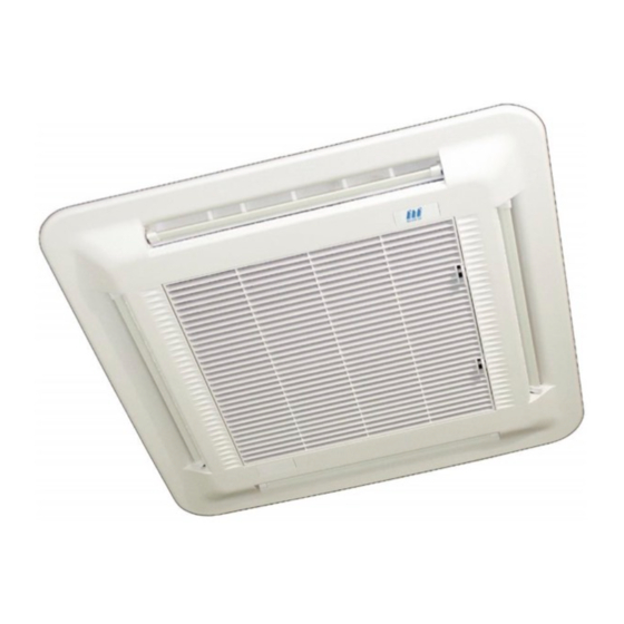
- Page 2 CEILING CASSETTE 875 Split Systems The CC 875 CASSETTE range of split systems consists of the 555 series CC875 cassette indoor units matched with 550 series condensing units, 551 series heat pump outdoor units, 542 series electronic ducted condensing units.
- Page 3 Heronhill - for all your Marstair requirements UNPACKED DIMENSIONS and WEIGHTS CEILING CASSETTE 875 (inc. fascia) Model CC 875 HEIGHT mm WIDTH mm DEPTH mm WEIGHT kg CONDENSING UNITS Model MCU + 60 MCU + 80 MCU + 90 MCU + 100...
- Page 4 Heronhill - for all your Marstair requirements UNIT COMBINATIONS Combinations of indoor unit and (ducted) condensing/heat pump unit can be chosen to give either air conditioning or heat pump systems. Air Conditioning Systems Heat Pump Systems CC 875 MCU +...
- Page 5 Heronhill - for all your Marstair requirements AIR CONDITIONER PERFORMANCE DATA (kW) Note that there are two speed ranges, each giving a low, medium and high speed. Range 2 = for higher duties Range 1 = for lower noise levels...
- Page 6 FRESH AIR SUPPLY (see page 56 for kit details) CC 875 units are fitted with an inlet to allow the installer to provide a fresh air supply The 100mm dia. spigot is available as kit 55200305. The installer must provide ductwork, a screened source of fresh air and an auxiliary fan.
- Page 7 Heronhill - for all your Marstair requirements BRANCH DUCT (see page 57 for kit details) This kit provides an air discharge into an adjacent room The branch duct MUST be taken from the access point on the chassis, (kit details shown on page 57).
- Page 8 Heronhill - for all your Marstair requirements ELECTRICAL DATA ~ R407C a) R407C: CC875 +MCU+ COOLING 1Ph 230V 50Hz 3Ph 400V 50Hz 27°C/19°C, 35°/24°C SYSTEM SYSTEM MAX. FULL LOAD MAX. FULL LOAD INPUT INPUT STARTING AMPS STARTING AMPS CURRENT CURRENT...
- Page 9 Heronhill - for all your Marstair requirements ELECTRICAL DATA ~ R22 d) R22: CC875 + MCU+ COOLING 1Ph 230V 50Hz 3Ph 400V 50Hz 27°C/19°C, 35°/24°C SYSTEM SYSTEM MAX. FULL LOAD MAX. FULL LOAD INPUT INPUT STARTING CURRENT STARTING AMPS CURRENT...
- Page 10 Heronhill - for all your Marstair requirements FUSES / DISJONCTEURS / SICHERUNGEN -HRC Type(EN60269) - MCBs (EN60898) FUSE RATING / TAILLE DES DISJONCTEURS / EMPFOHLENE SICHERUNG (A) 1Ph - 230 V (R407C, R22) CC875 80 (L) (E) 110 (L) (E)
- Page 11 Heronhill - for all your Marstair requirements SOUND POWER and SOUND PRESSURE LEVELS (speed 1 = lowest, 4 = highest: Range 1 = speeds 1,2,3: Range 2 = speeds 2, 3, 4) SOUND POWER LEVELS SOUND PRESSURE LEVELS Frequency Hz...
- Page 12 Heronhill - for all your Marstair requirements UNPACKING / DÉBALLAGE / GERÄT AUSPACKEN Tel: 01823 665660 www.heronhill.co.uk Fax: 01823 665807...
- Page 13 Heronhill - for all your Marstair requirements DIMENSIONS & WEIGHTS / DIMENSIONS ET POIDS / ABMESSUNGEN & GEWICHTE 55500304 ≥ 900 x 900 55200305 55500304 REMOVAL OF CHASSIS / DÉPOSE DU CHASSIS / ABBAU DES GEHAÜSES FOR EASIER ACCESS (SOLID CEILINGS) POUR UN MONTAGE FACILE AU PLAFOND FÜR BESSERE ZUGÄNGLICKEIT (ABGEHÄNGTE DECKEN)
- Page 14 Heronhill - for all your Marstair requirements NOTE: For heating cycle MHPUE - 875, A capillary is fitted to the indoor unit Tel: 01823 665660 www.heronhill.co.uk Fax: 01823 665807...
- Page 15 Heronhill - for all your Marstair requirements CONDENSATE DRAIN PIPING / EVACUATION CONDENSATS / KONDENSWASSERLEITUNG TESTING REINSTALLING THE CHASSIS / REPOSE DU CHÂSSIS / GEHÄUSEEINBAU Tel: 01823 665660 www.heronhill.co.uk Fax: 01823 665807...
- Page 16 Heronhill - for all your Marstair requirements AIR OUTLET BLANKING - KIT 55500316 OBTURATION D’UN CÔTÉ DE SOUFLAGE - KIT 55500316 ABSPERRUNG DES LUFTAUSLASSES - KIT 55500316 55500311 55500312 55500313 55500314 REINSTALLING THE CHASSIS / REPOSE DU CHÂSSIS / GEHÄUSEEINBAU...
- Page 17 Heronhill - for all your Marstair requirements INSTALLATION OF 550 SERIES CONDENSING UNITS AND 551 SERIES HEAT PUMP OUTDOOR UNITS MCU+ = standard condensing unit + FSC + LP MHPUL(E) = electronic heat pump outdoor unit MCUP = German description for MCU+ = standard condensing unit + FSC + LP Units are supplied with loose restrictors which may be required, depending on the indoor unit it is matched with;...
- Page 18 Heronhill - for all your Marstair requirements 542 SERIES DUCTED CONDENSING UNITS These units have electronic fan speed control, start delay timer, HP and LP switches and a contactor fitted as standard; stabilizing brackets are supplied loose . It is generally preferable to fit the following kits (if applicable), prior to mounting the unit:-...
- Page 19 Heronhill - for all your Marstair requirements SUSPENSION MOUNTING The installer must supply 4 x M8 threaded rods with 16 nuts and washers to suit. IMPORTANT: The stabilizing brackets provided MUST be used when suspending a unit. Fit the stabilizing brackets to the top corners of the backpanel and front face using the No. 10 screws provided, (2 per bracket).
- Page 20 Heronhill - for all your Marstair requirements these sizes and lengths is recommended in order to achieve optimum system performance. Smaller sizes may be used, but at the risk of loss of performance. MAXIMUM EQUIVALENT LENGTH EXPANSION FACTORY CHARGE OF SUCTION PIPE (m)
- Page 21 Heronhill - for all your Marstair requirements ELECTRICAL SUPPLY 1. Mains, control and interconnecting cables must be supplied and fitted by the installer. Follow local and national wiring regulations. 2. Cables must be size compatible with the recommended system fuse size.
- Page 22 Electromechanical models In order to automatically switch off the fan in the event of a fire, fit an external switch (240V, 3A, closed to run, volt free contact) between terminal block terminal 2 and the Marstair remote control thermostat terminal 2 ( L).
- Page 23 Heronhill - for all your Marstair requirements Tel: 01823 665660 www.heronhill.co.uk Fax: 01823 665807...
- Page 24 Heronhill - for all your Marstair requirements CC 875 L REMOTE CONTROLLER. CC 875 L indoor units are supplied with a remote controller, wall mounting bracket and two batteries. The controller operates remotely by infrared signals and the bracket may be used to park the controller for convenience.
- Page 25 Heronhill - for all your Marstair requirements EVACUATING & CHARGING / TIRAGE AU VIDE ET CHARGE / EVAKUIEREN &BEFÜLLEN < 1000 microns < 1000 microns (1 Torr) (1 Torr) ☺ ☺ ☺ ☺ >15 mins Yes / Oui / Ja...
- Page 26 Heronhill - for all your Marstair requirements +R407C ? / +R22 ? / +POE ? Add extra refrigerant and polyolester (POE) oil to systems as shown below . Figures assume pipe sizes as shown on page 14. Ajouter du réfrigérant et de l’huile polyolester (POE) selon le tableau ci-dessous. Les tableaux sont basés sur le respect des diamètres de tuyauteries montrés page 14.
- Page 27 Has the effectiveness of condensate removal system been tested and there are no leaks ? Is the air distribution as required? Have you fitted kit 55500316 if 3-way air discharge is required ? Is the IR reciver correctly fitted? CHECK LIST DE L’INSTALLATION DE CC 875 Page Vérifié L’unité est-elle fixée de niveau ? Avez-vous monté...
- Page 28 Heronhill - for all your Marstair requirements CC875 WIRING DIAGRAM BROWN MARRON BRAUN BLACK NOIR SCHWARZ BLUE BLEU BLAU GREEN VERT GRUN GREY GRIS GRAU ORANGE ORANGE ORANGE PINK ROSE ROSA ROUGE TURQUOISE TURQUOISE TUERKIS VIOLET VIOLET VIOLET WHITE BLANC...
- Page 29 Heronhill - for all your Marstair requirements CC875 L WIRING DIAGRAM CC875 E WIRING DIAGRAM Tel: 01823 665660 www.heronhill.co.uk Fax: 01823 665807...
- Page 30 Heronhill - for all your Marstair requirements MCU WIRING DIAGRAMS 1 Phase MCU 60 to 90 3 Phase MCU 60 to 100 3 Phase MCU 130 to 150 Tel: 01823 665660 www.heronhill.co.uk Fax: 01823 665807...
- Page 31 Heronhill - for all your Marstair requirements MCU(+) WIRING DIAGRAMS 1 Phase MCU+ 60 to 90 3 P h a s e M C U + 6 0 t o 1 0 0 3 Phase MCU+ 130 to 150 Tel: 01823 665660 www.heronhill.co.uk...
- Page 32 Heronhill - for all your Marstair requirements MHPUE WIRING DIAGRAMS 1 Phase MHPUE 80 Tel: 01823 665660 www.heronhill.co.uk Fax: 01823 665807...
- Page 33 Heronhill - for all your Marstair requirements 3 Phase MHPUE 80 3 Phase MHPUE 100 to 150 Tel: 01823 665660 www.heronhill.co.uk Fax: 01823 665807...
- Page 34 Heronhill - for all your Marstair requirements MHPUL WIRING DIAGRAMS 1 Phase MHPUL 80 3 Phase MHPUL 30 to 90 Tel: 01823 665660 www.heronhill.co.uk Fax: 01823 665807...
- Page 35 Heronhill - for all your Marstair requirements 3 Phase MHPUL 100 to 150 Tel: 01823 665660 www.heronhill.co.uk Fax: 01823 665807...
- Page 36 Heronhill - for all your Marstair requirements ELECTRONIC DCUE WIRING DIAGRAMS 1 Phase DCUE 60 1 Phase DCUE 80 Tel: 01823 665660 www.heronhill.co.uk Fax: 01823 665807...
- Page 37 Heronhill - for all your Marstair requirements 3 Phase DCUE 60 to 80 Tel: 01823 665660 www.heronhill.co.uk Fax: 01823 665807...
- Page 38 Heronhill - for all your Marstair requirements INTERCONNECTING WIRING / INTERCONNEXIONS / VERBINDUNGSVERDRAHTUNG CC875 Tel: 01823 665660 www.heronhill.co.uk Fax: 01823 665807...
- Page 39 Heronhill - for all your Marstair requirements Tel: 01823 665660 www.heronhill.co.uk Fax: 01823 665807...
- Page 40 Heronhill - for all your Marstair requirements Tel: 01823 665660 www.heronhill.co.uk Fax: 01823 665807...
- Page 41 Heronhill - for all your Marstair requirements CC875 ELECTROMECHANICAL REMOTE CONTROLLER OPERATING INSTRUCTIONS 97200211 (RCC 30 ELECTRONIC) USER MAINTENANCE - FILTER CLEANING Tel: 01823 665660 www.heronhill.co.uk Fax: 01823 665807...
- Page 42 Heronhill - for all your Marstair requirements 'L' INFRARED REMOTE CONTROL • The handset should be pointed towards the unit. • Two seconds after the last button press, the whole displayed programme is automatically transmitted. • The unit responds with 1 beep.
- Page 43 Heronhill - for all your Marstair requirements 7. Setting the ON Time Press the TIMER ON set ‘S’ button and step to the required ON time. Hold the button down for repeated stepping. Press the TIMER ON ‘C’ button to cancel the ON time.
- Page 44 Heronhill - for all your Marstair requirements CC875 E REMOTE CONTROL HANDSET OPERATING INSTRUCTIONS Cool/Heat Modes (2.3): Fan Speeds (2.2): Cooling only Low fan speed Heating only High fan speed Auto cool/heat Boost fan speed Transmit Fan only (2.1) Auto High...
- Page 45 Heronhill - for all your Marstair requirements To change the fan speed: Illuminate the display (blue button). 2 3 4 Press (fan speed) button - the fan symbol will pulse. 2/3/4/23/2 4 Press the + or - (• or – ) button to select the 5 fan speeds (see page 2), whilst pointing the the unit, (unless the handset is wire connected).
- Page 46 Heronhill - for all your Marstair requirements NOTES: If an illogical selection is made (e.g. 'off' time earlier than 'on' time, or 'on' time with no 'off' time, or 'off' time with no 'on' E"" time), the programme will not move on to another day, or transmit, until the error is removed.
- Page 47 Heronhill - for all your Marstair requirements Low battery power warning Low handset battery power is indicated by the battery symbol NOTES: When required, replace the battery with an equivalent alkaline type ensuring that the connector is firmly in position.
- Page 48 Heronhill - for all your Marstair requirements HEATER KITS 1kW 55500311 2kW 55500312 3kW 55500313 4kW 55500314 This kit is for use on CC875 and CWC875 indoor units. (It MUST NOT be fitted to CWCH875, which have an LPHW coil factory fitted).
- Page 49 Heronhill - for all your Marstair requirements FITTING THE HEATER ELEMENTS (Numbers refer to the exploded view) 1. Fit two edge clips centrally on the bottom lugs of the coil support brackets A & C (#1) 2. Manipulate the heater assembly into the unit underneath the top fixing lugs on the coil brackets: angle the element assembly to effect correct positioning (#2).
- Page 50 Heronhill - for all your Marstair requirements WIRING 1kW / 2kW / 3kW KITS 1. Connect the blue wire(s) from the heater element(s) to the in line connectors located on the inside of the coil in- fill plate, opposite the factory fitted blue wire(s).
- Page 51 Heronhill - for all your Marstair requirements 4kW KIT: ‘L’ UNITS: RELAY WIRING 1. Remove the orange wire from the kit relay and discard. 2. Join the piggy-back end of the short orange kit wire to the brown wire (4kW brown + orange) already connected to the pcba relay.
- Page 52 Heronhill - for all your Marstair requirements 5m HIGH CONDENSATE PUMP KIT 55500303 This kit is for use on all versions of CC875 indoor units and is suitable for condensate removal where a lift of up to a maximum 5m is required. The pump will run on demand. The sensor has a high level alarm which will switch off the cooling signal until the condensate has dropped below a preset level.
- Page 53 Heronhill - for all your Marstair requirements FITTING THE 5m HIGH CONDENSATE PUMP TO 875 UNITS 1 E/M models: Remove and discard the red link wire between black plug JP10 and terminal C on the lift pump pcba. Remove the yellow wire from second terminal C on the lift pump pcba.
- Page 54 Heronhill - for all your Marstair requirements 5M CONDENSATE DRAIN TESTING APPLICATION NOTES The pump will work against a 5m head. Flow rate is highest with minimum head. Long lengths of drain pipe should not be exposed to the outdoor ambient, otherwise freezing of condensate may occur during winter operation.
- Page 55 Heronhill - for all your Marstair requirements BMS ALARM INTERFACE KIT 53800423 By fitting a BMS alarm interface kit, a simple common alarm signal is available for volt free input to a BMS network. Power failure, or any other notifiable alarm state, causes the output relay to de-energise.
- Page 56 Heronhill - for all your Marstair requirements FRESH AIR INLET KIT 55200305 This kit is for use on all CC875 indoor units to provide fresh air to the conditioned space. ITEM DESCRIPTION Spigot 100mm diameter Screw No. 10 The maximum fresh air that can be introduced into the unit is 5% of the total air volume.
- Page 57 Heronhill - for all your Marstair requirements BRANCH DUCT SPIGOT 55500304 This kit provides an air discharge into an adjacent room for all CC875 ceiling cassettes. ITEM DESCRIPTION Spigot 150mm diameter Screw No. 10 This kit MUST be fitted prior to installing the unit.
- Page 58 Heronhill - for all your Marstair requirements WALL MOUNTED REMOTE TEMPERATURE SENSING KIT 53800402 This kit is for use with CC875 ‘E’ units where it is desirable to sense room temperature at the wall rather than the unit. NOTE:An EMC Termination Kit (55200301) MUST be used.
- Page 59 Heronhill - for all your Marstair requirements EMC TERMINATION KIT 55200301 This termination gland is required on all CC875 E units wherever low voltage signal cables are used (see table below), to maintain compliance with the EMC Directive. One termination gland can be used for up to 3 cables.
- Page 60 Heronhill - for all your Marstair requirements VANE MOTOR KIT 55500305 This kit is for on all versions of CC 875 indoor cassette units with heating capability. The vane motor automatically deflects the vanes downwards during heating and returns them for horizontal discharge during cooling and dead band.
- Page 61 Heronhill - for all your Marstair requirements 2. On L and E units, unclip the receiver pcba (Fig. 4 #1). 3. Release the internal electrics tray (two screws, Fig. 4 #2); remove the fan cowl (four screws). 4. On L and E units, slide the return air sensor from its tie wraps on the fan guard.
- Page 62 Heronhill - for all your Marstair requirements EXPLODED VIEW OF CC875 with COMPONENT IDENTIFICATION Top panel Capacitor Suspension bracket Fan motor Heat exchanger Coil blanking panel Electric box cover External electrics box Chassis Fresh air cover Coil bracket Heater bracket/clip...
- Page 63 Heronhill - for all your Marstair requirements EXPLODED VIEW OF FASCIA AND VANE ASSEMBLY LED cover Vane motor Fascia Double yoke Grille Spider Filter Actuator arm Badge Vane connector Air deflector vane Vane bearing Vane end cap Vane end cap...
- Page 64 Heronhill - for all your Marstair requirements MCU(+) / MHPUL(E) COMPONENT IDENTIFICATION (DOUBLE FAN UNIT SHOWN) Rear access panel Handle Fuse terminal Bulkhead panel Front access panel Fuse HP switch (manual: Accessory) Fan guard Terminal (screw - screw) Reversing valve (MHPUL(E) only...
- Page 65 Heronhill - for all your Marstair requirements DCUE COMPONENT IDENTIFICATION Float Switches Fan Assembly Expansion Assembly Panel Right Hand Access Service Valve Accumulator Panel Electrics Access Spire Clip Pull Handle Switch LP Auto Service Valve Switch HP Auto Isolator Terminal 4 Way...
- Page 66 Heronhill - for all your Marstair requirements GENERAL FAULT FINDING (ALL SYSTEMS) CONDITION POSSIBLE CAUSE ACTION Check fuse rating and replace if necessary. Check for Indoor fan motor will not run No electric supply at socket or switched fuse box...
- Page 67 Heronhill - for all your Marstair requirements SPECIFIC FAULT DIAGNOSIS FOR CC 875L UNITS CONDITION POSSIBLE CAUSE ACTION Check for alarms LEDs flashing - see table below If NO external connections are made to alarm terminal 5, the presence of an alarm condition can be tested for by checking for mains voltage at terminal 5;...
- Page 68 Heronhill - for all your Marstair requirements SPECIFIC FAULT DIAGNOSIS FOR CC875 ‘E’ UNITS A fully electronic system comprising CC875 ‘E’ with MHPUE or DCUE communicates between the units by digital codes. Signals are transmitted every 10 seconds, therefore a delay of up to 10 seconds could occur before the system responds to a command. Similarly if the communication link is broken, the outdoor unit will shut down within 15 seconds.
Need help?
Do you have a question about the CC 875 and is the answer not in the manual?
Questions and answers