Advertisement
Advertisement
Table of Contents

Related Manuals for Marstair CKC 20 1/50


Summary of Contents for Marstair CKC 20 1/50
- Page 1 TECHNICAL MANUAL CKC CONDENSING UNITS 55008418-01...
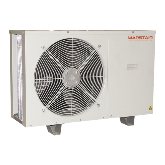
- Page 2 REFRIGERANT COMPONENT IDENTIFICATION CKC GENERAL Marstair Ltd recommend that personnel working on this equipment be skilled and fully conversant with the appropriate Air Conditioning, Refrigeration and Electrical practices and have sound knowledge of current Industrial Safe Working practices. These units are supplied pre-charged with R407C refrigerant and polyolester oil.
-
Page 3: Part Numbers
PART NUMBERS SINGLE (1ph) THREE PHASE (3ph) MODEL PHASE PART NUMBER (1ph) PART CKC 15 1/50 55020769 55020774 CKC 20 1/50 NUMBER 55020720 55020775 CKC 30 1/50 55020730 55020776 CKC 40 1/50 55020741 55020777 CKC 50 1/50 55020722 55020724 CKC 60 1/50... - Page 4 KITS DESCRIPTION MODEL PART NUMBER Pressure switch (HP manual) 55000398 Volt free relay 55000395 15-80 55021100 Wall mount brackets 90-200 55021101 55000409 20-30 55000410 Overload (standard on 3ph) 40-60 55000446 80-90 55000449 PTC (hard start 1ph) 15-40 55000412 15,20,40 55000414 CSR (hard start 1ph) 55000415 1ph 15-60...
- Page 5 SPECIFICATION DETAILS PERFORMANCE DATA Nominal cooling capacity 10.9 12.4 13.9 14.7 17.1 19.9 R407C charge supplied 1030 1000 1240 1690 2000 1880 2060 2520 4170 4170 4540 4640 5480 Operating weight kg 1 Ph (230V 50Hz) Power (nominal) Starting current LRA Nominal current FLA 10.2 11.5...
- Page 6 CKC 15 – 200 CAPACITIES SATURATED SUCTION TEMPERATURE °C AIR ON TO MODEL -2.5 CONDENSER COOLING CAPACITY AND POWER INPUT kW °C CAP. POWER CAP. POWER CAP. POWER CAP. POWER CAP. POWER CAP. POWER 1.93 0.69 2.14 0.70 2.35 0.70 2.55 0.71 2.76...
- Page 7 MOUNTING CKC These units are designed to stand on a flat surface. If the unit is to be wall mounted the following kits are available. CKC 15-80 CKC 90-200 Mounting Bracket 55021100 55021101 Whether floor or wall mounted, it is essential that the mounting surface is capable of supporting the unit weight.
- Page 8 CKC 130 – 200 ( Dimensions in mm.) MOUNTING MOUNTING HOLES HOLES NEW STYLE FEET OLD STYLE FEET MODEL Weight (kg) CKC 130 1000 1020 CKC 150 1000 1020 CKC 165 1000 1020 CKC 180 1100 1215 CKC 200 1100 1215 55008418-01...
- Page 9 SUSPENSION MOUNTED The installer must supply 4 x M8 threaded rods with 16 nuts and washers to suit. IMPORTANT • The stabilizing brackets provided must be used when suspending a unit. • Fit the stabilizing brackets to the top corners of the backpanel and front face using the No 10 screws provided, (2 per bracket) •...
-
Page 10: Pipework
PIPEWORK Supplied male flare connections (sizes in inches) Model Size 15 20 30 40 50 60 80 90 100 130 150 165 180 200 Expansion 3/8 3/8 3/8 3/8 3/8 3/8 1/2 1/2 1/2 1/2 1/2 1/2 1/2 1/2 3/8 3/8 1/2 1/2 1/2 5/8 5/8 5/8 3/4 3/4 3/4 3/4 7/8* 7/8* Suction * Brazed connections MAXIMUM PIPE RUNS... -
Page 11: Pipe Sizes
PIPE SIZES MAXIMUM LENGTH OF EQUIVALENT EXPANSION LINES UNIT SUCTION LINE PIPE SIZES (m) SIZE ⅜ ⅝ ⅞ 1⅛ 1⅜ ⅜ ⅝ ½ ¾ ½ ¾ RESTRICTORS Outdoor units (cool only) have optional kit expansion assemblies with cooling restrictors fitted. Restrictor 0.033 0.033... -
Page 12: Electrical
ELECTRICAL The installer supplies mains, control and interconnecting cables: equipment must be earthed. Wiring must be carried out in accordance with local and national codes. Interconnecting wiring diagrams are in the indoor unit installation instructions. Mains supply cables must be size compatible with the recommended fuse (see indoor unit instructions). An all pole isolator switch should be positioned within easy reach of the indoor unit. -
Page 13: If Additional Refrigerant Is Required
REFRIGERANT FACTORY CHARGE FOR 7.5M RUNS AT UK CONDITIONS 1030 1000 1240 1690 2000 1880 2060 2520 4170 4170 4540 4640 5480 IF NO ADDITIONAL REFRIGERANT CHARGE IS REQUIRED: Open the valves very slowly using a 5 or 8mm Allen key. Replace the caps on the service ports, (torque to 25NM). - Page 14 HEAD PRESSURE CONTROL SAGINOMIYA (RGE – ZIN4 – SH) The head pressure controller is factory set to suit the refrigerant. It may be necessary to adjust this to suit site conditions, to raise or lower the nominal head pressure. a. With the system switched off, connect a high pressure gauge to the liquid line service valve. b.
- Page 15 10. HEAD PRESSURE CONTROL ALCO (FSY-42S) & SAGINOMIYA (XGE-4C) The head pressure controller is factory set to suit the refrigerant. It may be necessary to adjust this to suit site conditions, to raise or lower the nominal head pressure. ALCO (FSY-42S) a.
-
Page 16: Component Identification
COMPONENT IDENTIFICATION CKC 15 - 100 HANDLE CONTACTOR FRONT ACCESS OVERLOAD FAN GUARD HEAT EXCHANGER COIL FASCIA PANEL REAR ACCESS PANEL CORNER PANEL MAINS TERMINAL COVER SUPPORT BRACKET FAN CAPACITOR FAN / MOTOR ASSEMBLY BULKHEAD PANEL END CLAMP HP SWITCH (MANUAL, OPTION) TERMINAL EXPANSION ASSEMBLY FUSE... - Page 17 CKC 130 – 200 VALVE PANEL FUSE TERMINAL BASE FUSE MOUNTING FOOT TERMINAL LP SWITCH TERMINAL (4 WAY) COMPRESSOR CONTACTOR HANDLE EARTH TERMINAL FRONT ACCESS PANEL END CLAMP FAN GUARD OVERLOAD FASCIA PANEL HEAT EXCHANGER COIL CORNER PANEL FAN CAPACITOR SUPPORT BRACKET MAINS TERMINAL COVER FAN / MOTOR ASSEMBLY...
Need help?
Do you have a question about the CKC 20 1/50 and is the answer not in the manual?
Questions and answers