Advertisement
Quick Links
Advertisement

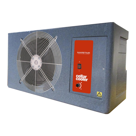
Summary of Contents for Marstair CX Series
- Page 1 TECHNICAL MANUAL CX(E) SPLIT SYSTEMS CX(E) LOW TEPERATURE SPLIT SYSTEMS 55908014-23...
- Page 2 INDEX CONTENTS PAGE PART NUMBERS, UNIT COMBINATIONS, OPTIONS DIMENSIONS & WEIGHTS, PERFORMANCE DATA AIR FLOW, SOUND POWER AND SOUND PRESSURE LEVELS ELECTRICAL DATA CX(E) DIMENSIONS INSTALLATION CKC PIPEWORK CKC REFRIGERANT ELECTRICAL: CONNECTIONS & FUSES CX MATCHES WIRING DIAGRAMS CX(E) CONTROLS CKC INSTALLATION: DIMENSIONS COMPONENT IDENTIFICATION CX(E) UNITS...
- Page 3 PART NUMBERS MODEL CX 30 CX 40 CX 50 CX 70 CX 90 PART NUMBER 55917001 55917002 55917003 55917004 55917005 MODEL CXE 30 CXE 40 CXE 50 CXE 70 CXE 90 PART NUMBER 55917017 55917016 55917015 55917014 55917019 CKC 20 CKC 30 CKC 50 CKC 80...
- Page 4 DIMENSIONS & WEIGHTS MODEL UNPACKED PACKED CX(E) HEIGHT WIDTH DEPTH WEIGHT HEIGHT WIDTH DEPTH WEIGHT MODEL UNPACKED PACKED WEIGHT WEIGHT HEIGHT WIDTH DEPTH HEIGHT WIDTH DEPTH 1000 1090 1000 1090 1000 1090 1000 1090 PERFORMANCE DATA (kW) Above 8°C System Matches 12.7/10 &...
- Page 5 AIR FLOWS SOUND POWER AND SOUND PRESSURE LEVELS INDOOR UNIT SOUND POWER LEVELS MAXIMUM SOUND PRESSURE SPEED LEVELS Frequency Hz dB(A) CX(E) 30 69.1 67.7 67.6 65.6 62.2 CX(E) 40 69.1 67.7 67.6 65.6 62.2 CX(E) 50 71.7 69.2 69.1 67.1 63.2 58.5...
- Page 6 ELECTRICAL DATA Above 8°C System Matches 1 PH 230V 50Hz INPUT POWER FULL LOADS AMPS SYSTEM MAX. COOLING HEATING COOLING HEATING STARTING CURRENT MODEL AMPS AMPS AMPS INDOOR/OUTDOOR CX(E) 30 + CKC 20 13.8 13.8 CX(E) 40 + CKC 30 13.8 CX(E) 50 + CKC 50 12.3...
- Page 7 CX(E) DIMENSIONS 888 (Fixing centres) 17.5 TOP VIEW (Ceiling Mounted) 17.5 MIN. MIN. SIDE VIEW FRONT VIEW SIDE VIEW (Wall mounted) (Wall mounted) (Ceiling mounted) X = Interconnecting Wiring = Suction MIN. 500 = Liquid / Expansion FOR SIDE ACCESS 65 TYP.
- Page 8 INSTALLATION CONTENTS PARTS DESCRIPTION ACTION Envelope containing operating instructions and Pass to the end user. Declaration of Conformity Mounting brackets Use to hang unit. Drain Stub/Nut/Gasket Fitted by installer. Drain stub adaptor Convert to ¾" drain if required. Screw M5 To fix brackets to unit.
- Page 9 MAXIMUM EQUIVALENT LENGTH OF SUCTION LINE PIPE SIZES (m) LIQUID LINE SYSTEM 3/8" 1/2" 5/8" 3/4" 1/4" 3/8" 1/2" CX(E)40 + CKC20 CX(E)50 + CKC40 CX(E)70 + CKC60 CX(E)90 + CKC80 B. USING SUCTION AND EXPANSION LINES The expansion assembly must be removed from the indoor unit and connected to the outdoor unit allowing a pipe run of up to 80m, including a maximum lift of 20m (CKC20 maximum 50m with 7.5m lift).
- Page 10 RESTRICTORS Indoor units are supplied with restrictors fitted. NOTE When the CXE 40 is matched with a CKC 20. The restrictor in the indoor unit must be changed to 0.033" When the CXE 50 is matched with a CKC 40. The restrictor in the indoor unit remains as a 0.050"...
- Page 11 Liquid line Expansion line Charge 1/4" 3/8" 3/8" 1/2" 5/8" based on:- 25 g/m 60 g/m 16 g/m 30 g/m 48 g/m Additional POE oil 25g per 350g of additional refrigerant to a maximum of 300g NOTE: The new 50 Series CKC are supplied with a Nitrogen holding charge. See pages 12 & 13 for refrigerant charge information.
- Page 12 CX 17 SERIES MATCHED WITH CKC 20 SERIES UNITS WITH 5MM FINNED TUBE COIL Part Number Liquid Line System CX(E)30 + CKC20 55917001 55917017 55020720 1054 CX(E)40 + CKC30 55917002 55917016 55020730 1184 1484 1784 R407C CX(E)50 + CKC50 55917003 55917015 55020722 1286 1586 1886...
- Page 13 LOW TEMPERATURE CXE 17 SERIES MATCHED WITH CKC 50 SERIES UNITS WITH MICROCHANNEL COIL Liquid Line System CXE 40 + CKC 20 55917016 55020720 CXE 50 + CKC 40 55917015 55020741 1276 1576 R407C CXE 70 + CKC 60 55917014 55020740 1070 1370 1670 1970...
- Page 14 WIRING DIAGRAM 14/20 55908014-23...
- Page 15 15/20 55908014-23...
- Page 16 CXE ELECTRONIC COOLING SYSTEM CONTROLS CAREL IR33 Controller ON/OFF SWITCH The switch operates the fan motor and is illuminated when power is supplied to the indoor unit. When switched OFF, the fan stops, the switch remains illuminated and the crankcase heater in the outdoor unit (if fitted) remains live. Minimum Set Temperature 8°C Minimum Set Temperature 4°C INDOOR UNIT OUTDOOR UNIT...
- Page 17 CKC INSTALLATION MOUNTING Whether floor or wall mounted, it is essential that the mounting surface is capable of supporting the unit weight. Leave space around the unit for air circulation and access for installation and maintenance. Dimensions in mm. MODEL CKC 20 CKC 30 CKC 40...
- Page 18 CX INDOOR UNIT COMPONENT IDENTIFICATION Grille De-ice stat (option) Fan / motor Heater assembly (option) Case Drain stub adaptor Wall / ceiling mounting brackets Drain tray Heater bracket Side access panel Coil assembly Electrics box door Thermostat bulb & bracket Digital display (option) Restrictor assembly / extended pipe (option) INSIDE VIEW OF ELECTRICS BOX...
- Page 19 CKC OUTDOOR UNIT COMPONENT IDENTIFICATION 19/20 55908014-23...
- Page 20 Additional POE oil added Pipe run length (ʺ) Suction pipe size (ʺ) Liquid / Expansion pipe size TEV LTD, ARMYTAGE ROAD, BRIGHOUSE, WEST YORKSHIRE, HD6 1QF. TEL: + 44 (0) 1484 405600 FAX: +44 (0) 1484 405620 EMAIL: sales@marstair.com WEB: www.marstair.com 20/20 55908014-23...


Need help?
Do you have a question about the CX Series and is the answer not in the manual?
Questions and answers