Table of Contents
Advertisement
Quick Links
Advertisement
Table of Contents

Related Manuals for ITC TH-0500M


Summary of Contents for ITC TH-0500M
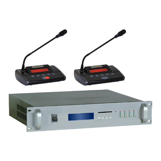
- Page 1 OWNER'S MANUAL INFRARED WIRELESS CONFERENCE SYSTEM TH-0500M...
-
Page 2: Table Of Contents
[Table of Contents] Overview System Configuration and description-----------------------------------------------3 System features-----------------------------------------------------------------------3 Infrared conference system main unit ----------------------------------------------3 1.2.1 Picture of the actual object -----------------------------------------------------------3 1.2.2 Features of infrared conference system main unit -----------------------------------3 1.2.3 Schematic diagram of infrared conference system main unit -----------------------4 1.2.4 Parameter of infrared conference system main unit----------------------------------5 Infrared conference system microphone unit ---------------------------------------5 1.3.1 Picture of the actual object -----------------------------------------------------------5... - Page 3 2.2.1 CAUTION on handling of the microphone unit---------------------------------------15 2.2.2 CAUTION on installation-------------------------------------------------------------16 2.2.3 CAUTION on battery charger handling----------------------------------------------16 2.2.4 CAUTION on battery handing--------------------------------------------------------16 2.2.5 CAUTION on handling the AC adapter-----------------------------------------------16 Identify room layout-----------------------------------------------------------------17 2.3.1 Check coverage area-----------------------------------------------------------------17 2.3.2 The relationship between ceiling height and infrared emitting and receiving coverage area------------------------------------------------------------------------17 2.3.3 Check quantity of receiver unit------------------------------------------------------17 2.3.4 System configuration----------------------------------------------------------------18...
-
Page 4: System Configuration And Description
Overview The infrared conference system has all the advantages of infrared communication complete with wireless receiver microphone units. Wireless infrared technology provides the user with greater flexible whilst configuring the system and freedom of choice when placing microphones, it guarantees conference privacy and protects the system from wiretapping and radio interference. -
Page 5: Schematic Diagram Of Infrared Conference System Main Unit
1.2.3 Schematic diagram of Infrared conference system main unit 1) Power switch (Press I to turn on the power, power indicator is lighting, press O to turn off the power) 2) LCD (Display current mode, online microphone number, activity microphone number and ID) 3) Admin card interface 4) Menu: system volume/LCD contrast/project setting... -
Page 6: Parameter Of Infrared Conference System Main Unit
1.2.4 Parameter of infrared conference system main unit Items Parameter Transmission method Wireless infrared Audio channel Carrier frequency band 6MHz-8MHz Modulation method Receiving sensitivity -85dBM Audio channel Output level -10dB Infrared operating distance >10M Frequency response 100Hz-10KHz S/N Ratio >70dB T.H.D. -
Page 7: Features Of Infrared Delegate Microphone
1.3.2 Features of infrared delegate microphone a. Newly digital design b. Portable table moving and microphone pipe can be pull out. Extended pipe optional. c. Electric capacity type microphone, equipped with windshield cover d. LCD color red/blue (option) e. LCD display microphone ID, signal level, battery level, microphone state, control channel, etc. -
Page 8: Parameter Of Infrared Microphone Unit
1) Annular red indicator lamp to show the microphone state. 2) Unidirectional electret MIC 3) LCD 4) IR sensor 5) Menu/Back key: Press this key to enter menu setting or back after setting 6) Left key 7) Right key 8) MIC ON/OFF key 9) Chairman Priority 10) Up key 11) Down key... -
Page 9: Distributor
1.4 Distributor 1.4.1 Picture of the actual object 1.4.2 Features of distributor a. Adopt impedance balancing branch connector (2 input, 1output) b. Low insertion loss computation c. Perfect plating surface treatment with excellent shielded function 1.4.3 Schematic diagram of distributor 1) BNC terminal: Connector for the BNC coaxial cable connection 2) Mounting and fixing holes: Holes for mounting distributor body 1.4.4 Parameter of distributor... -
Page 10: Infrared Receiver Unit
1.5 Infrared receiver unit 1.5.1 Picture of the actual object 1.5.2 Features of receiver unit a. Adopt mounting hook installation, easy to install. b. Wide-angle, receiving range is approximately 150 degrees. c. Signal gain more than 35dBM d. Adopt low consumption electro circuit e. -
Page 11: Battery Charger
1.6 Battery charger 1.6.1 Picture of the actual object 1.6.2 Features of battery charger a. Input Voltage: AC 230V b. Charges 16 PCS of LIP battery per charging c. Intelligent charging management electro circuit to protect the LIP battery d. Equipped with extendible handle and pulley, easy for moving. 1.6.3 Schematic diagram of battery charger 1) Pulley 2) Extendible handle... -
Page 12: Parameter Of Battery Charger
10.3. Parameter of battery charger Items Parameter Power supply 110V-240V/50Hz~60Hz Consumption Rating 200W Charge quantity MAX charging current of each 700mA Charging time About 8~10 hours unit Charging status Red LED flashing –Charging, Green LED –Full Operating temperature range 0-40 degree Charged Dimensions 620×370×260mm... -
Page 13: Parameter Of External Antenna
1.7.3 Parameter of external antenna Items Parameter Carrier frequency band 915MHz-925MHz Impedance 50Ω MAX cable length Terminal type Dimensions 345×80mm(with bracket) 100g (with bracket) 1.8 Infrared conference system LIP battery 1.8.1 Picture of the actual object 1.8.2 Features of LIP battery a. -
Page 14: Ac Power Adapter
1.9 AC power adapter 1.9.1 Picture of the actual object 1.9.2 Schematic diagram of AC power adapter 1) AC Power plug 2) Transformer 3) DC plug 1.9.3 Parameter of AC power adapter Items Parameter Input voltage AC220V 50Hz~60Hz Output voltage DC 18V 600mA Dimensions 98×70×55mm ( only transformer) -
Page 15: System Installation
2. System installation 2.1 System connection diagram... -
Page 16: Warning
2.2 Warning If the units demonstrate any problems, such as abnormal sound, smoke, heat from or damage to power cables, disconnect the power plug from the outlet and contact your sales representative. If the power plug blades are distorted or discolored, do not use the unit (Main unit, Battery charger) Uncoil the power cables before use, Do not bundle the cables during use, or fie with ... -
Page 17: Caution On Installation
turn down the volume After the battery has been removed and replaced, confirm that the power LED turns 2.2.2. CAUTION on installation After mounting the IR receiver units, be certain that they are securely fastened Do not install the IR receiver units or the microphone units near infrared-emitting ... -
Page 18: Identify Room Layout
2.3 Identify room layout 2.3.1 Check coverage area Real coverage area of conference room (usually coverage area of conference room is smaller than the conference room area) 2.3.2 The relationship between ceiling height and infrared emitting and receiving coverage area. Ceiling Coverage height... -
Page 19: System Configuration
Note: IR receiver unit quantity may increase according to the actual installation place 2.3.4 System configuration. Description Model No. Max Qty Marks IR Main Unit Chairman Microphone Delegate Microphone ≤127 IR Receiver ≤24 Distributor External Antenna Battery Charger LIP Battery AC adaptor Admin Card 2.4 Installation and connection of IR main unit... -
Page 20: Ir Main Unit To Sound System
Please read 2.5 to get detailed information of IR receiver unit installation method. 2.4.3 IR main unit to sound system a. Mono output: Please connect AF OUT interface of IR main unit to input interface of sound equipment by Φ6.3 audio cable b. -
Page 21: Ir Main Unit To External Antenna
Please connect DATA (A-G-B) interface of IR main unit to DATA interface of video processor by RJ45 network cable. Please read the user manual of video processor. 2.4.5 IR main unit to external antenna If the distance between IR main unit and microphone is not far, and there does not have any obstruct, antenna can be connect to the “ANT”... - Page 22 c. When install IR receiver units on ceiling H= the height of the ceiling (M) D= the distance between IR receiver units (M) Be sure to overlap the infrared operating areas by approximately 2M. d. When install IR receiver units on walls H=the height of the IR receiver unit from the floor (M) D= the distance between IR receiver unit (M) Infrared operating distance is approximately 10 m and the receiving range is...
-
Page 23: Installation Diagram Of Ir Receiver Unit
2.5.2 Installation diagram of IR receiver unit a. Install IR receiver units on ceiling b. Install IR receiver units on walls Checking the mounting hook position, mount the IR receiver unit on the mounting bracket. (ii) Then, rotate the IR receiver unit clockwise to fasten it securely. * Be sure that the IR receiver unit is securely fastened. -
Page 24: Wiring Between Ir Receiver Unit And Main Unit When Using Distributors
2.5.3 Wiring between IR receiver unit and main unit when using distributors If the input signals of each IR receiver unit are not in the same phase, the receiving level may decrease. To match the signal phase, the length of the corresponding cables and should be the same;... -
Page 25: Installation Of Ir Microphone Unit
Digital equipment like the digital power amplifier and cable wiring to this.(such as speaker output wiring of the digital power amplifier) Up to 12 IR receiver units can be installed of each channel (total 2 channels) Because the interconnection coaxial cable (50Ω) of IR receiver unit is used for ... -
Page 26: Microphone Operating Range And Distance
2.6.3 Microphone operating range and distance 2.6.4 Examples of square arrangements Example: Conference room area: 286 m Real coverage area: 18×10=180 m Height of the ceiling: 3 m * Please contact us if you need more detailed information during your installation. -
Page 27: System Setting
2.7 System setting 2.7.1 Main unit setting Please insert Admin card to the main unit before setting, or user can not change the setting of main unit. There are four function keys on main unit: MENU, (LEFT), (LEFT), ENTER a. System mode setting: System support six modes setting by main unit (FIFO 1, FIFO 2, FIFO 3, LIMIT 1, LIMIT 2, LIMIT 3), user can set these mode by LEFT &... -
Page 28: Microphone Setting
the setting. 2.7.2. Microphone setting There are five function keys on microphone unit: MENU/BACK, (LEFT), (RIGHT), (UP), (DOWN). Press MENU/BACK to enter setting, and then select the setting items by LEFT & RIGHT a. LCD CONTRAST: 43-63 Levels, default setting is 55. b. -
Page 29: System Lcd
2) DTX should be same as main unit DTX. 3) Microphone default setting is MAX 4) Setting method: Press RIGHT, and turn on the microphone with POWER key at the same time, microphone LCD will display DTX POWER setting interface. User can set the microphone DTX by UP &... -
Page 30: Troubleshooting
= Battery full, microphone was powered by external DC power. 2) Signal level. = Signal disconnect = Signal very weak = Signal weak = Signal good = Signal strong 3) Microphone ON/OFF state 4) Current microphone ID number 5) Current microphone data channel (data channel must same as main unit channel) 6) Microphone will auto-close in 99 seconds if there is no pick-up sound after turn on. - Page 31 *1. The battery life is usually approximately 300 charge cycles.
Need help?
Do you have a question about the TH-0500M and is the answer not in the manual?
Questions and answers