Table of Contents
Advertisement
Quick Links
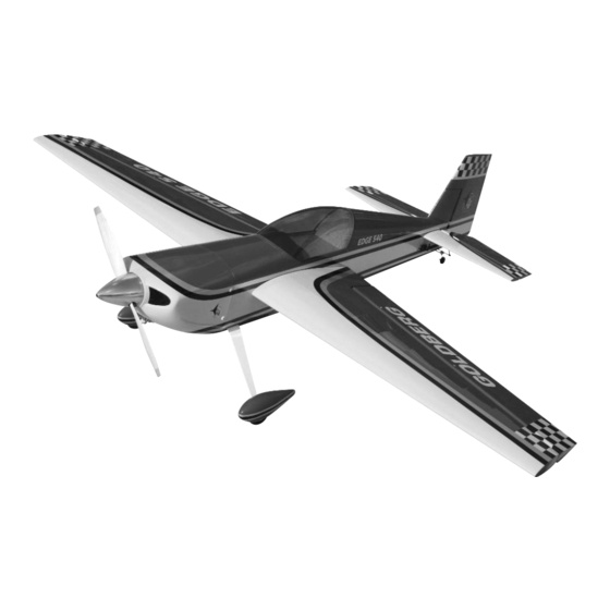
77" Edge 540 ARF
INSTRUCTIONS
A radio-controlled model is not a toy and is not intended for persons under 16 years old. Keep
this kit out of the reach of younger children, as it contains parts that could be dangerous. A radio-
controlled model is capable of causing serious bodily injury and property damage. It is the buyer's
responsibility to assemble this aircraft correctly and to properly install the motor, radio, and all other
equipment. Test and fly the finished model only in the presence and with the assistance of another
experienced R/C flyer. The model must always be operated and flown using great care and common
sense, as well as in accordance with the Safety Code of the Academy of Model Aeronautics
(www.modelaircraft.org). We suggest you join the AMA and become properly insured prior to flying
this model. Also, consult with the AMA or your local hobby dealer to find an experienced instructor in
your area. Per the Federal Communications Commission, you are required to use only those radio fre-
quencies specified "for Model Aircraft."
Carl Goldberg Products has inspected and certified the components of this aircraft. The company urges the buyer to perform his
own inspection, prior to assembly, and to immediately request a replacement of any parts he believes to be defective for their
intended use. The company warrants replacement of any such components, provided the buyer requests such replacement with-
in a period of 90 days from the date of purchase and provided the defective part is returned, if so requested by the company.
No other warranty, expressed or implied, is made by the company with respect to this kit. The buyer acknowledges and under-
stands that it is his responsibility to carefully assemble the finished flying model airplane and to fly it safely. The buyer hereby
assumes full responsibility for the risk and all liability for personal or property damage or injury arising out of the buyer's use of the
components of this kit.
CARL GOLDBERG PRODUCTS, LTD.
P.O. Box 818 Oakwood GA 30566 Phone #678-450-0085 Fax # 770-532-2163 www.carlgoldbergproducts.com
WARNING
LIMITED WARRANTY
© Copyright 2005 Carl Goldberg Products LTD
1
TM
Advertisement
Table of Contents

Related Manuals for Carl Goldberg Products Edge 540 ARF


Summary of Contents for Carl Goldberg Products Edge 540 ARF
- Page 1 LIMITED WARRANTY Carl Goldberg Products has inspected and certified the components of this aircraft. The company urges the buyer to perform his own inspection, prior to assembly, and to immediately request a replacement of any parts he believes to be defective for their intended use.
- Page 2 Building supplies needed the 77” Edge 540 ARF to be one of the most responsive, in-the-grove aircraft on the market. Hobby knife w/#11 blades...
- Page 3 Black #874 COVERING The 77” Edge 540 ARF is covered in a premium polyester film chosen by many of the world's top flyers for its beau- ty, toughness, and ease of application and repair. It is not uncommon for ARF's to develop a few wrinkles in transit.
-
Page 4: Wing Assembly
WING ASSEMBLY CONTROL HORN PART NAMES adjustable control washer horn 6-32 x 3” bolt Transfer the mark from the bottom of the aileron to the top side. AILERON CONTROL HORN INSTALLATION Collect the following items Using a 1/8” drill, drill half way through the aileron hole from both top and bottom till the (4) 4-40 x 3”... -
Page 5: Aileron Servo Installation
Place 1 drop of oil on each of the hinge joints at the center. This is to keep the hinges loose and prevent epoxy from sticking at the joint. Caution: Do not get any oil on the length of the hinge or it will not glue into the surface. - Page 6 Aileron Servos Pushrods COLLECT THE FOLLOWING ITEMS: (4) 4-40 X 3-1/8” PUSHRODS THREADED BOTH ENDS (4) 4-40 CLEVIS (4) SILICONE CLEVIS RETAINERS (4) 4-40 nuts Attach the outboard servo to one side of the Y-connector. Insert the Y-connector into the outboard hole and guide down the wing to the inboard servo hole.
- Page 7 FUSELAGE HATCH The top front half of the fuselage is a hatch. Remove the 4-40 socket head bolts on the side of the fuse- lage to disengage the hatch. WHEEL AND WHEEL PANTS I nsert the gear legs through the slots in the fuselage side.
- Page 8 Install the blind nut in the wheel pant using the HINGING RUDDER 4-40 bolt to pull it into the hole. Landing Gear Wheel Pant Wheel Collars Locate the rudder and four hinges Trial fit the hinges to make sure they all go up to the hinge pin in rudder and fin.
- Page 9 One of the bracket collars has two holes threaded into it, one on each side. This one is the top one. Put the bottom bracket collar on the axle and Install the 6-32 x 3-1/2” threaded rod in the insert it through the spring bracket. hole with a nylon washer and nylon nut on each Put the top collar bracket on top and tightened side...
-
Page 10: Stabilizer And Elevator Installation
Stabilizer and Elevator Installation Make a mark 1/4” inboard from the center of the stab and 1/8” back from the top of the bevel. Transfer this mark to the other side of the stab. Using a 1/8” drill, drill the hole for the control horn. -
Page 11: Elevator Pushrods
Insert the aluminum tubes in the fuselage. The long one goes in the rear. To get the proper throw you will need a 1-1/4” servo arm. The adjustable horn should be screwed 1” up the screw on the horn. Screw the control rod into the nylon horn and screw the 4-40 nut then the clevis on the other end. -
Page 12: Rudder Servo Installation
Take the end of the braided cable and thread Rudder Servo Installation through one of the brass cable swages, then through one of the rigging couplers. Loop the cable back through the cable swage. Take the end and loop it back around the cable swage and go through the swage again. - Page 13 Tape the rudder in the neutral position. Make sure the rudder servo is centered. Thread each cable through one of the swages, through the rigging coupler and back through the swage. Pull both cables tight, loop through the swage Slide the silicone keeper on the clevis and again, and crimp.
-
Page 14: Engine Installation
ENGINE INSTALLATION The Motor you choose may have a different type installation as show. We show an O.S. 1.6 motor, this motor has more than enough power to make this plane perform to its limits. If you choose this powerful motor then you must make sure that you go over all high stress joints with white glue or a epoxy. -
Page 15: Cowl Mounting
Mark the location of the mounting holes on the Mount the engine using the four 3mm x 25mm mounts. screws and flat washers. Remove the engine and drill a 1/8” hole at Be sure and use thread lock on the bolts. each location. - Page 16 To locate the needle valve outlet hole, tape a piece of paper to the side of the fuselage with the needle valve extension through the paper. Mount the cowl in position and hold in place using masking tape. Note: You will have to make a cut out for the engine head on the bottom of the cowl.
-
Page 17: Throttle Servo Installation
Reinstall the cowl and transfer the hole loca- tion to the cowl. The pipes can be cut just below the cowl and Mount the servo in the tray using the hard- the cowl will go on and off without removing ware supplied with the radio. -
Page 18: Fuel Tank Installation
Fuel Tank Installation Collect the following items: (1) fuel tank (1) cap assembly (1) clunk (1) pick up tube (3) aluminum tubes Drill a 5/32” hole in line with your throttle arm. It may be necessary to make an offset bend in the throttle rod to make it align with the arm. - Page 19 Measure down from the line and allow for the thickness of the tank floor and glue the 3/8” square balsa to each side of the fuselage. Attach the fuel pickup line to one of the straight tubes. Attach the clunk to the other end. Glue the tank support floor in place on top of Fit assembly into the tank and adjust the the 3/8”...
- Page 20 Receiver and Switch Installation Switch mount positions are provided on both sides of the fuselage, either can be used. A mount for the receiver is provided just behind the servo tray and under the rudder cables.
-
Page 21: Canopy Mounting
wing bolt Canopy Mounting. wax paper Trial fit the wing tube into each wing panel.If Caution: Do not glue the canopy to the hatch very tight try a little wax on the wing tube work without the hatch mounted to the fuselage. it in and out till it frees up.
Need help?
Do you have a question about the Edge 540 ARF and is the answer not in the manual?
Questions and answers