Table of Contents
Advertisement
Quick Links
Instructions
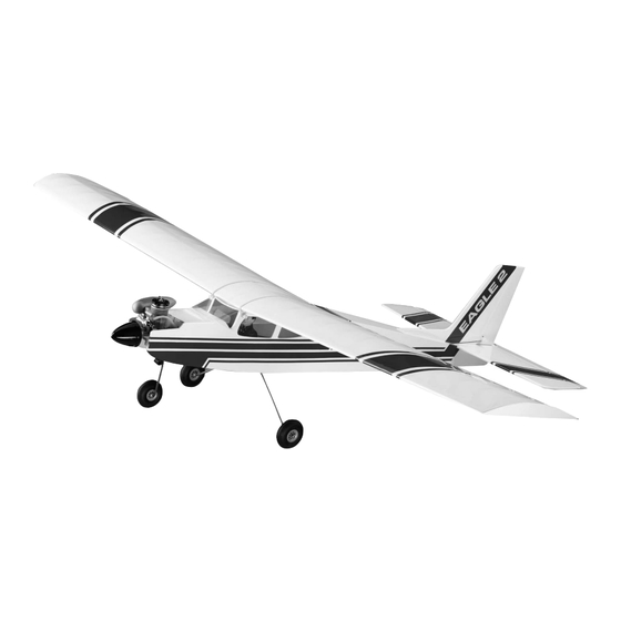
Congratulations on choosing the Eagle 2 ARF! This aircraft has been carefully engineered to pro-
vide you with all the terrific flight characteristics of the Goldberg Eagle 2 kit, a plane that has helped
thousands of R/C pilots earn their wings. Your Eagle 2 ARF's sure-footed ground handling, superb
stability, and super-slow landings will help make your early attempts at R/C flying successful. But
first, take the time to read carefully through this booklet. It will speed the assembly process, help
ensure that the plane you take to the field performs properly, and will increase your understanding of
the challenging and fun sport of R/C flying.
A radio-controlled model is not a toy and is not intended for persons under 16 years old. Keep
this kit out of the reach of younger children, as it contains parts that could be dangerous. A radio-
controlled model is capable of causing serious bodily injury and property damage. It is the buyer's
responsibility to assemble this aircraft correctly and to properly install the motor, radio, and all other
equipment. Test and fly the finished model only in the presence and with the assistance of another
experienced R/C flyer. The model must always be operated and flown using great care and common
sense, as well as in accordance with the Safety Code of the Academy of Model Aeronautics (5151
Memorial Drive, Muncie, IN 47302, 1-800-435-9262). We suggest you join the AMA and become prop-
erly insured prior to flying this model. Also, consult with the AMA or your local hobby dealer to find an
experienced instructor in your area. Per the Federal Communications Commission, you are required
to use only those radio frequencies specified "for Model Aircraft."
Carl Goldberg Products has inspected and certified the components of this aircraft. The company urges the buyer to perform his
own inspection, prior to assembly, and to immediately request a replacement of any parts he believes to be defective for their
intended use. The company warrants replacement of any such components, provided the buyer requests such replacement with-
in a period of one year from the date of purchase and provided the defective part is returned, if so requested by the company.
No other warranty, expressed or implied, is made by the company with respect to this kit. The buyer acknowledges and under-
stands that it is his responsibility to carefully assemble the finished flying model airplane and to fly it safely. The buyer hereby
assumes full responsibility for the risk and all liability for personal or property damage or injury arising out of the buyer's use of the
components of this kit.
CARL GOLDBERG PRODUCTS, LTD.
P.O. Box 88 Oakwood GA 30566 Phone #678-450-0085 Fax # 770-53-63 www.carlgoldbergproducts.com
© Copyright 1999 Carl Goldberg Products LT.
EAGLE 2
WARNING
LIMITED WARRANTY
1
ARF
Advertisement
Table of Contents

Related Manuals for Carl Goldberg Products Eagle 2


Summary of Contents for Carl Goldberg Products Eagle 2
- Page 1 Congratulations on choosing the Eagle 2 ARF! This aircraft has been carefully engineered to pro- vide you with all the terrific flight characteristics of the Goldberg Eagle 2 kit, a plane that has helped thousands of R/C pilots earn their wings. Your Eagle 2 ARF's sure-footed ground handling, superb stability, and super-slow landings will help make your early attempts at R/C flying successful.
- Page 2 ITEMS NEEDED TO COMPLETE TOOLS AND SUPPLIES THIS AIRCRAFT REQUIRED FOR ASSEMBLY. RADIO GUIDANCE SYSTEM (4 ROLL OF WAXED PAPER CHANNEL MINIMUM REQUIRED) MODELING OR UTILITY KNIFE ENGINE .40-.45 2-CYCLE, AND WORK SURFACE (24" x70") MUFFLER ELECTRIC DRILL (a 4-cycle engine is NOT recommended) 1/8", 1/16", 3/32"...
- Page 3 GLOSSARY of common modeling terms ARC: Almost Ready to Cover RTF: Ready to Fly ARF: Almost Ready to Fly RIB: the airfoil-shaped piece that connects the leading AILERON: the control surface on the wing that rolls (or edge, spars and trailing edge of the wing together and banks) the plane holds them in shape AIRFOIL: the shape of the wing as seen from the end...
-
Page 4: Preparing For Assembly
INTRODUCTION USING THIS INSTRUCTION MANUAL CONSTRUCTION TIPS Before you begin assembling your Eagle 2 If you have never assembled a built-up ARF, take some time to read through this entire model before, the following tips will prove helpful. instruction book. It is designed to take you step-... - Page 5 A 2-1/4" CGP 4-Pin Snap-On Spinner is included er to recommend a good quality 5-10% Nitro fuel. in the Eagle 2 ARF. It is a rugged precision molded spin- FUEL PUMP: Needed to transfer fuel from the fuel ner that does not require any special mounting nuts or can to the model's fuel tank.
- Page 7 Wing Assembly NOTE: If the covering on your aircraft has wrinkled in tran- sit, refer to the "Covering" section earlier in this book. Holding the three wing joiner pieces Collect the following wing parts, as shown together, with the angle cut facing up, insert them into the above: joiner pockets in both the right and the left wing halves.
-
Page 8: Aileron Servo Installation
Using masking tape, tape the wing halves Place the servo tray over the servo open- together at the trailing edge and close to the leading edge ing in the center of the wing, as shown. Trace the outline together, as shown. This will help keep the wing from twist- of the servo tray. - Page 9 Place the servo into the servo-mounting Gather one servo, four rubber grommets, tray and enlarge the opening, if needed. Mark the location and four eyelets from your JR radio box. If using another of the mounting screws. Using a 1/16" drill bit, drill the brand of radio, use the parts called for in the radio instruc- holes for the screws which have been supplied with your tions.
- Page 10 Thread the mini-snap links onto the two 7" threaded wires until the wire shows in the middle of the snap link. For ease of installation, remove the servo arm, as shown, and take two snap nuts from the snap nut tree.
-
Page 11: Mounting The Stabilizer
TAIL ASSEMBLY & INSTALLATION MOUNTING THE STABILIZER Collect the required parts. Fuselage Wing Stabilizer/Elevator assembly Large control horn with nut plate attached 2-56 x ½ "screws Cut off the nut plate attached to the large NOTE: Prior to assembly, the stab assembly has no top or control horn. - Page 12 Holding the screws in place, turn the ele- vator over and place the back plate (cut from the control horn) over the screws. Tighten the screws, a little at a time, Mount the wing on the fuse, using #64 until the wood just starts to dent. Set the stab aside for rubber bands.
- Page 13 INSTALLING THE FIN When satisfied with the fit, draw match-up lines on both the stab and the fuse to show the correct location of the stab on the fuselage. Collect the following parts: Fin/rudder assembly Small control horn #2-56 x ½" screws Remove the wing.
- Page 14 Place the control horn on the rudder, as Remount the fin back on the fuselage and shown above, and mark the hole locations on the rudder, put a 90° triangle against the fin to make sure it is mount- just as was done on the elevator. Then drill 3/32" holes ed perpendicular to the stab.
-
Page 15: Spinner Assembly
INSTALLING FUSELAGE COMPONENTS SPINNER ASSEMBLY Repeat This Sequence CAUTION: The spinner, propeller, and engine, if improperly installed, or if misused, may result in serious injury to you or to others. Follow the spinner assembly instructions, and other instructions and warnings elsewhere in this book, carefully. - Page 16 Close the spinner by positioning the spinner with the retaining pin at the top and With the "R" facing up and on the right squeezing the backplate onto the nose cone. side of the aircraft, as shown, place the motor mount in the Rotate the next pin to the top and repeat, until all fuselage.
- Page 17 After the epoxy dries, permanently install four blind nuts in the bottom of the engine mount, using socket head screws and washers to pull the blind nuts up into the screw holes, as shown. After tightening the blind nuts, remove the screws. NOSEGEAR BLOCK INSTALLATION Remove the engine from the motor mount...
-
Page 18: Servo Installation
Turn the fuse right side up and place the 4-40 blind nuts on the ends of the screws, with the teeth Place the servos in the tray and install with pointed toward the firewall. screws, as shown. Make sure the servo arms and wheels SERVO INSTALLATION on your servos look approximately like the ones in the photo. - Page 19 HATCH INSTALLATION THROTTLE PUSHROD INSTALLATION Collect the following parts: Hatch Hold - Down #2 x 3/16 Sheet “Straight Action” 1/8" x 10-1/2" nylon tube Metal Screw .072 x 19" threaded rod nylon mini-snap link Collect the follow parts: Remount the engine into the front of the fuselage.
- Page 20 Nylon Tube protrudes 1/8” Out Firewall Simulating Nylon Guide Tube Front Limit Servo Action (usually Full Throttle Rear Limit Power (usually Idle Position) Referring to the drawing, and starting at the firewall, slide the threaded rod into the nylon tube. Connect the mini-snap link to the engine throttle arm.
- Page 21 Make a ¼" bend at one end of the 16-3/4" wire. Then, referring to the photo, bend the wire at approxi- mately a 20° angle about 1" back from the first bend. Cut the excess throttle pushrod wire stick- ing out beyond the pushrod connector. Leave about a ½" of wire, to allow for adjustments.
- Page 22 Bend the wire towards the correct hole in the rudder servo wheel., but DO NOT CUT IT. Move the Install the steering arm in the bearing. pushrod to check for free movement and correct, if neces- Slide the nosegear strut though both the steering arm and sary.
-
Page 23: Fuel Tank Installation
CAUTION! The white neprene stopper and the fuel tubing provided with this kit are FOR GLOW FUEL ONLY; DO NOT USE THESE PARTS FOR GASO- LINE. Insert both brass tubes through the wide end of the rubber stopper. Leave 1/2” extending out the front Again place the stopper assembly into the fuel tank. - Page 24 From the ½ X 8 X 12", cut a strip 2-1/2" x Place the fuel tank down inside the hole 12" long. Next, cut a 2" wide strip across the bottom of the on top of the "Z" folded foam. Fold the 2" foam piece in leftover piece.
- Page 25 RADIO SWITCH INSTALLATION The switch holder shown is not included in the kit. You can purchase the switch holder at your local hobby shop. For installation without the switch holder, cut a hole through the side of the fuselage to mount the switch. Locate the hole on the left side (as you look out the windshield) of the fuselage and make an "X"...
-
Page 27: Pushrod Installation
PUSHROD INSTALLATION Collect the pieces: LONG wooden pushrod dowels with wires attached SHORT wooden pushrod dowels with wires attached 10" threaded rod Black shrink tubing, not shown Mini snap link When satisfied with the bend, mark the Full-scale pushrod drawing next bend location and make the bend accordingly. - Page 28 Remove the mini snap link and, inserting Cut off the wire to the length in the SIDE the pushrod assembly through the windshield opening, VIEW drawing. thread it down into the tail section. Twist the rod so that it exits through the hole in the top of the fuselage. Referring to the above photo, insert the bent wire end into the hole and slot in the SHORT wooden pushrod and CA glue in place.
- Page 29 As with the rudder pushrod assembly, insert the bent wire end into the hole and slot in the remaining (LONG) wooden pushrod. CA glue the wire in Looking down at the top of the fin, make place and slide the black shrink tubing over the pushrod sure the rudder is in a straight line with the fin.
- Page 30 Check the stab and elevator to make sure they are in a straight line. If necessary, adjust the elevator up or down by screwing the snap link in or out. Replace the center screw into the servo. RECEIVER & BATTERY INSTALLATION Collect the following required items : Tuck the battery and the receiver all the...
-
Page 31: Wheel Installation
Tack glue the figure by applying a few drops of CA glue at key joint areas. When dry, remove tape and apply a small amount of glue all along the seam. PAINT PILOT AS DESIRED Using artist's acrylics or modeling enam- els, which are available in many colors without needing to mixing required, paint the pilot to suit your fancy. -
Page 32: Muffler Installation
INSTALLING THE WINDSHIELD & SIDE WINDOW CAUTION: Follow these instructions carefully to avoid cutting errors or other damage to the plas- tic. Carefully remove the side windows from the plastic sheet, again making sure to follow the cut lines provided. Cut front and back windows apart for ease of installation. -
Page 33: Throttle Servo
RADIO, ENGINE & AIRCRAFT SET-UP The transmitter is the part of the radio that the pilot holds. SERVO MOVEMENTS It usually consists of two sticks that can be moved in 360° circles, along with slide tabs that help center each move- As mentioned in the introductory section of this book, radio ment of the stick for each servo. -
Page 34: Rudder Servo
When you are satisfied with the responses, Remount the servo wheel onto the servo, replace the center screw back into the throttle servo. making sure the wheel placement allows the pushrod to be centered on the servo, just as it was earlier, when the RUDDER SERVO pushrod was mounted. -
Page 35: Engine Set-Up
ENGINE SET-UP BALANCING YOUR MODEL DO NOT ATTEMPT TO FLY YOUR MODEL UNTIL THE ENGINE RUNS DEPENDABLY. It should idle without stop- IMPORTANT: NEVER NEGLECT THIS STEP WITH ANY ping, and the transition through all engine speeds should AIRPLANE. If you try to fly a plane with the balance point be smooth. - Page 36 FLYING YOUR AIRPLANE WHERE TO FLY Fly only in areas sanctioned for R/C and known to be free of radio interference. Ask your hobby dealer or other modelers if there is an R/C flying field that is used by a local R/C club. This is the ideal place to fly.
- Page 37 Check also to see that your nose wheel turns to the right when you give right rudder. Your throttle should open to permit full power when the stick or tab is moved forward or up. Finally, make sure that everything on your aircraft is neatly and firmly in place-motor fastened down, servos snugged down, receiver and battery wrapped in foam rubber, tank properly supported, etc.
-
Page 38: First Flight
FIRST FLIGHT There is no way to fully explain the principals of flight and the One of the most important, yet sometimes forgotten pre-flight techniques of flying in a few pages. Entire books have been writ- checks to always make sure the wing is securely banded to the ten about apparently simple subjects, such as the shape of the fuselage. - Page 39 DANGER: SPIRALS, STALLS, OVERSTRESSING OVERSTRESSING THE AIRFRAME. SPIRALS. As bank angle increases, more Even world class aerobatic competition back-stick is needed to keep flying level. If planes can be overstressed. This hap- the bank is too steep, the back-stick won't pens when controls are jerked when the be able to keep up and the plane will spiral plane is flying at a high rate of speed.
- Page 40 LANDING GROUND TAKE-OFFS For your first landings, don't be concerned about trying to land in As you gain flying experience and confidence, you will a particular spot. Just land safely, without damage to your model. want to try to take off from the grass or runway. First, point the At first, concentrate on flying in wide circles, as shown, and then model directly into the wind.
Need help?
Do you have a question about the Eagle 2 and is the answer not in the manual?
Questions and answers