Table of Contents
Advertisement
Quick Links
WARRANTY
WARRANTY
Great Planes
Great Planes
®
®
®
Model Manufacturing Co. guarantees this kit to be free from defects in both material and
Model Manufacturing Co
workmanship at the date of purchase. This warranty does not cover any component parts damaged by use or
modifi cation. In no case shall Great Planes' liability exceed the original cost of the purchased kit. Further,
Great Planes reserves the right to change or modify this warranty without notice.
In that Great Planes has no control over the fi nal assembly or material used for fi nal assembly, no liability shall be
assumed nor accepted for any damage resulting from the use by the user of the fi nal user-assembled product. By
the act of using the user-assembled product, the user accepts all resulting liability.
If the buyer is not prepared to accept the liability associated with the use of this product, the buyer is
advised to return this kit immediately in new and unused condition to the place of purchase.
To make a warranty claim
send the defective part
or item to Hobby Services
at this address:
Include a letter stating your name, return shipping address, as much contact information as possible (daytime
telephone number, fax number, e-mail address), a detailed description of the problem and a photocopy of the
purchase receipt. Upon receipt of the package, the problem will be evaluated as quickly as possible.
READ THROUGH THIS MANUAL BEFORE STARTING CONSTRUCTION. IT CONTAINS IMPORTANT INSTRUCTIONS
AND WARNINGS CONCERNING THE ASSEMBLY AND USE OF THIS MODEL.
guarantees this kit to be free from defects in both material and
Hobby Services
3002 N. Apollo Dr., Suite 1
Champaign, IL 61822 USA
(217) 398-8970 Ext. 5
®
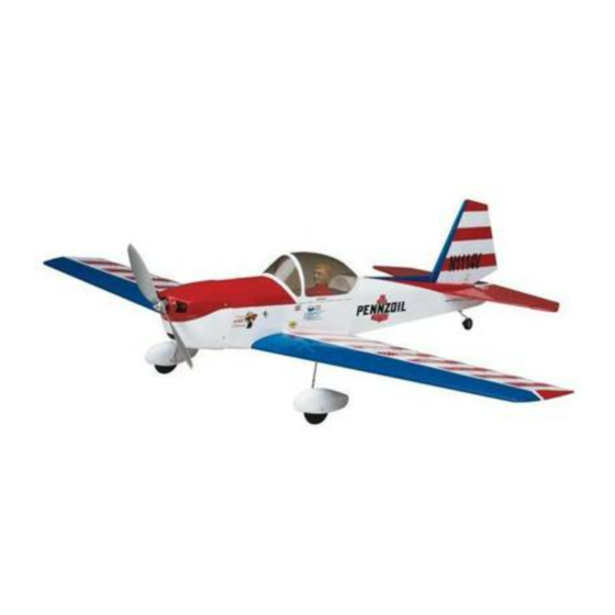
Wingspan: 38 in [965mm]
Wingspan: 38 in [965mm]
Wing Area: 242 in
Wing Area: 242 in
2
2
[15.6dm
[15.6dm
Weight: 23-25 oz [650-710g]
Weight: 23-25 oz [650-710g]
Wing Loading: 13.7-14.8 oz/ft
Wing Loading: 13.7-14.8 oz/ft
Length: 28 in [710mm]
Length: 28 in [710mm]
Radio: 4-Channel with four micro servos
Radio: 4-Channel with four micro servos
Electric Motor: RimFire
Electric Motor: RimFire
™
™
400 (28-30-950kV)
400 (28-30-950kV)
ESC: 25A brushless
ESC: 25A brushless
2
2
]
]
2
2
2
2
[42-45 g/dm
[42-45 g/dm
]
]
Advertisement
Table of Contents

Related Manuals for Carl Goldberg Products Super Chipmunk 400 ARF


Summary of Contents for Carl Goldberg Products Super Chipmunk 400 ARF
- Page 1 ® Wingspan: 38 in [965mm] Wingspan: 38 in [965mm] Wing Area: 242 in Wing Area: 242 in [15.6dm [15.6dm Weight: 23-25 oz [650-710g] Weight: 23-25 oz [650-710g] Wing Loading: 13.7-14.8 oz/ft Wing Loading: 13.7-14.8 oz/ft [42-45 g/dm [42-45 g/dm Length: 28 in [710mm] Length: 28 in [710mm] Radio: 4-Channel with four micro servos Radio: 4-Channel with four micro servos...
-
Page 2: Table Of Contents
TABLE OF CONTENTS ADDITIONAL ITEMS REQUIRED RADIO SYSTEM ADDITIONAL ITEMS REQUIRED ........2 The Chipmunk 400 ARF requires a four-channel radio with a Radio System ..............2 small receiver that will fi t into available space in the fuselage Batteries and Charger ............2 not already occupied by the battery. -
Page 3: Adhesives & Building Supplies
™ Great Planes 8x6 Power Flow Slo-Flyer Elec Prop (pkg. of 2, GPMQ6610) ® (1 pkg) Great Planes adhesive-back Velcro PREPARATION (GPMQ4480) Double-sided foam mounting tape (GPMQ4440) 1. Lay three or four Stick-on segmented lead weights (GPMQ4485) paper towels over each Great Planes 3/8"x3"... -
Page 4: Assemble The Wings
ASSEMBLE THE WINGS JOIN THE AILERONS AND MOUNT THE SERVOS 4. Connect a 6" [150mm] servo extension to one of your aileron servos. Use a piece of Great Planes 3/8" x 3" [10 x 80mm] heat shrink tubing (GPMM1060, not included) cut in half (or tape or other suitable clips intended for this purpose) to secure the servo plugs so they cannot accidentally become disconnected. -
Page 5: Hook Up The Ailerons
the aileron pushrod wire will fi t. Drill 5/64” [2mm] (or 3/32” 7. Mount your other aileron servo in the other wing the [2.4mm]) holes through the aileron for the horn mounting same way. screws and hook up the aileron as shown—note in the photo HOOK UP THE AILERONS that the horn is located on the aileron so the pushrod will be perpendicular to the wing trailing edge and the servo arm. -
Page 6: Mount The Wheels And Landing Gear
MOUNT THE WHEELS AND LANDING GEAR 1. Insert the right and left main landing gear wires into the wing so they will be angled forward. 3/32" [2mm] 3/32" [2mm] 2. Without using any glue, test fi t the wing halves together with the plywood wing joiner. -
Page 7: Assemble The Fuselage
Now you can mount the wheel pants… 1. Use a hobby knife with a sharp blade to cut the covering from the fuselage over the exit slot for the elevator pushrod 5. Use a hobby knife to chamfer the top of the hole on the guide tube (located just under the leading edge of the slot inside of both wheel pants so it will fi... - Page 8 7. Once the stab is centered, stick pins into the trailing edge tightly to both sides of the fuselage, holding the trailing 4. Test fi t the joiner wire and make sure it goes all the way edge in place. into both elevators.
- Page 9 along the string until the arrow aligns with one end of the ink with a few of your paper towel squares dampened with stab. Swing the string over to the same spot on the other side denatured alcohol. of the stab to see if the distances are equal as shown in the sketch.
-
Page 10: Hinge The Elevators And Rudder
HINGE THE ELEVATORS AND RUDDER as shown. Once you get the gear up into position through the slot in the horizontal stab turn it around the other way as shown. 3. The same as was done for the horizontal stabilizer, fi t the vertical stabilizer (fi... -
Page 11: Hook Up The Elevator And Rudder
the rudder the same way the horns were mounted to the ailerons (by drilling 5/64" [2mm] or 3/32" [2.4mm] holes for the screws and mounting the horn with two 2 x 10mm machine-thread Phillips screws and the horn mounting plate on the other side). -
Page 12: Mount The Motor And Esc
90˚ 90˚ 6. Connect the servos to your receiver and power up the system with the trims on the transmitter centered. Fit the servo arms on the servos so they will be as close to 90 2. Fit, then glue the plywood ESC mounting plate degrees as possible to the pushrods (but they don’t have to into position. - Page 13 so in the correct direction when you advance the throttle stick. If necessary, reverse the servo direction for the throttle channel (to get the motor to turn when you advance the throttle). If the motor turns, but in the wrong direction, switch any two motor wires with each other connected to the ESC.
-
Page 14: Mount The Battery And Receiver
MOUNT THE BATTERY AND RECEIVER 4-1/2" [110mm] 1" “HOOK” SIDE [25mm] 3-1/2" [90mm] “LOOP” SIDE 3. Connect the servo wires and a dual aileron extension wire to the receiver. Use double-sided foam mounting tape to mount the receiver where desired. If your receiver is small 1. -
Page 15: Get The Model Ready To Fly
3. Drill 1/16" [1.6mm] holes through the bot- tom of the pilot 1-1/8" [29mm] apart to align with the holes in the bottom of the cockpit fl oor for the pilot mount- ing screws. 4. Use the transmitter to move the elevator up and move the ruler forward so it will still be touching the trailing edge. -
Page 16: Balance And Mount The Propeller
BALANCE AND MOUNT THE PROPELLER 1. If using a Great Planes C.G. Machine to balance the Chipmunk, set the rulers to 2.5" [63mm]. If not using a C.G. 1. For optimum performance and motor effi ciency, Machine, use a fi ne-point felt-tip pen to draw short lines balance the propeller using a Top Flite Precision Magnetic marking the balance point on the top of the wing 2.5"... -
Page 17: Balance The Model Laterally
FLYING The Carl Goldberg Chipmunk 400 ARF is a great-fl ying model that fl ies smoothly and predictably. The Chipmunk does not, however, possess the self-recovery characteristics of a primary R/C trainer and should be fl own only by R/C pilots who have some experience. -
Page 18: Flight
FLIGHT One fi nal note about fl ying your Chipmunk. Have a goal or fl ight plan in mind for every fl ight. This can be learning a new Continue to fl y around for a minute while getting used to how maneuver(s), improving a maneuver(s) you already know, the Chipmunk responds. - Page 20 www.carlgoldbergproducts.com ® Entire Contents © 2012 Hobbico, Inc. All rights reserved. GBGA1023...
Need help?
Do you have a question about the Super Chipmunk 400 ARF and is the answer not in the manual?
Questions and answers