Table of Contents
Advertisement
Quick Links
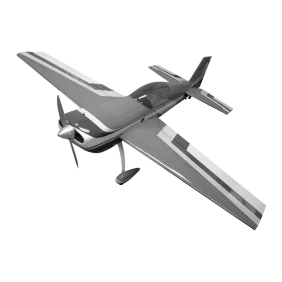
Extra 330 ARF
Extra 330 ARF
A radio-controlled model is not a toy and is not intended for persons under 16 years old. Keep
this kit out of the reach of younger children, as it contains parts that could be dangerous. A radio-
controlled model is capable of causing serious bodily injury and property damage. It is the buyer's
responsibility to assemble this aircraft correctly and to properly install the motor, radio, and all other
equipment. Test and fly the finished model only in the presence and with the assistance of another
experienced R/C flyer. The model must always be operated and flown using great care and common
sense, as well as in accordance with the Safety Code of the Academy of Model Aeronautics (5151
Memorial Drive, Muncie, IN 47302, 1-800-435-9262). We suggest you join the AMA and become prop-
erly insured prior to flying this model. Also, consult with the AMA or your local hobby dealer to find an
experienced instructor in your area. Per the Federal Communications Commission, you are required
to use only those radio frequencies specified "for Model Aircraft."
Carl Goldberg Products, Ltd. has inspected and certified the components of this aircraft. The company urges the buyer to per-
form his own inspection, prior to assembly, and to immediately request a replacement of any parts he believes to be defective for
their intended use. The company warrants replacement of any such components, provided the buyer requests such replacement
within a period of 90 days from the date of purchase and provided the defective part is returned, if so requested by the company.
No other warranty, expressed or implied, is made by the company with respect to this kit. The buyer acknowledges and under-
stands that it is his responsibility to carefully assemble the finished flying model airplane and to fly it safely. The buyer hereby
assumes full responsibility for the risk and all liability for personal or property damage or injury arising out of the buyer's use of the
components of this kit.
CARL GOLDBERG PRODUCTS, LTD.
P.O. Box 818 Oakwood GA 30566 Phone #678-450-0085 Fax # 770-532-2163 www.carlgoldbergproducts.com
©copyright 2004
WARNING
LIMITED WARRANTY
Advertisement
Table of Contents

Related Manuals for Carl Goldberg Products EXTRA 330 ARF


Summary of Contents for Carl Goldberg Products EXTRA 330 ARF
- Page 1 LIMITED WARRANTY Carl Goldberg Products, Ltd. has inspected and certified the components of this aircraft. The company urges the buyer to per- form his own inspection, prior to assembly, and to immediately request a replacement of any parts he believes to be defective for their intended use.
- Page 2 Congratulations on your purchase of the Extra Before beginning assembly of your Extra 330ARF. This is a very unique dual-purpose air- 330ARF, we highly recommend that you study craft, capable of flying any FAI pattern this manual in its entirety. You should begin sequence with ease, while exhibiting remark- planning your radio installation based on your able 3-D capabilities.
- Page 3 A fan is recommended. Also, special care must be taken when using CA, as it will bond skin as well as other NOTE: The Extra 330 ARF covering closely surfaces. Before using any CA, carefully read all label pre- matches Bright Yellow (#872), Flame Red cautions.
-
Page 4: Wing Assembly
WING ASSEMBLY Select the aileron for the wing half on which AILERON INSTALLATION you are working. Collect the following parts: Mix up a liberal amount of 30 minute epoxy. (1) Left wing Working with 1 hinge at a time, place a dab of (1) Right wing epoxy and insert the hinge half way into one of (1) Left aileron... -
Page 5: Aileron Control Horn Installation
Pull the second half of the “Y” harness out Attach the 24” “Y” harness to one of the servos. the inner servo hole. IMPO RTANT! To ensure that any connections locat- Plug the second aileron servo into the wire ed inside the wing will not come loose, either when harness. - Page 6 Caution: Make sure each snap link is fully closed and a clip is installed before and after each flight. Mounting Stab Collect the following parts: Position the control horn bolt so that it is 1/2” (1) Left Stabilizer back from the hinge line on the mark that you (1) Right Stabilizer just made.
-
Page 7: Hinging The Elevators
Gluing Stabilizer: Take the elevators and the stabilizers and just like you did for the ailerons pre-drill each of then hinge holes. 1. Using a pencil, make an outline where the stabilizer rest against the fuselage. Place a drop of oil on each of the hinges. Mix up some 30 minute epoxy and glue each 2. - Page 8 Thread on to each end of the 4-40 x 3-1/2” pushrod a hex nut and a metal clevis. Install the metal clevis onto the horn bracket Plug the 24” extensions into the elevator ser- and the servo arm. tighten the hex nut against vos.
-
Page 9: Rudder Servo
Thread the 2 white adjustable horn brackets on the rod. Do this on both sides of the bolt. Twist the end of the spring on to the horn bracket. Insert the long wire end around the second horn bracket. Twist the wire so that it will stay hooked to the bracket. - Page 10 Remove the cables from the servo tray. Remove the top canopy hatch. Reach down inside the fuselage and pull the cables slowly Insert the cable through the brass tube and froward. then through the hole on the end of the rigging couplers.
- Page 11 INSTALLING MAIN LANDING GEAR Collect the following items: (4) 3mm x 15 phillips Head Screw (4) 3mm Lock Nut (1) Main Aluminum Landing Gear Remove the landing gear cover from the bot- 1. Mount the axle to the landing gears. tom of the fuselage.
-
Page 12: Engine Installation
Landing Gear Wheel Pant Wheel Collars Wheel Keeping the engine perpendicular to the table 7. Mount the wheel pants back on the landing top, clamp the other motor mount to the gear along with the wheel collars and wheels. engine. Mark and drill the second motor mount then screw the mount to the engine. -
Page 13: Engine Throttle Installation
ENGINE THROTTLE INSTALLATION Collect the following items: (1) 1/8” x 16” nylon tubing (1) .072 x 18” Threaded Rod (1) EZ connector (1) Snap Nut (1) 4-40 x 1/8 Screw (1) Nylon Snap Link Thread the nylon snap link onto the wire. Attach the thread link to the servo arm. -
Page 14: Installing The Fuel Tank
Insert the brass tubes through three of the holes. They should be arranged so as the long one will be on the right side of the plane and Attach the three pieces of 5mm tubing to the the short one on the left side. three tank outlets. -
Page 15: Cowl Installation
RECEIVER, BATTERY & SWITCH We placed our receiver in front of the rudder servo and our 1200 Mah battery beside the fuel tank. The location of these items will vary with the engine used. Place the hatch cover over the motor box. Drill holes thought the hatch into the ends of the motor box sides. - Page 16 Bolt the wing to the fuselage using a 1/4-20 nylon bolt. Good Luck and I hope you enjoy flying HATCH & CANOPY the Extra 330 ARF. Gather the following items (1) Canopy Hatch (4) 4-40 x 1/2” Socket Head Bolt...
- Page 17 FLYING YOUR EXTRA 330 ARF FIELD KIT CHECKLIST PRE-FLIGHT ACTIVITIES Fully-charged flight batteries Prior to going to the flying field, with radio batteries Radio transmitter fully charged, turn on both receiver (Rx) and trans- mitter (Tx) and actuate all controls many times until 1 ½...
Need help?
Do you have a question about the EXTRA 330 ARF and is the answer not in the manual?
Questions and answers