Table of Contents
Advertisement
Quick Links
Advertisement
Table of Contents

Related Manuals for Lightware DA2DVI-Pro


Summary of Contents for Lightware DA2DVI-Pro
- Page 1 DA2DVI-Pro User's Manual...
- Page 2 Page 2 / 43...
-
Page 3: Safety Instructions
DA2DVI-Pro User’s Manual Rev. 1.3 SAFETY INSTRUCTIONS Class II apparatus construction. This equipment should be operated only from the power source indicated on the product. To disconnect the equipment safely from power, remove the power cord from the rear of the equipment, or from the power source. -
Page 4: Declaration Of Conformity
DECLARATION OF CONFORMITY Lightware Kft. 1071 Budapest Peterdy str. 15 HUNGARY as manufacturer declare, that the products DA2DVI-Pro ( Video Distribution Amplifier ) in accordance with the EMC Directive 2004/108/EC and the Low Voltage Directive 2006/95/EEC is in conformity with the following standards: EMI/EMC ........ -
Page 5: Table Of Contents
WITCHING THE 2.4. EDID ....................16 ACTORY PRESET LIST FRONT PANEL CONTROL - DIP SWITCH SETTINGS .............. 17 SOFTWARE CONTROL – USING LIGHTWARE MATRIX CONTROLLER ....... 18 4.1....................18 STABLISHING THE CONNECTION 4.2. – I ................. 19 ONTROL MENU NPUT AND OUTPUT STATES 4.3. - Page 6 6.3....................... 37 HERE IS NO INPUT SIGNAL MECHANICAL DRAWINGS ......................38 7.1..........................38 RONT VIEW 7.2..........................38 EAR VIEW 7.3..........................39 OP VIEW 7.4.......................... 40 OTTOM VIEW WARRANTY ..........................41 SPECIFICATIONS ........................42 Page 6 / 43...
-
Page 7: General Description
+5V 500 mA constant current output on each DVI OUTPUT to power long distance fiber optical cables. Universal power adaptor – DA2DVI-Pro is equipped with a universal +5V power adaptor, which accepts AC voltages from 100 to 240 Volts with 50 or 60 Hz line frequency. -
Page 8: Advanced Edid Management
The EDID emulated on the input can be copied from the DA2DVI-Pro's memory (static EDID emulation) or from the attached monitor (dynamic EDID emulation). For example, the DA2DVI-Pro can be set up to emulate the device, which is connected to DVI OUTPUT 1, and the EDID automatically changes, if the monitor is replaced with another display device (as long as it has a valid EDID). - Page 9 DA2DVI-Pro User’s Manual Rev. 1.3 Inter-pair skew: skew between two differential wire pairs in a cable. It’s caused by different wire pair lengths or different number of twists in the DVI cable. Too much inter-pair skew results in color shift in the picture or sync loss.
-
Page 10: Fiber Cable Powering
1.5. Fiber Cable powering As special feature DA2DVI-Pro is able to supply 500 mA current to power fiber optical transmitters like DVI-OPT-TX100 (Pin 14 on both DVI output connectors). Standard DVI outputs or VGA cards supply only 55 mA current on +5V output, thus unable to directly power a fiber optical cable. -
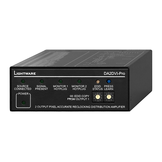
Page 11: Front And Rear View
Status LEDs Learn EDID button Power LED Address selection Source connected LED Indicates if a DVI source is connected to the DA2DVI-Pro, it is powered on and sends +5V signal to Pin 14 of the input DVI connector. Signal present LED Indicates if a valid DVI clock signal is present on the input DVI connector. -
Page 12: Rear Panel View
USB connector USB Type B female connector for remote control using Lightware Matrix Controller software. Connect a USB Type A/B cable between the DA2DVI-Pro and the controlling PC or laptop. +5V DC connector Connect the output of the supplied +5V power adaptor. -
Page 13: Electrical Connections
User’s Manual Rev. 1.3 1.8. Electrical connections 1.8.1. DVI inputs and outputs DA2DVI-Pro provides 29 pole „digital only” DVI-I connectors for input and output connections. Always use high quality DVI cable for connecting sources and displays. The input has a built-in signal detection circuit with a LED indicator located on the front panel. -
Page 14: Usb Control Port
Connect a USB Type A/B cable between the DA2DVI-Pro and the controlling PC or laptop. Please make sure not to send any commands to the DA2DVI-Pro via the USB port until it has finished the booting process (EDID Status LED continuously illuminated green or red). -
Page 15: Operation
If GREEN, the memory was already used before, but still available for programming. Push the LEARN button on the front side of the DA2DVI-Pro and hold it down for approximately 3 seconds. Once the button is pushed the EDID status LED goes dark. If the storing was successful, the GREEN EDID status LED blinks five times and stays illuminated. -
Page 16: Switching The Edid
Monitor output then the EDID provided on the DVI INPUT connector is the EDID of the last connected monitor. Info If an invalid EDID is selected, the DA2DVI-Pro does NOT transmit a HOT PLUG signal to the source connected to the DVI INPUT. Info After every EDID change, DA2DVI-Pro toggles the HOT PLUG signal for approximatley 1 second. -
Page 17: Front Panel Control - Dip Switch Settings
Advanced users can make adjustments using an 8 circuit DIP switch located on the rear panel of the DA2DVI-Pro (see chapter 1.7.2). SW 1: defines whether the DA2DVI-Pro is controlled by the rotary switches and the DIP switch or the Lightware... -
Page 18: Software Control - Using Lightware Matrix Controller
Turn DIP Switch 1 in ON position to enable USB control function. Info USB Connection to the DA2DVI-Pro can be done even if it’s in front panel control mode, but only the status of the settings can be checked, and no software changes can be applied. -
Page 19: Control Menu - Input And Output States
(crosspoint area) appears according to the input and output numbers of the device. For DA2DVI-Pro, I1 column represents the input, O1 and O2 rows represent the outputs. Regardless of the fact that a crosspoint switching area appears, the input signal is always routed to both outputs by default. -
Page 20: Edid Menu
When the user enters the menu for the first time, the software starts to download the whole EDID content from the DA2DVI-Pro. It may take about 10-20 seconds. After the list is downloaded, the current status of the EDID list is shown in two windows (list window areas). - Page 21 Drag and drop the selected EDID to the desired User Memory location. Load EDID from file to memory The DA2DVI-Pro is able to learn and store EDID from a file located on the computer. EDID are stored in *.dat files.
-
Page 22: Advanced Edid Editor
When the user enters the menu for the first time, an empty EDID is loaded into the editor’s memory. All EDID in the DA2DVI-Pro’s memory can be edited in the following way: Right click on the desired EDID to be loaded to the EDID Editor. -
Page 23: Status Menu
DA2DVI-Pro User’s Manual Rev. 1.3 4.5. STATUS menu Basic device information, such as device name, firmware version, the input and output cards’ hardware revisions are displayed in this window. 4.6. Find menu By selecting this menu option, the available devices can be rescanned on the COM ports and on the Ethernet. -
Page 24: Output Settings
4.7. Output Settings A right click on the output port label (O1 or O2) near the crosspoint field will open the Set DVI parameters window. Apply changes to Current output: this option means the modified parameters are applied only to the currently selected port displayed in the header. - Page 25 De-skewing SW 4, 5 and 6 of the DIP switch adjust this value on the rear panel of the DA2DVI-Pro. If the clock and pixel data are not perfectly aligned in the internal parallel signal, then there’s a possibility to add some skew between them in both directions.
-
Page 26: Control Commands
4.8. Control commands An arrow prefix pointing from left to right (→) indicates a command given to the DA2DVI-Pro, and an arrow prefix pointing from right to left (←) indicates a response given by the DA2DVI-Pro. 4.8.1. View product type Description: The DA2DVI-Pro responds its name. -
Page 27: Route Edid To The Input (Dynamic)
Info: DVI OUTPUT 1 is mapped to logical address 101. After choosing dynamic EDID routing for the input, the DA2DVI-Pro will follow the EDID changes that occur on DVI OUTPUT 1. 4.8.6. Save EDID from output to memory location (Learn EDID) Description: Learn EDID from <out>... -
Page 28: View Edid Validity Table
1600x1200@60 Display device’s name: 60 LCD2170NX 4.8.9. Upload EDID content from the DA2DVI-Pro Description: EDID hex bytes can be read directly. The DA2DVI-Pro will issue the whole content of the EDID present on memory location <loc> (256 bytes). Format: {we<loc>} →... -
Page 29: Download Edid Content To The Da2Dvi-Pro
Send 1 block of EDID (1 block consist of 8 bytes of hex data represented in ASCII format) {WB#1●B1●B2●B3●B4●B5●B6●B7●B8} The DA2DVI-Pro acknowledges (EL#●) Send another 31 blocks of EDID (32 altogether) After the last acknowledge, the DA2DVI-Pro signals that the EDID status has changed (E_S_C) CrLf Format: → {WL#<loc>} ←... -
Page 30: Da2Dvi-Pro Initiated Commands
OUTPUT 1. After disconnecting this device, its EDID will still be present in the DA2DVI-Pro’s memory, therefore no status change message is issued by the DA2DVI-Pro if a display device having the same EDID is connected to that output. (The same display device is connected again, or another display device (same... -
Page 31: Input And Output Port Status
DA2DVI-Pro User’s Manual Rev. 1.3 Front panel control Description: The DA2DVI-Pro is set to be controlled via the USB port by SW1 of the DIP switch. Format: ← (NOK)CrLf 4.10. Input and output port status 4.10.1. Check the status of the inputs Description: Use this command to determine the actual status of the input port. -
Page 32: Firmware Upgrade
Firmware upgrade The DA2DVI-Pro’s firmware can be upgraded via USB. Step 1. Connect a USB Type A/B cable between the PC and the DA2DVI-Pro. Run the bootloader software on the controlling computer. Page 32 / 43... - Page 33 You must wait until every device boots up completely before pressing FIND button. Step 3. Double click on the COM port that the DA2DVI-Pro is connected to. The bootloader cannot identify the devices on the COM ports so if you are unsure about which virtual COM port the DA2DVI-Pro is connected to, run the Matrix Controller software and check.
- Page 34 Now you can browse for the new firmware file to upload. Step 5. To enable the upgrade, you need to check the checkbox next to the DA2DVI-Pro’s name. Now click on the UPGRADE SELECTED FIRMWARES button and select YES in the pop-up window.
- Page 35 DA2DVI-Pro User’s Manual Rev. 1.3 Step 6. If the upgrade was completed without errors, the bootloader displays an Upgrade Successful message. After clicking on OK button, you can close the connection by exiting the bootloader or select another device to upgrade.
-
Page 36: Troubleshooting
Check the incoming signal Check the Source Connected LED on the front panel of the DA2DVI-Pro. This LED indicates the presence of the +5V signal coming from the DVI source. If it is not illuminated, then your DVI source is not working properly. -
Page 37: There Is No Input Signal
DA2DVI-Pro User’s Manual Rev. 1.3 6.3. There is no input signal Check the source Check whether your source is powered on and configured properly. If the source is a computer, then verify that the DVI output is selected and active. Try restarting your computer;... -
Page 38: Mechanical Drawings
Mechanical Drawings 7.1. Front view 42 mm 110 mm 7.2. Rear view 42 mm 110 mm Page 38 / 43... -
Page 39: Top View
DA2DVI-Pro User’s Manual Rev. 1.3 7.3. Top view 180 mm 110 mm Page 39 / 43... -
Page 40: Bottom View
7.4. Bottom view 2x M3 thread 87 mm 21,25 mm 21,25 mm For rack mounting, cross recessed M3 (max 10 mm long) screws must be used. Page 40 / 43... -
Page 41: Warranty
Lightware Visual Engineering warrants this product against defects in materials and workmanship for a period of three years from the date of purchase. The customer shall pay shipping charges when unit is returned for repair. Lightware will cover shipping charges for return shipments to customers. -
Page 42: Specifications
Specifications Video Standard ....................DVI 1.0 Color depth ................24 bits, 8 bit/color Format ..................... RGB only Data rate ........... all between 25 Mbps and 1.65 Gbps /color Resolutions (single link) ....all between 640x480 and 1920x1200@60Hz HDTV resolutions ..............720p, 1080i, 1080p HDCP compliant .................... - Page 43 DA2DVI-Pro User’s Manual Rev. 1.3 NOTES: Page 43 / 43...
Need help?
Do you have a question about the DA2DVI-Pro and is the answer not in the manual?
Questions and answers