Table of Contents
Advertisement
Quick Links
Advertisement
Table of Contents

Related Manuals for Falcon E9042


Summary of Contents for Falcon E9042
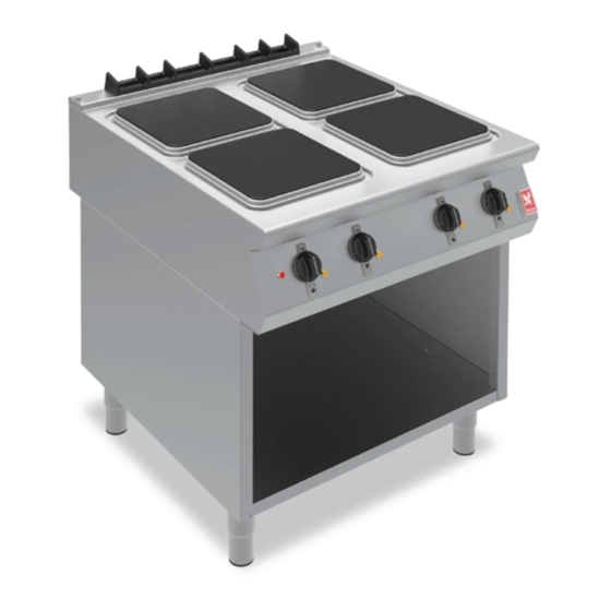
- Page 1 F900 SERIES User, installation and servicing instructions HOTPLATE COUNTERTOP AND OVEN RANGE E9042, E9084, E9184 Read these instructions before use DATE PURCHASED: MODEL NUMBER: SERIAL NUMBER: DEALER: SERVICE PROVIDER: T100944 REV 6 Published: 01-09-2017...
- Page 2 Dear Customer, Thank you for choosing Falcon Foodservice Equipment. This manual can be downloaded from www.falconfoodservice.com or scan here. IMPORTANT: Please keep this manual for future reference. Falcon Foodservice Equipment HEAD OFFICE Wallace View, Hillfoots Road, Stirling. FK9 5PY. Scotland.
- Page 3 SYMBOLS. • • SCREWDRIVER • COOKING OIL •GREASE SPANNER • • FLAME • WARNING • VIEWPORT SPARK IGNITION • •IGNITER •C SPANNER ALLEN KEY...
- Page 4 We recommend supplementary electrical protection with the use of a residual current device (RCD) The appliance has been designed and approved to use Falcon Kick plates, non Falcon kick plates could potentially adversely affect the performance of the appliance by restricting the air to the appliance.
- Page 5 CONTENTS APPLIANCE INFORMATION ..................6 OPERATION ......................7 COMPONENT PARTS .................... 7 CONTROLS ......................8 USING THE APPLIANCE ..................9 CLEANING AND MAINTENANCE ................10 HOB ........................10 OVEN ........................10 FLUE CAPPER ..................... 11 SPECIFICATION ...................... 12 DIMENSIONS / CONNECTION LOCATIONS ............13 INSTALLATION ......................
-
Page 6: Appliance Information
APPLIANCE INFORMATION This appliance has been CE-marked on the basis of compliance with the relevant EU directives for the heat inputs, gas pressures and voltages stated on the data plate. A - Serial No B - Model No C - Flue Type D - Gas Category E - Gas Pressure F - Gas Type... -
Page 7: Operation
2.0 OPERATION 2.1 COMPONENT PARTS A - Hotplate zone control B - Oven zone control C - Oven temperature control D - Hotplate E - Flue capper F - Drip tray G - Door H - Shelf... -
Page 8: Controls
2.2 CONTROLS A – Power neon (red) B – Hotplate zone Indicator C – Hotplate heat neon (amber) D – Oven indicator E – Oven temperature indicator F – Oven heat neon (amber) -
Page 9: Using The Appliance
USING THE APPLIANCE 2.3.1 Before use, clean the appliance hob. See section 3. 2.3.2 Switch hotplate control to required setting (A). 2.3.3 To switch off hotplates turn control knob to off position. 2.3.4 Switch oven zone control knob (B) to required setting. 2.3.5 Use temperature control knob (C) to adjust temperature…... -
Page 10: Cleaning And Maintenance
3.0 CLEANING AND MAINTENANCE BEFORE ANY CLEANING IS FAILURE TO CLEAN THIS UNDERTAKEN, ISOLATE WILL BE DETRIMENTAL TO APPLIANCE FROM MAINS THE PERFORMANCE OF THE POWER SUPPLY AT HOTPLATE & OVEN. ISOLATOR SWITCH. 3.1.1 At the end of each day or cooking period, turn off appliance and let it cool down. 3.1.2 Remove any trivet plates if used. -
Page 11: Flue Capper
3.2.2 Turn off and let oven cool down. 3.2.3 Remove base tray, base plate and shelf hangers. 3.2.4 Clean oven chamber using soap and water. 3.2.5 Clean shelves and base tray using soap and water. FLUE CAPPER 3.3.1 The flue capper can be removed for cleaning but must be replaced for use. -
Page 12: Specification
4.2.3 This appliance must be EARTHED. Live 1 ( Phase 1) Brown Live 2 ( Phase 2) Black Live 3 ( Phase 3) Grey Neutral Blue Earth Yellow/Green E9042 Phase Actual (A) 16.3 19.0 17.3 16.3 19.0 17.3 E9084 Phase Actual (A) 32.5... -
Page 13: Dimensions / Connection Locations
5.0 DIMENSIONS / CONNECTION LOCATIONS A = ELECTRICAL INLET... -
Page 14: Installation
6.0 INSTALLATION SITING / CLEARANCES Where this appliance is to be positioned in close proximity to a wall, partitions, kitchen furniture, decorative finishes, etc., it is recommended that they be made of non-combustible material; if not, they shall be clad with a suitable non-combustible heat insulating material, and that the closest attention be paid to fire prevention regulations. -
Page 15: Commissioning
COMMISSIONING 6.3.1 Remove rear hatch 6.3.2 Connect appliance to mains supply 6.3.3 Refer to section 2.3 or 2.4 for operation. 6.3.4 This appliance is also provided with a terminal for connection of an external equipotential conductor. This terminal is an effective electrical contact with all fixed exposed metal parts of the appliance, and shall allow the connection of conductor having a nominal cross-section area of up to 10mm². -
Page 16: Suiting
The DLS system is designed to give a quick and easy suiting solution. If you require an improved seal between appliances we recommend you use, a food grade, high temperature silicon sealant. This can be supplied by Falcon Part No – 523400021 6.4.6 6.4.7 Apply... -
Page 17: Suiting
6.4.8 Slide suited units into position. 6.4.9 (A) Right hand unit: Screw the M5 x 40 screw (supplied in the kit) into one of the suiting plates as shown and then insert through the front fixing holes of both units. 6.4.9 (B) Left hand unit: Slide the penny and lock washer on to the screw and secure using the M5 nut. -
Page 18: Servicing
7.0 SERVICING CONTROL PANEL REMOVAL 7.1.1 Remove as shown. OPERATING THERMOSTAT REMOVAL 7.2.1 Remove operating thermostats as shown (only on E9184 model). -
Page 19: Safety Thermostat Removal
SAFETY THERMOSTAT REMOVAL 7.3.1 Undo screws on base access plate (only on E9184 model). 7.2.1 Remove safety thermostat as shown (only on E9184 model). -
Page 20: Hotplate Removal
HOTPLATE REMOVAL 7.4.1 Remove cover plates as required (only on E9184 model). 7.4.2 Undo hotplate centre fixing nut(s) and disconnect hotplate wiring at terminal bracket (A) as appropriate. - Page 21 7.4.3 Lift-off hotplate as required. 7.4.4 When re-fitting hotplate, ensure seal has been fitted into groove of spill ring.
-
Page 22: Top Element Removal
7.4.5 Once the hotplate is sitting on the hob and the locating screw is through centre hole in the hotplate support assembly, carefully align and centralise the hotplate. Refit the centre fixing nut and re-tighten. This will pull down the hotplate centrally and equally. Do not adjust the four corner screws that the hotplate sits on (these are only for additional support and not for levelling). -
Page 23: Bottom Element Removal
BOTTOM ELEMENT REMOVAL 7.6.1 Remove base shelves as required. 7.6.2 Remove screws from element fixing plate as required. 7.6.2 Disconnect wires and remove element from oven. -
Page 24: Circuit Diagrams
CIRCUIT DIAGRAM’S:... -
Page 28: Wiring Diagrams
WIRING DIAGRAM’S:... -
Page 32: Oven Door Removal
OVEN DOOR REMOVAL THE HINGE SPRING IS UNDER TENSION AND NO ATTEMPT SHOULD BE MADE TO REMOVE THE PINS WHEN THE DOOR IS OFF. 8.1.1 Turn off and cool down. 8.1.2 Open the door fully and push an Ø4mm pin into the hole on each hinge. 8.1.3 Holding the door with both hands half way down each side, rotate and lift up until the hinge hits the top of the hinge aperture. -
Page 33: Accessories
Call Engineer 11 SPARE PARTS Oven top element 733440003 Oven bottom element 730962060 Hotplate 4.4kw 733400001 Hotplate seal 733400002 Control panel E9042 733400003 Control panel E9084 733410000 Control panel E9184 733440004 Power neon red 730962010 Heat demand neon amber 730962040... -
Page 34: Service Information
12 SERVICE INFORMATION It is recommended to have a maintenance contract with a local service provider. SERVICELINE CONTACT: (UK only) Phone: +441438 363 000 Warranty Policy Shortlist For our warranty policy please go to www.falconfoodservice.com...
Need help?
Do you have a question about the E9042 and is the answer not in the manual?
Questions and answers