Table of Contents
Advertisement
Quick Links
Advertisement
Table of Contents

Related Manuals for Falcon Elise 110 Dual Fuel


Summary of Contents for Falcon Elise 110 Dual Fuel
- Page 1 USER GUIDE & INSTALLATION INSTRUCTIONS Elise 110 Dual Fuel Australia U111114-01...
-
Page 3: Table Of Contents
Contents Before You Start... Installation Personal Safety Location of cooker Electrical Connection Safety Conversion If You Smell Gas Positioning the Range Peculiar Smells Moving the cooker Cooling Fan Lowering the two rear rollers Ventilation Completing the move Maintenance Levelling Grill/Glide-out Grill™ Care Fitting the stability bracket or chain Cooker Care Repositioning the cooker following... -
Page 5: Before You Start
Before You Start... Your cooker should give you many years of The cooker should not be placed on a base. • trouble-free cooking if installed and operated This appliance is designed for domestic • correctly. It is important that you read this cooking only. -
Page 6: Electrical Connection Safety
Always keep combustible materials, e.g. Make sure that the gas supply is turned • • curtains, and flammable liquids a safe on and that the cooker is wired in and distance away from the cooker. switched on. DO NOT spray aerosols in the vicinity of In your own interest and that of safety, it is •... -
Page 7: Ventilation
NEVER leave the hotplate unattended Ventilation • at high heat settings. Pans boiling over The use of a cooking appliance results in the can cause smoking, and greasy spills may production of heat and moisture in the room catch on fire. Use a deep fat thermometer in which it is installed. - Page 8 DO NOT modify this appliance. This • Fig. 1.1 appliance is not intended to be operated by means of external timer or separated remote-control system. If flammable materials are stored in the • ArtNo.324-0001 Steam burst drawer, oven(s) or grill(s) it may explode and result in fire or property damage.
-
Page 9: Grill/Glide-Out Grill™ Care
DO NOT use the timed oven if the Cooker Care • adjoining oven is already warm. As steam can condense to water droplets DO NOT place warm food in the oven to be on the cool outer trim of the oven, it may be •... - Page 10 DO NOT put the burner heads in a • dishwasher. NEVER use caustic or abrasive cleaners as • these will damage the surface. DO NOT use steel wool, oven cleaning • pads or any other materials that will scratch the surface. NEVER store flammable materials in the •...
-
Page 11: Cooker Overview
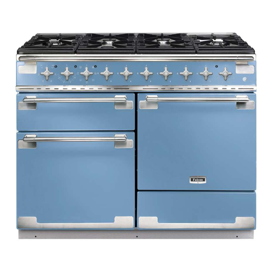
Cooker Overview DocAUS.020-0004 - Overview - 110DF - Elan Fig. 2.1 ArtNo.215-0009 - 110 Elan DF The 110 dual fuel cooker (Fig. 2.1) has the following features: Fig. 2.2 6 hotplate burners including 2 wok burners A control panel A glide-out grill Main multi-function oven Fan oven Storage drawer... -
Page 12: Wok Burner
If, when you let go of the control knob the burner goes out, Fig. 2.3 then the FSD has not been bypassed. Turn the control knob to the OFF position and wait for one minute before you try again, this time making sure to hold in the control knob for slightly longer. -
Page 13: The Wok Cradle
The Wok Cradle Fig. 2.9 The wok cradle is designed to fit a 35 cm wok. If you use a different wok, make sure that it fits the cradle. Woks vary very widely in size and shape. It is important that the wok sits down on the pan support –... -
Page 14: The Ovens
The Glide-out Grill™ (Fig. 2.15) Fig. 2.15 WARNING: When the trivet has been removed from the grill pan, please ensure that the grill pan and cradle are fully returned into the grill chamber. The grill pan door MUST remain open. Accessible parts may be hot when the broiler is in use. - Page 15 Multi-function Oven Functions Fan Assisted Oven This function operates the fan, circulating air heated Defrost by the elements at the top and the base of the oven. This function operates the fan to circulate cold air The combination of fan and conventional cooking only.
-
Page 16: Main Oven Light
The Fan Oven Fig. 2.16 The right-hand oven is a fan oven that circulates hot air continuously, which means faster, more even cooking. The recommended cooking temperatures for a fan oven are generally lower than a conventional oven. NOTE: Please remember that all cookers vary so temperatures in your new ovens may differ to those in your previous cooker. -
Page 17: Accessories
Accessories Fig. 2.21 Oven Shelves Shelf guard The oven shelves (Fig. 2.21) are retained when pulled forward but can be easily be removed and refitted. Pull the shelf forwards until the back of the shelf is stopped by the shelf support (Fig. 2.22). Lift up the front of the shelf so the back of the shelf will pass Front under the shelf stop and then pull the shelf forward... -
Page 18: Using The Glide-Out Grill
Using the Glide-out Grill™ DocAUS.020-0004 - Overview - 110DF - Elan Fig. 3.2 Fig. 3.1 Nearest to the element Middle High Middle Low Furthest from the element Four grill height positions refer to Fig. 3.5 Fig. 3.4 Fig. 3.3 To switch on both elements To switch on the right half element Four grill height positions Fig. -
Page 19: Cooking Tips
English Cooking tips Cooking with a multifunction oven General oven tips Remember: not all modes are suitable for all food types. The The wire shelves should always be pushed firmly to the back oven cooking times given are intended for a guide only. of the oven. -
Page 20: Cooking Table
Cooking Table The oven control settings and cooking times given in the table below are intended to be used as a guide only. Individual tastes may require the temperature to be altered to provide a preferred result. Top (T) ArtNo.050-0007 Centre (C) Food is cooked at lower temperature in a fan oven than in a conventional oven. -
Page 21: Cleaning Your Cooker
Cleaning your cooker Essential information Fig. 6.1 Isolate the electricity supply before carrying out any thorough cleaning. Allow the cooker to cool. NEVER use paint solvents, washing soda, caustic cleaners, biological powders, bleach, chlorine based bleach cleaners, coarse abrasives or salt. DO NOT mix different cleaning products –... -
Page 22: The Griddle Plate (Optional)
The Griddle Plate (optional) Fig. 6.5 ArtNo.331-0003 Grill frame out, no pan Always clean the griddle plate after use. Allow it to cool completely before removing. Immerse the griddle plate in hot soapy water. Use a soft cloth or, for stubborn stains, a nylon washing up brush. -
Page 23: Ovens
Ovens Fig. 6.8 ‘Cook & Clean’ Panels The main oven has panels which have been coated with a special enamel that partly cleans itself. This does not stop all marks on the lining, but helps to reduce the amount of manual cleaning needed. -
Page 24: Cleaning Table
Cleaning table Cleaners listed are available from supermarkets or electrical retailers as stated. For enamelled surfaces use a cleaner that is approved for use on vitreous enamel. Regular cleaning is recommended. For easier cleaning, wipe up any spillages immediately. Hotplate Part Finish Recommended Cleaning Method... -
Page 25: Troubleshooting
Troubleshooting Hotplate/Cooktop ignition or hotplate burners faulty Fig. 7.1 Fig. 7.2 Is the power on? If not, there maybe something wrong with the power supply. Are the sparker (ignition electrode) or burner slots blocked by debris (Fig. 7.1, Fig. 7.2 , Fig. 7.3, Fig. 7.4) ? Are the burner trim and caps correctly located? See the section on ‘Cleaning’... - Page 26 The oven is not cooking evenly Fig. 7.5 Do not use a baking tray with dimensions larger than those specified in the section on ‘General Oven Tips’ . If you are cooking a large item, be prepared to turn it round during cooking.
- Page 27 Grill The fascia gets hot when I use the oven or grill The cooker is cooled by a fan. If the fascia becomes excessively hot when the cooker is in use then the cooling fan may have failed. Should this occur please contact your installer, a qualified repair engineer or Customer Service to arrange for its repair.
-
Page 28: Service And Spares
Please Note For warranty information and how to request a remedy, please refer to the Warranty Statement at www.andico.com.au/customer-care/falcon or contact Customer Care. Out of Warranty We recommend that our appliances are serviced regularly throughout their life to maintain the best performance and efficiency. -
Page 29: Installation
INSTALLATION Check the appliance is electrically safe when you have finished. Installation Location of cooker 4 pan supports Wok cradle The cooker may be installed in a kitchen/kitchen diner but NOT in a room containing a bath or shower. This appliance is designed for domestic cooking only. Use for ArtNo.255-0012 - ArtNo.000-0009 Wok ring, cast 110DF - Elise pan supports... -
Page 30: Positioning The Range
INSTALLATION Check the appliance is electrically safe when you have finished. Positioning the Range Fig. 9.1 The diagram (Fig. 9.1) shows the minimum recommended distance from the cooker to nearby surfaces as given in AS/NZS 5601. Overhead – Measurement A The minimum height of any surface above the cooker is 650 mm above the hotplate. -
Page 31: Moving The Cooker
INSTALLATION Check the appliance is electrically safe when you have finished. When Fitting Between Kitchen Cabinets Fig. 9.2 *Note We recommend that you either: 5mm gap if the appliance is 30mm in front of the kitchen cabinets Fit the range so that any cabinet doors are at least 9mm gap if the appliance is to be flush fitted WORKTOP 30 mm behind the range door fronts. -
Page 32: Completing The Move
INSTALLATION Check the appliance is electrically safe when you have finished. Completing the move Fig. 9.6 Unfold the rear edge of the cardboard base tray. Open the oven door(s) so that you can get a good grip on the bottom of the fascia panel as you move the oven (Fig. -
Page 33: Fitting The Stability Bracket Or Chain
INSTALLATION Check the appliance is electrically safe when you have finished. Fitting the stability bracket or Fig. 9.8 chain Stability chain Unless otherwise stated, a cooker using a flexible gas connector must be secured with a suitable stability device. Suitable stability devices are shown in Fig. 9.8, Fig. 9.9, Fig. -
Page 34: Gas Connection
INSTALLATION Check the appliance is electrically safe when you have finished. Gas Connection Fig. 9.12 This must be in accordance with the relevant standards. The gas supply needs to terminate with a down-facing Gas inlet threaded fitting ½” connection. The inlet connector is located just below the hotplate level at the rear of the cooker. -
Page 35: Electrical Connection
INSTALLATION Check the appliance is electrically safe when you have finished. Turn on the control knob for the burner with the pressure gauge fitted to let gas through. Current Operated Earth Leakage Breakers See the data badge for test pressures. The combined use of your cooker and other domestic appliances may cause nuisance tripping, so we recommend Turn off the burners. -
Page 36: Fixed Wiring
INSTALLATION Check the appliance is electrically safe when you have finished. Fixed Wiring Fig. 9.15 Disconnect from the mains supply. For connection to fixed wiring, i.e. flexible conduit, Remove the electrical terminal cover on the back panel (Fig. 9.15). Remove the M4 screw securing the reducer plates to the conduit box (Fig. -
Page 37: 10. Final Fitting
INSTALLATION Check the appliance is electrically safe when you have finished. 10. Final Fitting Fitting the Handrail Fig. 10.1 Retaining screw Using the 2 mm Allen key supplied, loosen the two retaining screws in the base and side of the handrail support. -
Page 38: 11. Conversion To Lp Gas
WARNING – SERVICING TO BE CARRIED OUT ONLY BY AN AUTHORISED PERSON Disconnect from electricity and gas before servicing. Check appliance is safe when you have finished. 11. Conversion to LP Gas Conversion from Natural Gas Fig. 11.1 (1.0 kPa) to LPG X Propane (2.54 kPa) A suitably competent person must perform the conversion. -
Page 39: Set The Governor
WARNING – SERVICING TO BE CARRIED OUT ONLY BY AN AUTHORISED PERSON Disconnect from electricity and gas before servicing. Check appliance is safe when you have finished. Set the Governor Fig. 11.5 Unscrew the governor’s brass top. In the base of the brass top is a plastic snap-in converter device (Fig. -
Page 40: 12. Servicing
WARNING – SERVICING TO BE CARRIED OUT ONLY BY AN AUTHORISED PERSON Disconnect from electricity before servicing. Check appliance is safe when you have finished. 12. Servicing BEFORE SERVICING ANY GAS CARRYING Fig. 12.1 COMPONENTS TURN OFF THE GAS SUPPLY Check the appliance is gas sound after completion of service. - Page 41 WARNING – SERVICING TO BE CARRIED OUT ONLY BY AN AUTHORISED PERSON Disconnect from electricity before servicing. Check appliance is safe when you have finished. 2 Hotplate Fig. 12.3 2.1 To remove the hotplate BEFORE SERVICING ANY GAS CARRYING COMPONENTS, TURN OFF THE GAS SUPPLY. Screws DISCONNECT FROM THE ELECTRICAL SUPPLY ! Remove the pan supports and burner heads.
- Page 42 WARNING – SERVICING TO BE CARRIED OUT ONLY BY AN AUTHORISED PERSON Disconnect from electricity before servicing. Check appliance is safe when you have finished. Remove the hotplate tray (see 2.1). The burners (except the wok burner) are mounted on support struts. For these burners, disconnect the burner feed pipes at the burner.
- Page 43 WARNING – SERVICING TO BE CARRIED OUT ONLY BY AN AUTHORISED PERSON Disconnect from electricity before servicing. Check appliance is safe when you have finished. 4.2 To Replace the Grill Element Fig. 12.6 DISCONNECT FROM THE ELECTRICITY SUPPLY. Remove the grill pan from the grill chamber. From inside the grill compartment, undo the 2 screws and washers and remove the enamelled front shield from the grill roof.
- Page 44 WARNING – SERVICING TO BE CARRIED OUT ONLY BY AN AUTHORISED PERSON Disconnect from electricity before servicing. Check appliance is safe when you have finished. 5.3 To Change the Fan in the Right-hand Oven Fig. 12.7 DISCONNECT FROM THE ELECTRICITY SUPPLY. Pull the cooker forward to gain access to the rear.
- Page 45 WARNING – SERVICING TO BE CARRIED OUT ONLY BY AN AUTHORISED PERSON Disconnect from electricity before servicing. Check appliance is safe when you have finished. Top Element Fig. 12.10 Fig. 12.11 Open the left-hand oven door and undo the fixings that secure the heat shield.
- Page 46 WARNING – SERVICING TO BE CARRIED OUT ONLY BY AN AUTHORISED PERSON Disconnect from electricity before servicing. Check appliance is safe when you have finished. 6.5 To Change the Oven Door Latch Fig. 12.16 Fig. 12.15 Remove the outer door panel (see 6.4). Remove screws ‘B’ , which hold the latch assembly to the inner door panel (Fig.
-
Page 47: 13. Circuit Diagram
13. Circuit Diagram P095199 P038434 P095199 The connections shown in the circuit diagram are for single-phase. The ratings are for 230 V 50 Hz. Code Description Code Description Code Color Blue Grill Front Switch Right Hand Oven Front Switch Brown Grill Energy Regulator Right Hand Oven Fan Element Black... -
Page 48: 14. Technical Data
Operating Pressure at appliance test point Natural Gas 1 kPa Propane 2.54 kPa Dimensions Model Elise 110 Dual Fuel Overall height minimum 910 mm maximum 935 mm Overall width 1092 mm Overall depth 598 mm excluding handles, 650 mm including handles... - Page 49 NOTE...
- Page 50 NOTE...
- Page 51 NOTE...
- Page 52 Clarence Street, Royal Leamington Spa, Warwickshire, CV31 2AD, England. www.falconworld.com...
Need help?
Do you have a question about the Elise 110 Dual Fuel and is the answer not in the manual?
Questions and answers