
Subscribe to Our Youtube Channel
Related Manuals for Multitech SocketModem Cell HSPA+ MTSMC-H5 Series


Summary of Contents for Multitech SocketModem Cell HSPA+ MTSMC-H5 Series
- Page 1 LEGAL NOTICES AND CONTACT INFORMATION SocketModem® Cell HSPA+ SocketModem® iCell HSPA+ MTSMC-H5 Device Guide SocketModem Cell HSPA and SocketModem iCell HSPA MTSMC-H5 Device Guide...
- Page 2 The Knowledge Base provides immediate access to support information and resolutions for all Multi-Tech products. Visit http://www.multitech.com/kb.go. Support Portal To create an account and submit a support case directly to our technical support team, visit: https://support.multitech.com. Support Business Hours: M-F, 9am to 5pm CT...
-
Page 3: Table Of Contents
CONTENTS Contents Chapter 1 – Device Overview ............................5 Description ..................................5 Product Build Options ................................. 5 Documentation ................................... 6 Chapter 2 – Mechanical Drawing ..........................7 MTSMC-H5 All Builds ................................7 Chapter 3 – Specifications ............................8 Technical Specifications ..............................8 Mounting Hardware ................................9 Recommended Parts .................................. - Page 4 CONTENTS Notice for Devices that Use Aeris Radios .......................... 27 Chapter 6 – Application Notes ..........................28 LED Interface ..................................28 LED 1 – Heartbeat – IP and –GP Builds Only ........................... 28 LED 2 – Link Status – All Builds ................................ 28 LED 3 –...
-
Page 5: Chapter 1 - Device Overview
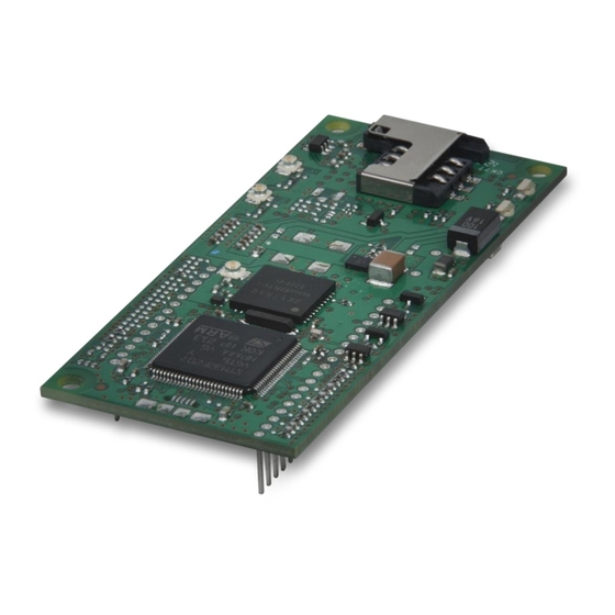
CHAPTER 1 – DEVICE OVERVIEW Chapter 1 – Device Overview Description The SocketModem Cell and iCell HSPA+ models are complete, ready-to-integrate communications devices that offer standards-based HSPA+ 21 performance. These quick-to-market communications devices allow developers to add wireless communication and GPS tracking to products with a minimum of development time and expense. Both models are based on industry-standard open interfaces and use Multi-Tech’s Universal Socket design. -
Page 6: Documentation
Documentation The following documentation is available by email to oemsales@multitech.com or by using the Developer Guide Request Form on the multitech.com Device Guide – This document. Provides model-specific specifications and developer information. Universal Socket Developer Guide – Provides an overview, safety and regulatory information, design considerations, schematics, and general device information. -
Page 7: Chapter 2 - Mechanical Drawing
CHAPTER 3 – SPECIFICATIONS Chapter 2 – Mechanical Drawing MTSMC-H5 All Builds SocketModem Cell HSPA and SocketModem iCell HSPA MTSMC-H5 Device Guide... -
Page 8: Chapter 3 - Specifications
CHAPTER 3 – SPECIFICATIONS Chapter 3 – Specifications Technical Specifications Category Description General Standards Penta-band HSPA+ 21 Quad-band GSM/GPRS/EDGE SMS is based on CS/Packet-Switched (PS) domain of GSM and WCDMA USB Interface is CDC-ACM compliant Frequency Bands Penta-band HSPA+: 850/900/1700/1900/2100 MHz Quad-band GSM/GPRS/EDGE: 850/900/1800/1900 MHz Speed Data Speed... -
Page 9: Mounting Hardware
CHAPTER 3 – SPECIFICATIONS Category Description Certifications, Compliance, Warranty EMC Compliance FCC Part 15 Class B FCC Part 15.31 (Co-location) EN55022 Class B EN55024 Radio Compliance FCC Part 22 FCC Part 24 RSS 132 RSS 133 EN 301 511 EN 301 489-1 EN 301 489-7 EN 301 489-24 Safety Compliance... -
Page 10: Device Reset
CHAPTER 3 – SPECIFICATIONS Device Reset The SocketModem is ready to accept commands after a fixed amount of time (“X” Time) after power-on or reset. Model Time Constant "X" Time Minimum Reset Pulse MTSMC-H5 250 ms 10 seconds 200 US The SocketModem may respond to a shorter reset pulse. -
Page 11: Pinout Specifications
CHAPTER 3 – SPECIFICATIONS Signal Name GPIO1 -0.3 GPIO2 -0.3 GPIO3 -0.3 -LED LINK 0.45 2.85 Pinout Specifications Signal Name Logic Level Voltage Description –RESET 3.3 – 5.0 Device reset (active low) USB VBUS 3.3 – 5.0 USB power supply input Ground USB DP USB data... -
Page 12: Pin 58
CHAPTER 3 – SPECIFICATIONS Pin 58 Note: Pin 58 may or may not be available on some SocketModems. Pin 58 LED Mode Operating Status Subscriber Carrier Mode is OFF or running in SLEEP or ALARM mode. 600 ms ON/600ms OFF No SIM card inserted, no PIN entered, network search in progress, ongoing user authentication, or network login in progress. -
Page 13: Power Measurements
CHAPTER 3 – SPECIFICATIONS Power Measurements Multi-Tech Systems, Inc. recommends that you incorporate a 10% buffer into your power source when determining product load. MTSMC-H5 Time (sec) to “ready Radio Protocol AT command used to Time (sec) to reduced Registered Power for data connection”... -
Page 14: Mtsmc-H5-U
CHAPTER 3 – SPECIFICATIONS Radio Instant Peak TX Peak Reset Current Peak Reset Current Protocol Current (Amps) (InRush) (Amps) (InRush) Duration 3.3 Volts GSM850 3.81A 1.82A 3.68ms HSDPA 700mA 1.82A 3.68ms 5 Volts GSM850 1.73A 1.95A 3.12ms HSDPA 390mA 1.95A 3.12ms Notes: ... -
Page 15: Mtsmc-H5-Ip
CHAPTER 3 – SPECIFICATIONS Radio Instant Peak TX Peak Reset Current Peak Reset Current Protocol Current (Amps) (InRush) (Amps) (InRush) Duration 3.3 Volts GSM850 3.53A 2.14A 4.80ms HSDPA 620mA 2.14A 4.80ms 5 Volts GSM850 1.48A 2.11A 3.00ms HSDPA 407mA 2.11A 3.00ms Notes: ... - Page 16 CHAPTER 3 – SPECIFICATIONS Radio Low Power Half Power Max Power Protocol Measured MS Xmit GSM Xmit Measured MS Xmit GSM Xmit Measured MS Xmit GSM Xmit Current or Power Power or Current Power or Current Power or (Amps) Cntrl HSDPA Ch (Amps) Power...
-
Page 17: Mtsmc-H5-Gp
CHAPTER 3 – SPECIFICATIONS MTSMC-H5-GP Radio Protocol AT command Radio Registration Data Radio Idle, SIM used to set installed and Peak Current Peak Current Time (sec) to radio function connected to tower Amplitude during Pulse Duration Peak and power mode (Amps) radio registration during radio... -
Page 18: Mtsmc-H5-Mi-Ip
CHAPTER 3 – SPECIFICATIONS Notes: AT+CFUN=1 used to set radio function and power mode. Instant Peak Tx: The peak current during a GSM850 transmission burst period or HSDPA connection. This current is handled by bulk capacitance in a design. ... -
Page 19: Mtsmc-H5-Mi-Gp
CHAPTER 3 – SPECIFICATIONS Radio Peak Amplitude Peak Current Peak Current Peak Current Peak Current Duration Protocol TX Current during power Duration during during Reset during Reset (InRush (Amps) for up (InRush powerup (InRush Amps) Duration) GSM850 or Peak Amps) (InRush Current for duration) - Page 20 CHAPTER 3 – SPECIFICATIONS Radio Low Power Half Power Max Power Protocol Measured MS Xmit GSM Xmit Measured MS Xmit GSM Xmit Measured MS Xmit GSM Xmit Current or Power Power or Current Power or Current Power or (Amps) Cntrl HSDPA Ch (Amps) Power...
-
Page 21: Additional Information For The Mtsmc-H5 Serial Device
CHAPTER 3 – SPECIFICATIONS Additional Information for the MTSMC-H5 Serial Device Mode Average (mA) Mode description IDLE mode (WCDMA) AT+CFUN=5 17ma Full Function with power save IDLE mode (GSM/EDGE) AT+CFUN=1 30ma Normal mode: full functionality of the module AT+CFUN=5 17ma Full function with power save. -
Page 22: Gsm Power Saving Modes For Serial Devices
CHAPTER 3 – SPECIFICATIONS Notes Issuing AT+CFUN=4[,0] actually causes the device to perform either a network deregistration or a SIM deactivation. Enabling power saving reduces power consumption during idle time, thus allowing a longer standby time with a given battery capacity. -
Page 23: Rts Control Of Power Mode At+Cfun=9
CHAPTER 3 – SPECIFICATIONS RTS Control of Power Mode AT+CFUN=9. Device in power saving mode, this command forces the module to monitor the RTS control line indicating if the user application (DTE) is ready to receive data from the module (DCE): ... -
Page 24: Chapter 4 - Device Specific Regulatory Information
CHAPTER 4 –DEVICE SPECIFIC REGULATORY INFORMATION Chapter 4 – Device Specific Regulatory Information The following is device specific FCC and Industry Canada information. For additional approval and regulatory information, see the Universal Socket Developer Guide. FCC Part 15 FCC Identifier RI7HE910 Equipment Class Part 15 Class Computing Device Peripheral... -
Page 25: Industry Canada
CHAPTER 4 –FCC AND INDUSTRY CANADA INFORMATION Industry Canada Certification Number/No. de Certification 5131A-HE910 Type of Radio Equipment/Genre de Matériel Advanced Wireless Services Equipment (1710-1755 MHz and 2110-2155 MHz) Cellular Mobile GSM (824-849 MHz) Modular Approval PCS Mobile (1850-1910 MHz) Model/Modele HE910 Specification/... - Page 26 CHAPTER 4 –DEVICE SPECIFIC REGULATORY INFORMATION The conformity assessment procedure referred to in Article 10 and detailed in Annex IV of Directive 1995/5/EC has been followed with the involvement of the following Notified Body: AT4 wireless, S.A. Parque Tecnologico de Andalucía C/ Severo Ochoa 2 295990 Campanillas –...
-
Page 27: Chapter 5 - Carrier Specific Information
CHAPTER 5 – CARRIER SPECIFIC INFORMATION Chapter 5 – Carrier Specific Information Notice for Devices that Use Aeris Radios One component of your device is a radio. A radio algorithm prevents your device from repeatedly attempting to connect to the network when the radio: ... -
Page 28: Chapter 6 - Application Notes
CHAPTER 6 –APPLICATION NOTES Chapter 6 – Application Notes LED Interface The LED signal indicates the SocketModem working status. Refer to the mechanical drawing for LED locations. LED 1 – Heartbeat – IP and –GP Builds Only LED 1 Signal Heartbeat LED No power to the unit. -
Page 29: Led 4 - Gps Status - Gp Builds
CHAPTER 6 –APPLICATION NOTES LED 4 – GPS Status – GP Builds LED 4 Signal GPS Status LED No power to the unit. Continuously lit Satellite not acquired. Blinking Satellite acquired. RF Performances RF performances are compliant with the ETSI recommendation 05.05 and 11.10. The module’s radio transceiver meets the requirements of 3GPP Release 5 &... -
Page 30: Frequency Bands
CHAPTER 6 –APPLICATION NOTES Frequency Bands Mode Freq. TX (MHz) Freq. RX (MHz) Channels TX - RX offset GSM850 824.2- 848.8 869.2 - 893.8 128 - 251 45 MHz EGSM900 890.0 - 914.8 935.0 - 959.8 0 - 124 45 MHz 880.2 - 889.8 925.2 - 934.8 975 - 1023...
Need help?
Do you have a question about the SocketModem Cell HSPA+ MTSMC-H5 Series and is the answer not in the manual?
Questions and answers