Table of Contents
Advertisement
Advertisement
Chapters
Table of Contents

Related Manuals for Gosafe G797


Summary of Contents for Gosafe G797
- Page 1 ...
-
Page 2: Table Of Contents
TABLE OF CONTENTS 1. Device Introduction 1.1 Physical Appearance 1.2 Speci cation 1.3 Features 2. Quick Install Instructions 2.1 Open device 2.2 Insert SIM card 2.3 Power on 2.4 Con guration 2.5 Location OBDII Port 2.4 Set User No. 2.5 Modify Password 2.6 Set Work Mode 3. -
Page 3: Device Introduction
G797 is easy to install device and even nonprofessionals can install this device. You only need to get the valid data SIM Card. Insert the SIM card in G797 and connect the device to OBDII port in the vehicle. The system have internal movement sensor which controls the power management of the device. -
Page 4: Physical Appearance
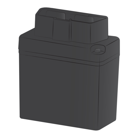
1.1 PHYSICAL APPEARANCE Device and Components Device opening to insert SIM card Front Cover Back Cover USB Port... -
Page 5: Front View
Accsessories RF Wireless Relay RF Tag USB Configuration cable Front View USB Port Wireless Module LED GPS/GSM LED... -
Page 6: Gps
1.2 SPECIFICATIONS Physical Specification Size 55 x 50 x 25 mm Weight 80 g IP Rating IP62 Power Rechargeable Battery Connector: J1962 Power Consumption 7.4V 180mAh Lithium ION Sleep Mode 500uA Active 70mA TI MSP430 12KB RAM, 256KB Flash Antenna Internal Modem uBlox LEON G100... -
Page 7: Features
Sensor 3D G-Force Sensor Onboard Memory Flash 10,000 Locations Environmental Conditions Operating Temperature -40°C to +70°C Storing Temperature -40°C to +85°C Humidity 1.3 FEATURES Real Time Location Mobile Map Location Latitude and Longitude Location GSM Base Station Location LBS Technology Convenient GSM Mobile Control Easy-to use SMS Communication Mode Internal Movement Sensor for better power management... -
Page 8: Quick Install Instructions
2.QUICK INSTALL INSTRUCTIONS 2.1 OPEN DEVICE Open G797 enclosure carefully by screwing off the four screws. - Page 9 2.2 INSERT SIM CARD Insert SIM card into the SIM card jacket correctly according to the below picture. Press SIM card inside the SIM card jack completely. Note Please do activate the SIM card, disable its PIN code function, and make sure SIM card has enough balance before operating the device.
-
Page 10: Power On
2.3 POWER ON Connect battery to the device, like the below picture shows you: 2.4 CONFIGURATION Connect USB cable to device and computer. Use the configuration software to configure. -
Page 11: Location Obdii Port
2.5 LOCATION OBDII PORT Normally ODBII port is available in all the vehicles manufactured after the 1996 and 2000. This port is located under the dash near the driving side of the vehicle. Normally this port is covered with some cover. -
Page 12: Set User No.
2.6 SET USER NO. with country code Message 1234,UNO;+8613912345678 without country code 1234,UNO;13912345678 Command Control Word Send SMS UNO:13912345678 Reply UNO:+8613912345678 Note After receipt of the above SMS command, device will reply a confirmation SMS and work at default work mode: 30M;G;W To protect device, if there is any error in this command, device will not send back any error warning. -
Page 13: Modify Password
2.7 MODIFY PASSWORD To modify factory password at the first usage is strongly suggested.. New Password Message 1234,UPW;5678 Command Control Word Factory Password Send SMS Reply UPW: 5678 Note Please memorize your New Password and wait for confirmation SMS for password modification from device. Only if this command is sent by user No., the system can process this command. -
Page 14: Set Work Mode
2.8 SET WORK MODE There are 4 different work modes configurable for device according to user’s need: O, S, G, and L. For detailed information on 4 work modes, please go to “Commands for Device Setting” in this User Manual. the type of message Message 1234,UUM;30M;G;T... -
Page 15: Command Table
3. COMMANDS FOR DEVICE SETTING All the commands for device setting in this User Manual are in the same format: 3.1 COMMAND TABLE The user command is shown in the below table. The whole command format is "PSW,CMDXX;Para". Table only show the second part "CMDXX;Para" in the column of command format. Description Ctrl Word Command... -
Page 16: Set Apn
Description Ctrl Word Command Reply Remarks Total is 20 bits"86" is national code, must have. Leave factory set: empty Default: usually, no Setting the 3. 1 .6 need to set SMS center number, SCN:+8613800200 when user use SIM card, device SCN;+8613800200500 center will record SMS center number... -
Page 17: Immobilizer Output
Description Ctrl Word Command Reply Remarks Set local time zone parameter from 12:00 to 12:00, Negative represent western time zone, Time zone 3. 1 . 1 2 TZN;8:00 TZN:8:00 positive represent east eastern setting time zone Default : 0 : 00 "0"... -
Page 18: Commands Wait
1 min, device would receive and process real time commands and will reply accordingly. 3.4 ALARMS The device sends alarm immediately when it triggers. The message received is as follows when device is in alarm. G797 V0.12 GPS 6/77 UTC 11 05 14 05:33:47 N23.164479 E113.428606... -
Page 19: Description
Description SMS Received Moving (When the vehicle I G797 V0.12 stopped and the movement GPS 6/77 sensor is enable, the device sends UTC 11 05 14 05:33:47 move alarm on the trigger N23.164479 of movement sensor) E113.428606 SPD:0km/h 0 Alarm: Moving Geo Fence (Future use the G797 V0.12... -
Page 20: Default Parameters
3.5 DEFAULT PARAMETERS Device is set with the following default parameters. When device powers up rst time it will use the following parameters to connect and wait for user commands or server commands. Description Parameter User number (EMPTY) SMS center number (EMPTY) PIN code of SIM 1234... -
Page 21: Normal Location Sms Format (G Mode)
4. STRUCTURES OF SMS FROM DEVICE 4.1NORMAL LOCATION SMS FORMAT (G MODE) (Located Successful) Gosafe G797 V0.10 Device Name and Version GPS 3/56 Satellites Connected &Time used for Location (secs) LTM08:00 11 24 10 02:54 Speci c time zone and Location time based on speci c time zone N23 9.8329... -
Page 22: Error Command Alert
(Located Unsuccessful Gosafe G797 V0.10 Device Name and Version MCC=460 Mobile Country Code MNC=1 Mobile Network Code LAC=517A Location Area Code CID=1FB1 Cell Identity TMP=25.6C Temperature PWR=12.5V Power 4.3 ERROR COMMAND ALERT Gosafe G797 V0.10 Error command! 4.4 PASSWORD MODIFICATION SUCCESSFUL CONFIRMATION Gosafe G797 V0.10... -
Page 23: Led Flashes & Relevant Device Status
5. LED FLASHES & RELEVANT DEVICE STATUS There is an external LED light to re ect device status in G797. In order to check device status through this LED light ashes, LED is located right next to the USB port. When device is at work, LED will ash at 8 sec cycle constantly to show related GSM and GPS status in each cycle. - Page 24 Error Details LED Flashes Solutions GSM module Communication 1 ash Power OFF then check GSM module power Error supply and communication SIM card Error 2 ashes Power OFF then check whether SIM installation is good and PIN is disabled Cannot register at GSM 3 ashes To check whether SIM card is overdue and/ network...
-
Page 25: Characters For Commands
6. APPENDIX 6.1 CHARACTERS FOR COMMANDS “ & ‘ < >... - Page 26 www.gosafesystem.com...
Need help?
Do you have a question about the G797 and is the answer not in the manual?
Questions and answers