Table of Contents
Advertisement
Advertisement
Table of Contents

Related Manuals for Gosafe G6S


Summary of Contents for Gosafe G6S
- Page 1 G6S/G3S User Manual V1.6 Copyright © 2013 Gosafe...
-
Page 2: Attention
⃞The device is susceptible to water and humidity. INSTRUCTIONS OF SAFETY ⃞This chapter contains information on how to operate “G6S/G3S” safely. ⃞BY following these requirements and recommendations you will avoid dangerous situations. You must read these instructions carefully and follow the strictly before operating the device! ⃞The device uses a 8V-32V DC power supply. -
Page 3: Legal Notice
Other products and company names mentioned herein may be trademarks or trade names of their respective owners. INTRODUCTION The G6S/G3S Feature Rich Powerful GPS Tracker is the latest solution for track and trace applications and extreme level fleet management. G6S/G3S is designed for service providers, integrators, and enterprise customers to enhance mobile resources and improve their dispatch system;... -
Page 4: Table Of Contents
G6S/G3S User Manual Contents ATTENTION! ................ 2 INSTRUCTIONS OF SAFETY ..........2 LEGAL NOTICE ..............3 INTRODUCTION ..............3 1. Packing List ..............5 2. Specifications ..............6 3. Overview ................. 7 4. Installation ..............9 5. I/O Connector ............... 11 6. -
Page 5: Packing List
G6S/G3S User Manual 1. Packing List ■Standard The G6S/G3S box is packaged with all the components that is necessary for operation, it contains: ⃞G6S/G3S device x1 ⃞2*8/2*5 PIN I/O connector cable x1 To connect with external To the back panel I/O... -
Page 6: Specifications
External antenna GPS Active Antenna Model uBlox NEO 6M Channel 50 Parallel Channels Accuracy Autonomous<2.5M Sensitivity -162dBm Vibration sensor Built-In Sensor Accelerate sensor Built-In, 2-axis Flash storage 16Mbits Built-In, Maximum to save 8,000 GPS postions NOTE: * indicates only for G6S... -
Page 7: Overview
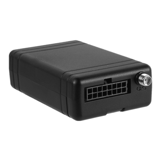
G6S/G3S User Manual 3. Overview 3.1. Device Capabilities FOTA, Firmware Upgrade Over The Air Flexible Programming Rules Garmin® FMI 1-Wire® Interface GSM Jamming Detection Quad Band GSM Modem HDOP For Precise Location Multiple Data Upload Modes ... - Page 8 G6S/G3S User Manual 3.2. Mechanical construction ■Front panel view This side towards to the sky LED indicator Battery power supply switcher USB cable port ■Rear panel view Cover remove slot GPS external antenna connector 2*8/2*5 PIN I/O connector...
-
Page 9: Installation
G6S/G3S User Manual 4. Installation 4.1. Remove the cover 1, On the back panel of the device, there is a small slot at the top of it. 2, Utilize a screw driver or sticker, insert it to the slot a little bit. - Page 10 G6S/G3S User Manual 4.3. Install direction ■G6S/G3S has accident & harsh detection features that based on built-in 2-axis sensor. Its accuracy will be affected by install direction of device, please find the sticker on housing of device for recommended direction.
-
Page 11: I/O Connector
OUT2 Digital output channel 2 Green AD1/IN3 Analog/Digital input channel High level active (>6V) Blue OUT1 Digital output channel 1 White ACC/Ignition signal input High level active Black Negative (-) Positive (+) 8V-32V DC NOTE: * indicates only for G6S... -
Page 12: Led Indicator Behavior
G6S/G3S User Manual 6. LED Indicator Behavior ■GSM LED: Green Server socket connected: Flash once quickly every 3 seconds GSM network registered: Flash twice quickly in a row every 3 seconds GSM network unregistered: Flash 3 times quickly in a row every 3 seconds... -
Page 13: User Command
G6S/G3S User Manual 7. User Command ■Set User Phone Number There are 2 users phone supported by G6S, they have the same authorization. User1’s command words are UNO0, UPW0, USP0. User2’s command words are UNO1, UPW1, USP1. Below will take user1 as example: To set your cell phone number as User1 to control and receive messages from device, please send UNO command to the device, e.g.:... - Page 14 G6S/G3S User Manual Explanations: 1234: User password USP0: Command control word 0: Interval Mode, related with dynamic report condition 0: Mode0 1: Mode1 30S: Report interval S: Second, range from 30 to 900. M: Minute, range from 15 to 59.
-
Page 15: Message Explanation
G6S/G3S User Manual 8. Message Explanation ■Periodical SMS report Below are the different kinds of message will be received by user periodically according to the setting of command USP, example on G6S. “W” mode 1. GPS is fixed Content of message Explanation G6S V1.00... - Page 16 G6S/G3S User Manual “T” mode 1. GPS is fixed Content of message Explanation G6S V1.00 Device name/Firmware version LTM 2013-06-06 09:41:22 Date/Time GPS 1.55/0.50/3/4 HDOP/ALTITUDE in meter/Fixed satellite number/Time of first fixed N23.164302 N means north/S means south E113.428456 E means east/W means west...
- Page 17 G6S/G3S User Manual 3. GPS is not fixed Map hyper link will be LBS (URL1) instead of GPS Content of message Explanation G6S V1.00 Device name/Firmware version LTM 2013-06-06 14:17:12 Date/Time http://maps.google.com/maps?q... Google map hyper link ETD:6/ACC ON Event ID/User defined event name/Data...
-
Page 18: Appendix
G6S/G3S User Manual Appendix Optional accessory ■USB cable To the computer that To the front panel runs configuration tool of device ■GPS external antenna Item Parameter Antenna Center Frequency 1575.42±1MHz Band Width CF±5MHz Polarization RHCP Gain 5dBic(Zenith) V.S.W.R <1.5 50Ω... - Page 19 G6S/G3S User Manual Expose this terminal To the rear panel of device, under the sky GPS antenna connector ■Microphone Item Parameter Length 3 meters Material Al-Si Output impedance 2.2Kohm Sensitivity -30db to 60db Frequency 50HZ to1600HZ Channel Stereo PIN15 Black wire: To PIN15...
- Page 20 G6S/G3S User Manual ■1-Wire PIN15 White wire: To PIN15 Driver ID application PIN5 Red wire: To PIN5 PIN15 1 & 3: To PIN15 PIN5 2: To PIN5 ■Panic button PIN8/10 Black/White wire: To PIN8/10 Press button to send PIN15 Black wire: To PIN15...
- Page 21 White: To PIN3 Yellow: To PIN1 ■Immobilizer Immobilizer is an electronic security device fitted to an automobile that prevents the engine from running, it can be control by digital output channel from G6S/G3S PIN9/11/13 85: To +12V/24V 86: To PIN9/11/13...
Need help?
Do you have a question about the G6S and is the answer not in the manual?
Questions and answers