Queclink GV300 User Manual
Gsm/gprs/gps tracker
Hide thumbs
Also See for GV300:
- Quick start manual (2 pages) ,
- User manual (29 pages) ,
- User manual (21 pages)

Related Manuals for Queclink GV300


Summary of Contents for Queclink GV300
-
Page 1: User Manual
GV300 User manual GV300 GSM/GPRS/GPS Tracker User Manual Application Notes: TRACGV300UM001 Revision: 1.09 sales@eddywireless.com... - Page 2 Document Control ID General Notes Queclink offers this information as a service to its customers, to support application and engineering efforts that use the products designed by Queclink. The information provided is based upon requirements specifically provided to Queclink by the customers. Queclink has not undertaken any independent search for additional relevant information, including any information that may be in the customer’s possession.
-
Page 3: Table Of Contents
2.1. Check Part List ......................8 2.2. Parts List ........................9 2.3. Interface Definition ....................10 2.4. GV300 User Cable Colour ..................11 Getting Started ........................12 3.1. Opening the Case ....................12 3.2. Closing the Case ...................... 12 3.3. -
Page 4: Table Index
TABLE 3. PART LIST ........................ 9 TABLE 4. DESCRIPTION OF 16 PIN CONNECTIONS ............10 TABLE 5. GV300 USER CABLE COLOUR DEFINITION ........... 11 TABLE 6. GPS ANTENNA SPECIFICATION ................ 15 TABLE 7. ELECTRICAL CHARACTERISTICS OF IGNITION DETECTION ....16 TABLE 8. -
Page 5: Figure Index
FIGURE 15. TYPICAL CONNECTION WITH LED ..............19 FIGURE 16. GV300 LED ON THE CASE .................. 19 FIGURE 17. TYPICAL CONNECTION WITH RS232 PORT ........... 21 FIGURE 18. GV300 CONNECTION WITH GARMIN GPS SET ..........21 TRACGV300UM001 - 5 -... -
Page 6: Revision History
GV300 User manual 0. Revision History Revision Date Author Description of change 1.00 2011-8-10 Owen Feng Initial 1.01 2011-8-19 Owen Feng First review Leo Lei Vivi Zhu 1.02 2011-09-09 Owen Feng Add picture of new case(V3) 1.03 2011-09-27 Owen Feng Add “Switch ON the Backup Battery”... -
Page 7: Introduction
Emergency, geo-fence boundary crossings, low backup battery or scheduled GPS position as well as many other useful functions. Users can also use GV300 to monitor the status of a vehicle and control the vehicle by its external relay output. System Integrators can easily setup their tracking systems based on the full-featured @Track protocol. -
Page 8: Product Overview
GV300 User manual 2. Product Overview 2.1. Check Part List Before starting, check all the following items have been included with your GV300. If anything is missing, please contact your supplier. Figure 1. Appearance of GV300 TRACGV300UM001 - 8 -... -
Page 9: Parts List
GV300 User manual 2.2. Parts List Table 3. Part List Name Picture GV300 Locator 80*49*26 mm User Cable Extend Cable (Optional) GPS Antenna (Optional) DATA_CABLE_M (Optional) TRACGV300UM001 - 9 -... -
Page 10: Interface Definition
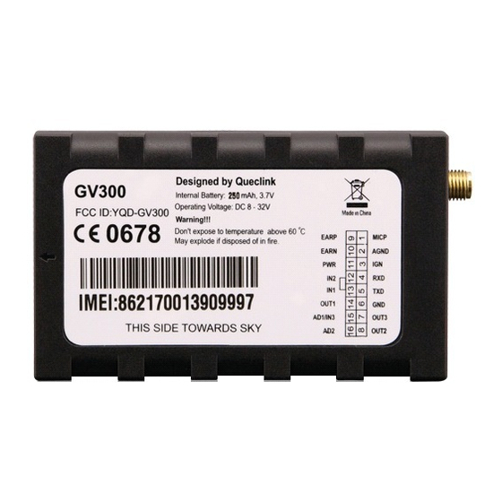
GV300 User manual 2.3. Interface Definition The GV300 has a 16 PIN interface connector. It contains the connections for power, I/O, RS232, microphone, speaker, etc. The sequence and definition of the 16PIN connector are shown in following figure: Figure 2. The 16 PIN connector on the GV300 Table 4. -
Page 11: Gv300 User Cable Colour
GV300 User manual 2.4. GV300 User Cable Colour Table 5. GV300 User Cable Colour definition Definition Definition Color Cable Color OUT2 Yellow Brown/White OUT3 Brown Green AD1/IN3 Black Blue OUT1 White/Black Orange Green or Pink Orange/Black White AGND Gray/ Black... -
Page 12: Getting Started
GV300 User manual 3. Getting Started 3.1. Opening the Case Figure 3. Opening the Case Insert the triangular-pry-opener into the gap of the case as shown below, push the opener up until the case unsnapped. 3.2. Closing the Case Figure 4. Closing the Case Place the cover on the bottom in the position as shown in the following figure. -
Page 13: Installing A Sim Card
GV300 User manual 3.3. Installing a SIM Card Open the case and ensure the unit is not powered (unplug the 16Pin cable and switch the internal battery to off position). Slide the holder right to open the SIM card. Insert the SIM card into the holder as shown below with the gold-colored contact area facing down taking care to align the cut mark. -
Page 14: Switch On The Backup Battery
GV300 User manual 3.5. Switch ON the Backup Battery To use the GV300 backup battery, the switch must be at the ON position. Switch on the case and ON/OFF position are shown below. Figure 7. Switch and ON/OFF position Note: 1. -
Page 15: Gps Antenna Specification
GV300 User manual 3.6.1. GPS Antenna Specification Table 6. GPS Antenna Specification GPS antenna: Frequency: 1575.42MHz Bandwidth: >5MHz Beam width: >120 deg Supply voltage: 2.7V-3.3V Polarization: RHCP Gain: Passive: 0dBi min Active: 15dB 50Ω Impedance: VSWR: <2 Noise figure: <3 3.7. -
Page 16: Ignition Detection
IGN signal can be configured to start transmitting information to backend server when ignition is on; and enter power saving mode when ignition is off. There are three general purpose digital inputs on GV300. They are all negative trigger. 3.9. Digital Inputs Table 8. -
Page 17: Analog Inputs
GV300 User manual Figure 11. Typical Digital Input Connection 3.10. Analog Inputs There are two analog inputs on GV300, the analog input voltage range is from 0 to 16V. The following diagram shows the recommended connection. Figure 12. Typical Analog Input Connection Note: PIN 15 is an multifunction pin: it can be configured as a digital input or an analog input. -
Page 18: Digital Outputs
GV300 User manual 3.11. Digital Outputs There are three digital outputs on GV300. All are of open drain type and the maximum drain current is 150 mA. Each output has the built-in over current and recovery PTC fuse Figure 13. -
Page 19: Device Status Led
If this diode is not internal, it should be added externally. A common diode such as a 1N4004 will work in most circumstances. 3.12. Device Status LED Figure 16. GV300 LED on the Case TRACGV300UM001 - 19 -... -
Page 20: Serial Port / Uart Interface
GV300 User manual Table 10. Definition of Device status and LED Device status LED status Device is searching GSM network Fast flashing (note1) (Note3) Device has registered to GSM network. Slow flashing (Note4) SIM card needs pin code to unlock. -
Page 21: Connect With Garmin Gps Set
GV300 User manual Figure 17. Typical Connection with RS232 Port 3.13.1. Connect With Garmin GPS Set GV300 can communicate with Garmin GPS Set. The following typical connection is using Queclink AG100 cable. Figure 18. GV300 connection with Garmin GPS set... -
Page 22: Gv300 Certification
4. GV300 certification 4.1. FCC certification GV300 has been tested and found to comply with the limits for a Class B digital device, pursuant to part 15 of the FCC Rules. This device complies with part 15B, part 22 and part 24 of the FCC rules. Operation is...
Need help?
Do you have a question about the GV300 and is the answer not in the manual?
Questions and answers