
Related Manuals for Queclink GV320


Summary of Contents for Queclink GV320
-
Page 1: User Manual
GV320 User manual GV320 GSM/GPRS/GPS Tracker User Manual TRACGV320UM001 Revision: 1.02 http://www.queclink.com TRACGV3SUM001 - 1 - sales@queclink.com... - Page 2 Document Control ID General Notes Queclink offers this information as a service to its customers, to support application and engineering efforts that use the products designed by Queclink. The information provided is based upon requirements specifically provided to Queclink by the customers. Queclink has not undertaken any independent search for additional relevant information, including any information that may be in the customer’s possession.
-
Page 3: Table Of Contents
2.1. Check Part List ........................... 8 2.2. Parts List ............................ 9 2.3. Interface Definition ........................9 2.4. GV320 User Cable Colour ....................... 11 3 Getting Started ..........................12 3.1. Opening the Case ........................12 3.2. Closing the Case ........................12 3.3. - Page 4 TABLE 3. PART LIST ........................9 TABLE 4. DESCRIPTION OF 16 PIN CONNECTIONS .............. 10 TABLE 5. GV320 USER CABLE COLOUR DEFINITION ............11 TABLE 6. GPS ANTENNA SPECIFICATION ................15 TABLE 7. ELECTRICAL CHARACTERISTICS OF IGNITION DETECTION ......15 TABLE 8.
- Page 5 GV320 User manual Figure Index FIGURE 1. APPEARANCE OF GV320 .................... 8 FIGURE 2. THE 16 PIN CONNECTOR ON THE GV320 .............. 10 FIGURE 3. OPENING THE CASE ....................12 FIGURE 4. CLOSING THE CASE ....................12 FIGURE 5. SIM CARD INSTALLATION ..................13 FIGURE 6.
- Page 6 GV320 User manual Revision History Revision Date Author Description of change 1.01 2012-05-07 Owen Feng Initial 1.02 2012-08-14 Leaf Ye Add uart Garmin connection TRACGV320UM001 - 6 -...
-
Page 7: Introduction
GPS position as well as many other useful functions. Users can also use GV320 to monitor the status of a vehicle and control the vehicle by its external relay output. System Integrators can easily setup their tracking systems based on the full-featured @Track protocol. -
Page 8: Product Overview
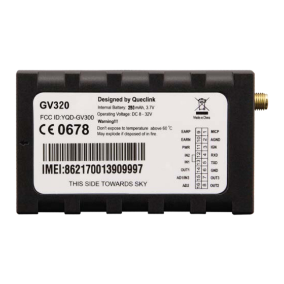
GV320 User manual 2 Product Overview 2.1. Check Part List Before starting, check all the following items have been included with your GV320. If anything is missing, please contact your supplier. Figure 1. Appearance of GV320 TRACGV320UM001 - 8 -... -
Page 9: Parts List
GPS Antenna (Optional) DATA_CABLE_M (Optional) 2.3. Interface Definition The GV320 has a 16 PIN interface connector. It contains the connections for power, I/O, RS232, microphone, speaker, etc. The sequence and definition of the 16PIN connector are shown in following figure:... -
Page 10: Table 4. Description Of 16 Pin Connections
GV320 User manual Figure 2. The 16 PIN connector on the GV320 Table 4. Description of 16 PIN Connections Index Description Comment MICP Single end, 2-2.2k microphone, internal bias AGND Analog ground Ignition input, positive trigger UART RXD, RS232 UART TXD, RS232... -
Page 11: Gv320 User Cable Colour
GV320 User manual 2.4. GV320 User Cable Colour Table 5. GV320 User Cable Colour definition Definition Definition Color Cable Color OUT2 Yellow Brown/White OUT3 Brown Green AD1/IN3 Black Blue OUT1 White/Black Orange Green Orange/Black White AGND Gray/ Black Purple/White EARN... -
Page 12: Getting Started
GV320 User manual 3 Getting Started 3.1. Opening the Case Figure 3. Opening the Case Insert the triangular-pry-opener into the gap of the case as shown below, push the opener up until the case unsnapped. 3.2. Closing the Case Figure 4. -
Page 13: Installing A Sim Card
GV320 User manual 3.3. Installing a SIM Card Open the case and ensure the unit is not powered (unplug the 16Pin cable and switch the internal battery to off position). Slide the holder right to open the SIM card. Insert the SIM card into the holder as shown below with the gold-colored contact area facing down taking care to align the cut mark. -
Page 14: Switch On The Backup Battery
GV320 User manual 3.5. Switch ON the Backup Battery To use the GV320 backup battery, the switch must be at the ON position. Switch on the case and ON/OFF position are shown below. Figure 7. Switch and ON/OFF position Note: 1-The switch must be on the “OFF”... -
Page 15: Gps Antenna Specification
GV320 User manual 3.6.1. GPS Antenna Specification Table 6. GPS Antenna Specification GPS antenna: Frequency: 1575.42MHz Bandwidth: >5MHz Beam width: >120 deg Supply voltage: 2.7V-3.3V Polarization: RHCP Gain: Passive: 0dBi min Active: 15dB Impedance: 50Ω VSWR: <2 Noise figure: <3 3.7. -
Page 16: Digital Inputs
IGN signal can be configured to start transmitting information to backend server when ignition is on; and enter power saving mode when ignition is off. 3.9. Digital Inputs There are three general purpose digital inputs on GV320. They are all negative trigger. Table 8. Electrical Characteristics of the digital inputs Logical State... -
Page 17: Analog Inputs
GV320 User manual Figure 11. Typical Digital Input Connection 3.10. Analog Inputs There are two analog inputs on GV320, the analog input voltage range is from 0 to 16V. The following diagram shows the recommended connection. Figure 12. Typical Analog Input Connection Note: PIN 15 is an multifunction pin: it can be configured as a digital input or an analog input. -
Page 18: Table 9. Electrical Characteristics Of Ddigital Outputs
GV320 User manual There are three digital outputs on GV320. All are of open drain type and the maximum drain current is 150 mA. Each output has the built-in over current and recovery PTC fuse Figure 13. Digital Output Internal Drive Circuit Table 9. -
Page 19: Device Status Led
2- All outputs are internally pulled up to PWR pin by a diode. So no external flyback diode is needed when the output is connected to an inductive load. 3.12. Device Status LED Figure 16. GV320 LED on the Case Table 10. Definition of Device status and LED TRACGV320UM001 - 19 -... -
Page 20: Serial Port / Uart Interface
GV320 User manual Note: Device status LED status Device is searching GSM network Fast flashing (note1) (Note3) Device has registered to GSM network. Slow flashing (Note4) SIM card needs pin code to unlock. GPS chip is powered off (note 2) GPS sends no data or data format error. -
Page 21: Figure 17. Typical Connection With Rs232 Port
Figure 17. Typical Connection with RS232 Port 3.13.1 Connect With Garmin GPS Set GV320 can communicate with Garmin GPS Set. The following typical connection is using Queclink AG100 cable. Figure 1. GV320 connection with Garmin GPS set Note: GV320 some version maybe connects with Garmin GPS set by Garmin FMI10/FMI15 cable, please consult with Queclink for detail information.
Need help?
Do you have a question about the GV320 and is the answer not in the manual?
Questions and answers