
Related Manuals for Queclink GV300TP


Summary of Contents for Queclink GV300TP
-
Page 1: Contents
GV300TP User manual GV300TP User Manual GSM/GPRS/GPS Tracker QSZTGV300TPUM001 Revision: R1.01 TRACGV3SUM001 - 1 -... - Page 2 QSZTGV300TPUM001 General Notes Queclink offers this information as a service to its customers, to support application and engineering efforts that use the products designed by Queclink. The information provided is based upon requirements specifically provided to Queclink by the customers. Queclink has not undertaken any independent search for additional relevant information, including any information that may be in the customer’s possession.
-
Page 3: Table Of Contents
2.1. Product Appearance ......................8 2.2. Parts List ..........................8 2.3. Interface Definition ......................9 2.4. GV300TP User Cable Color ....................11 3. Get Started ..........................12 3.1. Open the Case ........................12 3.2. Install a SIM Card ....................... 12 3.3. -
Page 4: Revision History
GV300TP User Manual 0.Revision History Revision Date Author Description of change 1.00 2017-08-10 Eddy Qi Initial 1.01 2019-08-18 Eddy Qi Add Bluetooth notes TRACGV300TPUM001 - 4 -... -
Page 5: Introduction
GPS position as well as many other useful functions. Users can also use GV300TP to monitor the status of a vehicle and control the vehicle by its external relay output. System integrators can easily set up their tracking systems based on the full-featured @Track protocol. -
Page 6: Product Overview
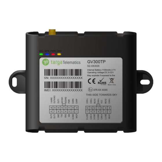
GV300TP User Manual Receive Data Transmit Data SPKN Speaker Negative SPKP Speaker Positive 2.Product Overview 2.1.Product Appearance Figure 1.Appearance of GV300TP 2.2.Parts List Table 4.Parts List Name Picture GV300TP Locator 122*85.2*24.2 mm Tracker Cable TRACGV300TPUM001 - 8 -... -
Page 7: Interface Definition
GV300TP User Manual 2.3.Interface Definition The GV300TP has two connectors which include a 16 PIN interface connector and a 14pin interface connector. The 16 Pin interface connector contains the connections for power, I/O, RS232, microphone, speaker, etc and the 14Pin interface connector contains High speed CAN, Low speed CAN, K-LINE, L-LINE . - Page 8 GV300TP User Manual AD2/IN2 Analog Input 2/ Negative Triggered 2 AD1/IN1 Analog Input 1/ Negative Triggered 1 OUT1 Negative Output 1 OUT4/IN3 Voltage output 4(12V) / Negative Output4/ Negative Triggered 3 1-Wire 1-wire Bus Table 6.Description of 14 PIN Connections...
-
Page 9: Gv300Tp User Cable Color
GV300TP User Manual 2.4.GV300TP User Cable Color Table 7.GV300TP User Cable Color Definition Definition Definition Color Cable Color OUT2 Yellow Brown/White 1-WIRE OUT3 Brown Green OUT4/IN3 Black Blue OUT1 White/Black Orange AD1/IN1 Pink Orange/Black AD2/IN2 White AGND Gray/Black Purple/White EARN... -
Page 10: Get Started
GV300TP User Manual 3.Get Started 3.1.Open the Case Figure 3.Open the Case 3.2.Install a SIM Card Open the case and ensure the unit is not powered (unplug the 16Pin cable and switch the internal battery to the OFF position). Slide the holder right to open the SIM card holder. Insert the SIM card into the slot as shown below with the yellow colour contact area facing down. -
Page 11: Install The Internal Backup Battery
Figure 5.Backup Battery Installation 3.4.Switch on the Backup Battery To use the GV300TP backup battery, the switch must be in the ON position. The switch on the case and the ON/OFF position are shown below. Figure 6.Switch and ON/OFF Position Note: 1. -
Page 12: Power Connection
GV300TP User Manual 3.5.Install the External GPS Antenna The GPS antenna is bought by the users themselves from a third party. GV300TP will automatically detect and use an external antenna when connected. We recommend the users to use an external antenna with following specifications:... -
Page 13: Ignition Detection
IGN signal can be configured to start transmitting information to the backend server when ignition is on, and enter the power saving mode when ignition is off. 3.8.Digital Inputs There are three general purpose digital inputs on GV300TP. They are all negative triggers. TRACGV300TPUM001 - 15 -... -
Page 14: Analog Inputs
The following diagram shows the recommended connection of a digital input. Figure 9.Typical Digital Input Connection 3.9.Analog Inputs There are two analog inputs on GV300TP, and the analog input voltage range is from 0 to 32V. The following diagram shows the recommended connection. Figure 10.Typical Analog Input Connection... -
Page 15: Digital Outputs
GV300TP User Manual 3.10.Digital Outputs There are four digital outputs on GV300TP for negative outputs (PIN7, PIN8, PIN14 and PIN15), also three of them(PIN7, PIN8 and PIN15) can be configurable as positive outputs. As negative outputs, all are open drain type and the maximum drain current is 150 mA; As positive outputs, OUT3 (PIN7) outputs 5V powered for One-wire bus, and two others (PIN8, PIN15) can output voltage 12V@200mA for 12V system or 24V@200mA for 24V system. -
Page 16: Device Status Led
If this diode is not internal, it should be added externally. A common diode such as a 1N4004 will work in most circumstances. 3.11.Device Status LED Figure 14.GV300TP LED on the Case TRACGV300TPUM001 - 18 -... - Page 17 GV300TP User Manual Table 11.Definition of Device Status and LED Device status LED status Device is searching GSM network. Fast flashing (Note 1) (Note 3) Device has registered to GSM network. Slow flashing (Note 4) SIM card needs pin code to unlock.
-
Page 18: Serial Port/Uart Interface
GV300TP User Manual 3.12.Serial Port/UART Interface There are two lines dedicated to the Serial Port/UART interface (TXD and RXD). TXD/RXD is standard RS232 signal. Figure 15.Typical Connection with RS232 Port 3.13.Reset Button Figure 16. Reset Button Use a thin pin to insert the hole and press the reset button if the device working in abnormal. - Page 19 GV300TP User Manual 4.FCC Statement This equipment complies with FCC radiation exposure limits set forth for an uncontrolled environment. This equipment should be installed and operated with minimum distance of 20 cm between the radiator and your body. This transmitter must not be co-located or operating in conjunction with any other antenna or transmitter.
Need help?
Do you have a question about the GV300TP and is the answer not in the manual?
Questions and answers