
Related Manuals for Queclink GV300CAN


Summary of Contents for Queclink GV300CAN
- Page 1 GV300 User manual GV300CAN User Manual GPS Tracker TRACGV300CANUM001 Revision: R1.02 TRACGV3SUM001 - 1 -...
- Page 2 TRACGV300CANUM001 General Notes Queclink offers this information as a service to its customers, to support application and engineering efforts that use the products designed by Queclink. The information provided is based upon requirements specifically provided to Queclink by the customers. Queclink has not undertaken any independent search for additional relevant information, including any information that may be in the customer’s possession.
-
Page 3: Table Of Contents
2.1. Check Parts List ......................8 2.2. Parts List ........................9 2.3. Interface Definition ....................9 2.4. GV300CAN User Cable Color ................... 10 Get Started ..........................11 3.1. Open the Case ......................11 3.2. Close the Case ......................11 3.3. - Page 4 TABLE 3. PARTS LIST ........................9 TABLE 4. DESCRIPTION OF 16 PIN CONNECTIONS ................ 10 TABLE 5. GV300CAN USER CABLE COLOR DEFINITION ..............10 TABLE 6. GPS ANTENNA SPECIFICATION ..................14 TABLE 7. ELECTRICAL CHARACTERISTICS OF IGNITION DETECTION ..........15 TABLE 8.
-
Page 5: Figure Index
GV300CAN User Manual Figure Index FIGURE 1. APPEARANCE OF GV300CAN ................... 8 FIGURE 2. THE 16 PIN CONNECTOR ON THE GV300CAN ..............9 FIGURE 3. OPEN THE CASE ......................11 FIGURE 4. CLOSE THE CASE ......................11 FIGURE 5. SIM CARD INSTALLATION ....................12 FIGURE 6. -
Page 6: Revision History
GV300CAN User Manual 0. Revision History Revision Date Author Description of change 1.00 2017-09-12 Super Zhao Initial 1.01 2017-12-19 Super Zhao Adjust the pictures and some description 1.02 2018-01-22 Pablo Dang Add the note for SYNC switch TRACGV300CANUM001 - 6 -... -
Page 7: Introduction
GV300 User Manual 1. Introduction The GV300CAN is a compact GPS tracker designed for a wide variety of vehicle tracking applications. It has multiple digital/analog I/O interfaces that can be used for monitoring or controlling external devices. At the same time, it has integrated CAN and J1708 which decodes information from vehicles digital buses (CANbus and J1708).It also includes a 1-wire interface... -
Page 8: Product Overview
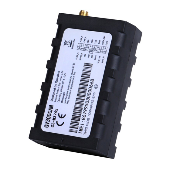
GV300CAN User Manual 2. Product Overview 2.1. Check Parts List Before starting, check whether all the following items have been included with your GV300CAN. If anything is missing, please contact your supplier. Figure 1. Appearance of GV300CAN TRACGV300CANUM001 - 8 -... -
Page 9: Parts List
GPS Antenna (Optional) MiniUSB_DATA_CABLE_1.5M (Optional) 2.3. Interface Definition The GV300CAN has a 16 PIN interface connector which contains the connections for power, I/O, RS232, CAN, J1708, 1-wire, etc. The sequence and definition of the 16PIN connector are shown in the following figure: Figure 2. -
Page 10: Gv300Can User Cable Color
Digital input, negative trigger OUT1 Open drain, 150 mA max ,with latch circuit VDD_1W 1-wire device power output ADC_IN ADC input 2.4. GV300CAN User Cable Color Table 5. GV300CAN User Cable Color Definition Definition Definition Color Cable Color OUT2 Yellow... -
Page 11: Get Started
GV300CAN User Manual 3. Get Started 3.1. Open the Case Figure 3. Open the Case Insert the triangular-pry-opener into the gap of the case as shown above, and push the opener up until the case is unsnapped. 3.2. Close the Case Place the cover on the bottom in the position as shown in the figure above. -
Page 12: Install A Sim Card
Take care to align the cut mark. Close the SIM card holder. Close the case. Figure 4. SIM Card Installation 3.4. Install the Internal Backup Battery GV300CAN has an internal backup Li-ion battery. Figure 5. Backup Battery Installation TRACGV300CANUM001 - 12 -... -
Page 13: Sync Switch
GV300CAN User Manual 3.5. SYNC Switch The switch was used to Synchronize the car model. You can push the switch to the left as the Arrow direction,and hold it approximately 3 seconds to Synchronize the car model。 Figure 6. SYNC Switch... -
Page 14: Install The External Gps Antenna (Optional)
GV300CAN User Manual 3.6. Install the External GPS Antenna (Optional) There is a SMA GPS antenna connector on GV300CAN. The GV300CAN will automatically detect and use an external antenna when connected. Figure 7. GPS Antenna of GV300CAN 3.6.1. GPS Antenna Specification Table 6. -
Page 15: Ignition Detection
GV300CAN User Manual Figure 8. Typical Power Connection 3.8. Ignition Detection Table 7. Electrical Characteristics of Ignition Detection Logical status Electrical characteristics Active 5.0V to 32V Inactive 0V to 3V or open Figure 9. Typical Ignition Detection TRACGV300CANUM001 - 15 -... -
Page 16: Digital Inputs
3.9. Digital Inputs There are two general purpose digital inputs on GV300CAN. They are all negative triggers. Table 8. Electrical Characteristics of the Digital Inputs Logical status... -
Page 17: Analog Inputs
Typical Analog Input Connection 3.11. Digital Outputs There are two digital outputs on GV300CAN. All are of open drain type and the maximum drain current is 150 mA. Each output has the built-in over current PTC resettable fuse. Figure 12. - Page 18 GV300CAN User Manual Figure 13. Typical Connection with Relay Figure 14. Typical Connection with LED Note: 1. OUT1 will latch the output state during reset. 2. Many modern relays come with a flyback diode pre-installed internal to the relay itself. If the relay has this diode, ensure the relay polarity is properly connected.
-
Page 19: Serial Port/Uart Interface
It has 1-wire bus on GV300CAN, which supports temperature sensors and iButton. The bus includes 3 signals, namely, VDD-1W, DATA-1W and GND. VDD-1W is the power output for 1-wire device, and DATA-1W is the data signal, with which GV300CAN can get information from 1-wire device. - Page 20 GV300CAN User Manual Figure 16. Typical Connection with 1-wire Device Figure 17. Typical Connection with iButton Reader TRACGV300CANUM001 - 20 -...
- Page 21 GV300CAN User Manual Figure 18. Typical Connection with Temperature Sensor TRACGV300CANUM001 - 21 -...
-
Page 22: Device Status Led
GV300CAN User Manual 3.14. Device Status LED Table 10. Definition of Device Status and LED Device status LED status Device is searching GSM network. Fast flashing (Note 1) (Note 3) Device has registered to GSM network. Slow flashing (Note 4) SIM card needs pin code to unlock. -
Page 23: Bluetooth
GV300CAN User Manual Figure 19. GV300CAN LED on the Case Note: 1. GSM LED cannot be configured. 2. GPS LED and PWR LED can be configured to turn off after a period of time by using the configuration tool. 3. Fast flashing: for GSM LED is about 60 ms ON/780 ms OFF; for GPS LED and PWR LED is about 100 ms ON/100 ms OFF. - Page 24 GV300CAN User Manual 3.15.1. Bluetooth usage Install Lightblue APP on your smartphone for IOS, and install NRF Connect for Android. Send command: “AT+GTBTS=gv300can,1,,GV300CAN_BT,7,3,666,1D07,0003,0,123456,,,,,,,,,,,,FFFF$” by Manage Tool to device to turn on Bluetooth. The device will connect to smartphone. Send command “AT+GTBTS=gv300can,0,,GV300CAN_BT,7,3,666,1D07,0003,0,123456,,,,,,,,,,,,FFFF$”...
Need help?
Do you have a question about the GV300CAN and is the answer not in the manual?
Questions and answers