Queclink GV300 User Manual
Gsm/gprs/gps tracker
Hide thumbs
Also See for GV300:
- User manual (22 pages) ,
- Quick start manual (2 pages) ,
- User manual (29 pages)

Related Manuals for Queclink GV300


Summary of Contents for Queclink GV300
- Page 1 GV300 User manual GV300 User Manual GSM/GPRS/GPS Tracker TRACGV300UM001 Revision: R1.01 TRACGV3SUM001 - 1 -...
- Page 2 TRACGV300UM001 General Notes Queclink offers this information as a service to its customers, to support application and engineering efforts that use the products designed by Queclink. The information provided is based upon requirements specifically provided to Queclink by the customers. Queclink has not undertaken any independent search for additional relevant information, including any information that may be in the customer’s possession.
-
Page 3: Table Of Contents
2.1. Check Parts List ......................8 2.2. Parts List ........................9 2.3. Interface Definition ....................10 2.4. GV300 User Cable Color ..................11 Get Started ..........................12 3.1. Open the Case ......................12 3.2. Close the Case ......................12 3.3. - Page 4 TABLE 3. PARTS LIST ......................... 9 TABLE 4. DESCRIPTION OF 16 PIN CONNECTIONS ..............10 TABLE 5. GV300 USER CABLE COLOR DEFINITION ..............11 TABLE 6. GPS ANTENNA SPECIFICATION ................15 TABLE 7. ELECTRICAL CHARACTERISTICS OF IGNITION DETECTION ........16 TABLE 8.
- Page 5 GV300 User Manual Figure Index FIGURE 1. APPEARANCE OF GV300 .................... 8 FIGURE 2. THE 16 PIN CONNECTOR ON THE GV300 ..............10 FIGURE 3. OPEN THE CASE ....................... 12 FIGURE 4. CLOSE THE CASE ...................... 12 FIGURE 5. SIM CARD INSTALLATION ..................13 FIGURE 6.
-
Page 6: Revision History
GV300 User Manual 0. Revision History Revision Date Author Description of change 1.00 2014-11-17 Super Zhao Initial 1.01 2015-04-01 Lizzy Li Updated the format of the document. TRACGV300UM001 - 6 -... -
Page 7: Introduction
GPS position as well as many other useful functions. Users can also use GV300 to monitor the status of a vehicle and control the vehicle by its external relay output. System integrators can easily set up their tracking systems based on the full-featured @Track protocol. -
Page 8: Product Overview
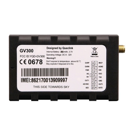
GV300 User Manual 2. Product Overview 2.1. Check Parts List Before starting, check whether all the following items have been included with your GV300. If anything is missing, please contact your supplier. Figure 1. Appearance of GV300 TRACGV300UM001 - 8 -... -
Page 9: Parts List
GV300 User Manual 2.2. Parts List Table 3. Parts List Name Picture GV300 Locator 80*49*26 mm User Cable GPS Antenna (Optional) DATA_CABLE_M (Optional) TRACGV300UM001 - 9 -... -
Page 10: Interface Definition
GV300 User Manual 2.3. Interface Definition The GV300 has a 16 PIN interface connector which contains the connections for power, I/O, RS232, microphone, speaker, etc. The sequence and definition of the 16PIN connector are shown in the following figure: Figure 2. The 16 PIN Connector on the GV300 Table 4. -
Page 11: Gv300 User Cable Color
GV300 User Manual 2.4. GV300 User Cable Color Table 5. GV300 User Cable Color Definition Definition Definition Color Cable Color OUT2 Yellow Brown/White OUT3 Brown Green AD1/IN3 Black Blue OUT1 White/Black Orange Pink Orange/Black White AGND Gray/Black Purple/White EARN MICP... -
Page 12: Get Started
GV300 User Manual 3. Get Started 3.1. Open the Case Figure 3. Open the Case Insert the triangular-pry-opener into the gap of the case as shown above, and push the opener up until the case is unsnapped. 3.2. Close the Case Figure 4. -
Page 13: Install A Sim Card
Take care to align the cut mark. Close the SIM card holder. Close the case. Figure 5. SIM Card Installation 3.4. Install the Internal Backup Battery GV300 has an internal backup Li-ion battery. Figure 6. Backup Battery Installation TRACGV300UM001 - 13 -... -
Page 14: Switch On The Backup Battery
GV300 User Manual 3.5. Switch on the Backup Battery To use the GV300 backup battery, the switch must be in the ON position. The switch on the case and the ON/OFF position are shown below. Figure 7. Switch and ON/OFF Position Note: 1. -
Page 15: Gps Antenna Specification
GV300 User Manual 3.6.1. GPS Antenna Specification Table 6. GPS Antenna Specification GPS antenna Specification Frequency 1575.42 MHz Bandwidth >5 MHz Beam width >120 deg Supply voltage 2.7V-3.3V Polarization RHCP Gain Passive: 0 dBi min Active: 15 dB Impedance 50Ω... -
Page 16: Ignition Detection
3.9. Digital Inputs There are three general purpose digital inputs on GV300. They are all negative triggers. Table 8. Electrical Characteristics of the Digital Inputs Logical status... -
Page 17: Analog Inputs
Figure 11. Typical Digital Input Connection 3.10. Analog Inputs There are two analog inputs on GV300, and the analog input voltage range is from 0 to 16V. The following diagram shows the recommended connection. Figure 12. Typical Analog Input Connection Note: PIN 15 is a multifunction pin: it can be configured as a digital input or an analog input. -
Page 18: Digital Outputs
GV300 User Manual 3.11. Digital Outputs There are three digital outputs on GV300. All are of open drain type and the maximum drain current is 150 mA. Each output has the built-in over current PTC resettable fuse. Figure 13. Digital Output Internal Drive Circuit Table 9. -
Page 19: Device Status Led
GV300 User Manual Device status LED status Figure 15. Typical Connection with LED Note: 1. OUT1 will latch the output state during reset. 2. Many modern relays come with a flyback diode pre-installed internal to the relay itself. If the relay has this diode, ensure the relay polarity is properly connected. - Page 20 Fast flashing External power in and internal battery is fully charged. Figure 16. GV300 LED on the Case Note: 1. GSM LED cannot be configured. 2. GPS LED and PWR LED can be configured to turn off after a period of time by using the configuration tool.
-
Page 21: Serial Port/Uart Interface
GV300 User Manual 3.13. Serial Port/UART Interface There are two lines dedicated to the Serial Port/UART interface (TXD and RXD). TXD/RXD is standard RS232 signal. Figure 17. Typical Connection with RS232 Port TRACGV300UM001 - 21 -...
Need help?
Do you have a question about the GV300 and is the answer not in the manual?
Questions and answers