Table of Contents
Advertisement
Quick Links
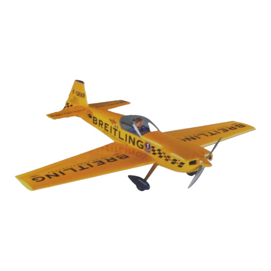
CAP 231EX ARF ASSEMBLY MANUAL
INTRODUCTION:
Congratulations on the purchase of your SIG CAP231EX ARF kit!
Properly assembled, powered and flown, this SIG ARF kit will
surely become one of your favorite models. Since the general con-
struction, sanding and covering have already been done at the fac-
tory, the only remaining tasks are those of assembly and radio and
engine installations.
Note that due to the large number of
useable engines for this model, we simply cannot cover every
possible installation. However, the volume provided inside the
large cowl should be helpful when mounting any engine within the
suggested size range.
The SIG CAP231EX ARF contains some of the lightest, best-
engineered construction of any ARF on the market. This is one of
the reasons it flies as well as it does, using the recommended
engine sizes. You will find that the CAP has superb take-off and
landing characteristics combined with remarkable aerobatic
capabilities.
The airframe has been specifically designed to
provide you with a "zeroed out" model. This is to say that the wings
and horizontal stabilizer sit at 0° in relationship to the
thrustline.
In turn, this provides you with a model that is
completely "honest" in any attitude. We will cover more set-up
information in the course of the following assembly instructions.
For those of you who are interested in 3-D work, we have
provided the CAP with double beveled rudder and elevator hinge
lines. This means that the flying surfaces can be driven to throws
in excess of 45° for 3-D maneuvers!
We urge you to follow these assembly instructions closely to
produce the model as it is intended to be. Modifications are the
very nature of modelers and we're sure that many of you will be
tempted. Simply be aware that certain assembly procedures for
this airplane must be followed. We will make a point of telling you
what these are as we proceed.
REQUIRED EQUIPMENT, TOOLS AND SUPPLIES
FOR ASSEMBLY:
RADIO EQUIPMENT
We highly recommend the use of one of the modern
programmable computer radios, such as the excellent Airtronics™
RD-6000 system, used during our development of this design.
Such radio systems allow you to easily set and adjust every
R
function and additionally pre-program various flight functions to
suit your individual style of flying. Four channels are required to fly
your CAP231EX; rudder, elevator, ailerons, and throttle.
However, you will require a total of six servos; ailerons-2,
elevators-2, rudder-1, and throttle-1.
Since your CAP 231EX is a large, highly aerobatic airplane and
because the control surfaces are also large, we urge you to use
appropriate servos on all flight surfaces (ailerons, elevator, and
rudder). This model should not be flown with "standard" 40 - 50
inch/ounce output servos! The CAP is big enough to impart very
large air loads and standard servos will quickly fail, resulting in loss
of control. You should use heavy-duty ball-bearing servos with at
least 65 inch/ounces of torque or more to drive the ailerons,
elevator, and rudder. If available, use a servo with metal gears
instead of plastic. Specifically in our prototype models, we used
Airtronics™ #94731 servos for the ailerons, elevators, and rudder.
This is a dual ball-bearing servo, rated at 80 inch/ounces of torque.
Another good choice is the Hitec™ #605MG servo (77
inch/ounces) or Hitec™ #615MG servo (107 inch/ounces). These
servos or equivalent from other manufacturers, can be relied upon
to work well thoughout the CAP's flight envelope.
A "standard" servo is adequate for the throttle.
We also suggest that you consider using after-market reinforced
plastic servo output arms, such as the Du-Bro "Super Strength"
products. These output arms are available to fit any servo. They
are very strong and work well with this model.
recommend their use with the pull-pull rudder system used in this
CAP. Using typical plastic servo output arms with the braided steel
cables for rudder control, may cause problems due to the
potential of wearing of the plastic by the cables over extended use.
The Du-Bro output arms are molded from considerably tougher
material and these have held up extremely well in our CAP
prototypes.
In addition to the servos, switch harness, receiver, etc., used in
normal airborne radio installations, you will also need two (2) 12"
aileron servo extensions, one (1) aileron Y-harness cable for the
two aileron servos, and a Y-harness splitter cable for the two
elevator servos. Note that the elevator Y-harness cable is used to
electronically connect both elevator servos to a single connector
going into the receiver. Normally, this requires reversing one of the
elevator servos, making it the "mirror image" of the opposite one,
mounted on the opposite fuselage side. However, we found a
great product that not only acts as an elevator Y-harness
cable/extension, it electronically reverses one of the elevator
servos and has a centering adjustment pot. This feature lets you
dial in the elevators exactly to a neutral relationship with each
other. This product is called the "Miracle Y™", sold by MAXX
PRODUCTS, Lake Zurich, Illinois. It can be ordered with any radio
manufacturer's connectors you specify.
tested this product and found it to be reliable, easy to use and very
reasonably priced. In addition, it is a total of 24" in length - 12" of
elevator extension cables and a 12" cable lead to the receiver.
Perfect for the CAP! Please refer to the Manufacturer's Index for
further contact information.
Finally, since you will be using a total of six servos to fly this
airplane, we strongly suggest you use a large capacity battery
pack for use in this model. We have used both 1000 Mah and 1200
Mah packs with very good results. Using the light 1000 Mah pack,
we have been able to safely fly five or six flights during any given
flying session, a reasonable amount of flying time for most
modelers. Naturally, a larger pack provides more flight time but
1
We highly
We have thoroughly
Advertisement
Table of Contents

Subscribe to Our Youtube Channel
Related Manuals for SIG CAP 231EX


Summary of Contents for SIG CAP 231EX
- Page 1 However, you will require a total of six servos; ailerons-2, elevators-2, rudder-1, and throttle-1. Since your CAP 231EX is a large, highly aerobatic airplane and because the control surfaces are also large, we urge you to use appropriate servos on all flight surfaces (ailerons, elevator, and rudder).
-
Page 2: Engine Selection
SIG employees. We urge you to be as careful as we have been, using the check-off blocks to inventory your kit before beginning The SIG CAP 231EX ARF has been flown with a variety of 2 and assembly. 4-stroke engines. As everyone knows, there is no substitute for... - Page 3 COVERING MATERIAL mounted on either the right or left side of the horizontal stabilizer. Your SIG CAP 231EX ARF kit has been expertly covered with #819 Dark Yellow Carl Goldberg Models ULTRACOTE®. Before leaving the factory, all covered parts were inspected and cleaned Begin by using a hobby knife to completely open up and clear each before being packed.
-
Page 4: Wing Assembly
1) Prepare the two wing panels for assembly by first using The flight surface can now be hinged in place. Begin by using a your hobby knife to remove the covering from the forward scrap wood stick to apply a coat of petroleum jelly, such as wing dowel mounting holes, the top round holes for the Vaseline®, to both sides of the hinge knuckle, as well as each end servo cable exits and the rear wing bolt mounting holes. - Page 5 Drill a 1/16" dia. hole near each corner of the hatch covers. hatch and apply thick CA or 5-minute epoxy the to bottoms Drill completely thru the hatch cover and into the hardwood of the servo blocks and glue them in place to the hatch, mounting beams that are in the wing.
- Page 6 exposed to engage the corresponding fuselage mounting holes. Use plenty of glue and a stick to get it into the two holes before inserting the dowels. Visually be sure these dowels are straight in the wings and not at angles. With the dowels in place, stand the wing up on its leading edge and allow the glue to cure.
-
Page 7: Engine Mounting
wing bolt holes already drilled in the rear center section of each wing panel. Use your hobby knife to remove the covering over the two wing bolt holes in the wing panels and the bolt plate. Place the plate in position over the trailing edge of the wing, aligning its rear edge with the fuselage bottom and its two bolt holes with the bolt holes in the wing panels. - Page 8 If you are using either the Irvine 1.20 or 1.50 2-stroke engines to power your CAP, SIG has a muffler available for these engines that is not only light in weight but fits perfectly within the cowl. This muffler is SIG part number IRV120150M and is available separately.
-
Page 9: Mounting The Cowl
7" deep. This size opening allows the exhaust pipes on thrust adjustments, if desired. Use scrap pieces of 1/16" the recommended SIG muffler for the Irvine engines to plywood to space the cowl behind the back surface of the clear the cowl with plenty of additional air exit area, as well spinner backplate. - Page 10 cowl, approximately 3-1/4" in from the outer edge. Stand the hole required for your engine's needle valve to exit the the triangle up against the bottom edge of the cowl, aligned cowl. This is easiest done using the penlight mentioned with the mark just made.
- Page 11 This spinner is a high quality locations just made. SIG unit that has been molded to accept APC propellers up to 16 x 8 in size. The shaft hole in the base of the spinner must be made to fit your particular engine.
- Page 12 3) As shown, assemble the nylon bearing bracket to the fuselage. Use a trim seal iron to tack the loose covering around into these cutouts. Trim and remove the excess longer of the two leaf springs with two 4-40 x 3/8" bolts and covering material.
- Page 13 one on either side of the tank. With these in place, a #64 plywood throttle tube support (small part with one rounded rubber band is hooked to one J-hook, pulled around the end with a hole for the tube), the pushrod connector tank and hooked to the opposite J-hook.
- Page 14 - this is the carburetor end. Install the brass pushrod centerline directly onto the stab at this location. Place the assembly to the output arm on the throttle servo and press stabilizer into the fuselage, centering it visually. Holding the the output arm in place onto the servo.
- Page 15 the fuselage and aligned with the centerline of the fuselage. Place one 1/2" length of heat shrink tubing onto one end of Wipe off any excess glue with alcohol. Adjust as needed the cable, followed by one of the 1/2" aluminum tubes. and tape securely.
- Page 16 the rudder horns to approximately the same mild tension - obtain "mirror image" elevator action. Install the splitter do not pull the cable tight. Remove the tape holding the cables through the back of the canopy hatch opening, back rudder in place, plug the rudder servo into your airborne to the two elevator servo cutouts.
- Page 17 stabilizer yet. location of this fairing onto the fuselage, stab and fin with a 21) Bolt the wing back in place to the fuselage. The horizontal pencil - remove the fairing. Use a sharp #11 blade to cut stabilizer is now glued in place. Use only slow-cure epoxy for this step.
- Page 18 the servo output arms in place at 90° upright. Attach the threaded ends of the axles and tighten these securely in solder clevis ends of the elevator pushrods to the servo place to the landing gear. Slide a wheel collar onto the axle output arms.
- Page 19 completed landing gear to the fuselage. drilled hole. From the outside, thread a nylon bolt in place through the hole and into the blind nut. Screw the bolt in place, bringing the ply pad firmly in contact with the fuselage side. Wipe off any excess glue.
- Page 20 any excess glue, while lightly pressing the canopy in place to the fuselage. Test the action of the aileron servos, adjusting the base. Secure the canopy to the base with pieces of masking tape linkages as needed to center them. Make sure the ailerons are and allow the glue to cure.
- Page 21 These numbers blade to cut and trim them at the hinge line. correspond to the CAP 231EX 3-view line drawing on the last page of this manual, providing you with their placement locations - Note: Applying the decals to the cowl is not difficult.
- Page 22 4" equals 27% of MAC (Mean Average Chord). have no real problems in test flying your CAP 231EX. Make reference, a balance point of 4-1/2" behind the wing's inboard L.E. yourself a simple checklist to assure your attention to the following equals 30% of MAC and 4-15/16"...
- Page 23 Assuming you're comfortable and getting used to the airplane, take it to a safe altitude and throttle back to get a feel for the slow flight We are sure that you will enjoy your CAP 231EX for a long time to and stall characteristics. Properly balanced and trimmed, your come.
-
Page 24: Manufacturer's Index
Tel: (847) 438-2233 AFTER MARKET Y-HARNESSES Fax: (847) 438-2898 INCIDENCE METER ROBART MFG., INC. P.O. Box 1247 St. Charles, IL 60174 CAP 231EX DOCUMENTATION SCALE MODEL RESEARCH FOTO-PAAK #5444 3114 Yukon Avenue Costa Mesa, CA 92626 Tel: (714) 979-8058 Fax: (714) 979-7279 IRVINE ENGINES SIG MANUFACTURING COMPANY, INC. -
Page 25: Academy Of Model Aeronautics
SIG MANUFACTURING CO. is totally committed to your success in both assembling and flying the CAP 231EX ARF kit. Should you encounter any problem building this kit, or discover any missing or damaged parts, please feel free to contact us by mail or telephone.
Need help?
Do you have a question about the CAP 231EX and is the answer not in the manual?
Questions and answers