Table of Contents
Advertisement
Quick Links
INTRODUCTION
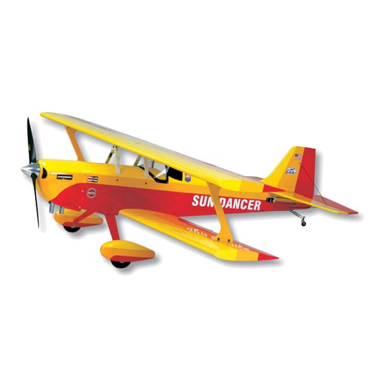
Congratulations on the purchase of the SIG Sun Dancer 50 ARF
kit! Properly assembled, powered, and flown, the Sun Dancer 50
will quickly become one of your favorite models. The construction
of this ARF kit has been extremely well engineered, providing an
airframe that is both light and strong. Of course, this translates
to outstanding flight characteristics when powered with the
recommend engine sizes.
take-off and landing characteristics, as well as remarkable
aerobatic capabilities. The airframe has been carefully designed to
provide you with a model that has a true "zeroed out" feel in the air.
This characteristic tends to provide a great deal of confidence
when performing those wild aerobatic maneuvers.
The engine choice for your Sun Dancer 50 is important. The
airplane will fly and fly well on good running .46 ball-bearing
engines. As your choice of engines increases in displacement and
power, obviously the airplane will respond accordingly. The largest
and most powerful engine we have flown in this model is the potent
YS .63 four-stroke. This engine, swinging an APC 12 X 6, provides
the Sun Dancer 50 with an outrageous amount of power, making
it definitely a "throttle management" type model.
recommend engines any larger or more powerful than the YS .63
for this model - it simply is not necessary.
We highly recommend that you follow the following assembly
instructions carefully. We also suggest that you take the time
to inventory the contents of your kit, using the included parts
information. Finally, the Sun Dancer 50 ARF is not recommended
for beginning R/C pilots. If this is your first R/C model, we urge you
to seek and use experienced help in both assembling and flying
this airplane.
Engine Note: Due to the large number of useable engines for this
model, we simply cannot cover every possible engine installation.
However, the large volume of space provided inside the cowling
should make it easy to mount virtually any engine within the
suggested size range.
RADIO EQUIPMENT:
We highly recommend the use of a modern computer radio for this
model. Such radio systems allow you to easily set-up and adjust
each channel and in addition, pre-program flight control functions
to suit your individual flying style. Four channels are required to fly
your Sun Dancer 50 - rudder, elevator, ailerons, and throttle.
The Sun Dancer 50 requires a total of five servos - ailerons (2),
elevator (1), rudder (1), and throttle (1).
inch/ounce servos will work well for this model. However, for
better precision, you can upgrade to ball bearing servos in the 60
The Sun Dancer 50 has excellent
We do not
Standard 40 to 50
to 80 inch/ in ounce range, such as Hitec HS-475HB, HS-545BB,
or HS-635BB or the Airtronics
For the rudder servo we have used and can recommend that you
consider using an after-market reinforced plastic servo arm such
as the Du-Bro "Super Strength" products. These output arms are
available to fit any brand of servo. They are quite strong and work
extremely well with this model. The Du-Bro output arms are
molded from considerably stronger material and have held up very
well in our prototypes.
You will also need three 6" servo extensions and one standard
Y-harness cord or 6" double link extension for the ailerons. In
addition, you'll also need one 12" servo extension for the aft
mounted elevator servo. These after-market items can usually be
obtained from either the manufacturer/distributor of your particular
radio system or from aftermarket suppliers, such as Maxx Products
in Lake Zurich, Illinois.
Last, because the Sun Dancer 50 uses a total of 5 servos, we
suggest that you consider the use a larger capacity airborne
battery pack. A battery pack in the 1000+mAh range will provide
ample time to safely fly at least five or six flights during any given
flying session. This is a reasonable amount of time for most
modelers. Naturally, a larger pack provides more flight time but
remember that larger can also equate too heavier.
suggest that you routinely use an Expanded Scale Voltmeter (ESV)
at the field to check the charge condition of your batteries. This
common piece of field equipment can save your model!
ENGINES & PROPELLERS:
The Sun Dancer 50 has been flown with a variety of engines, both
2 and 4-stroke. As everyone knows, there is no substitute for
power and the engine sizes recommended for this model all
provide good power margins.
2-stroke engines in the .46 to .53 sizes and 4-stroke engines in the
.56 to .72 displacements. Naturally, the larger engines in this range
make more power and will fly the Sun Dancer 50 with more
authority than the smaller engines. It is simply a matter of how you
want to fly the airplane. You also need to choose a propeller size
that is suitable for your particular engine, based on the
manufacturer's recommendations.
gaining experience, you can experiment with different propellers to
find the optimum combination for your engine and airplane.
The Sun Dancer 50 was designed from the start for glow engines
and provides ample room inside the cowling to comfortably fit most
of the popular engines that are available in both 2 and 4-stroke
types.
COVERING MATERIAL:
Your Sun Dancer 50 has been professionally covered with SIG
AEROKOTE
®
. If you live in a drier climate, you may notice that
some wrinkles might develop after removing the covered parts
from their plastic bags. If that is the case, there is no need to be
alarmed. The covering is not defective. This is normal and has and
nothing to do with the covering material or how it was applied.
Balsawood takes on or loses ambient humidity. Your Sun Dancer
50 was manufactured in a relatively humid region of the world. The
wood was therefore holding some humidity at the time the parts
were covered and bagged. When these parts are removed from
their bags and subjected to drier conditions, the wood quickly loses
moisture and the covering may appear loose. This also explains
why most iron-on coverings stay tight in the summer only to loosen
a little in drier winter conditions.
1
®
94731Z, 94738Z or 94743Z servos.
The practical range runs from
After flying the model and
We also
Advertisement
Table of Contents

Related Manuals for SIG SUN DANCER 50


Summary of Contents for SIG SUN DANCER 50
- Page 1 Properly assembled, powered, and flown, the Sun Dancer 50 will quickly become one of your favorite models. The construction Last, because the Sun Dancer 50 uses a total of 5 servos, we of this ARF kit has been extremely well engineered, providing an suggest that you consider the use a larger capacity airborne airframe that is both light and strong.
-
Page 2: Required Tools
Bag #2: Bottom Wing, fully assembled & covered with AeroKote ® For part number reference, your Sun Dancer 50 ARF was covered Holes for inter-plane struts (4) pre-drilled in hard points with SIG AeroKote ®... - Page 3 10 each M3 X 10mm PWA Bolts 2 each 3mm Lock Nuts Some modelers may want to dress up their Sun Dancer 50 by using trim tape to separate and accent the main colors. Use a Bag #17: 2 Molded Plastic Aileron Servo Hatch Mounts (1 left, 1 right)
- Page 4 Simply remove the hatch under the tank compartment for access Another detail that dresses up the looks of the Sun Dancer 50 to the interior of the tank compartment. is the windshield frame.
-
Page 5: Top Wing Assembly
Clean up any excess slot in the center that can be used to accurately place and center glue drops, runs, or smears on the covering with SIG CA the hinge equally into both the wing panel and the aileron. To do DEBONDER and a paper towel. - Page 6 provided hardware, mount the nylon inter-connect horns in place hatch. Now lay the servo on the cover with the mounting lugs on to each aileron. The ailerons are now permanently hinged in the wood blocks and mark through the center of the grommets place, using the same procedure used on the top wing.
-
Page 7: Engine Mounting
The following photos show how Hole we installed our YS engine in the Sun Dancer 50, but these instructions should be similar for other engines as well. 9) The YS-63S fits with the bolts centered in the slots of the Flush motor mounts. -
Page 8: Fuel Tank Assembly
the inside of the fuselage, about 2" ahead of the throttle servo, 16) Insert the clunk fuel pick-up weight into one end of the using epoxy or thick CA. Trim the throttle housing tube so that it silicone fuel line that was inside of the tank. Lower this assembly only extends about 1/4"... - Page 9 inverted mounted engines you will need to open up the bottom of the cowl as shown in the picture to provide cylinder clearance and COWL AND MUFFLER CUTOUT TEMPLATE cooling air for the engine. Use the provided template above to mark out the area to be removed.
- Page 10 20) Most engines will require another cut out in the cowl to clear Cut a new length of 1/16" music wire about 4" long. Reinstall the cowl and insert the wire through the cowl and into the hole in the the exhaust system.
- Page 11 On the servo end of the cable, slide one of the copper swage tubes fuselage through the servo opening. Mount the elevator servo in onto the end of one of the cables. Then insert the end of the cable the fuselage at this time using the hardware and screws provided through the small hole in the end of a threaded rigging coupler, by the servo manufacturer.
- Page 12 gear and the gear to the fuselage in this configuration. Locate the Carefully mark this position on the bottom and top of the stabilizer, two fiberglass wheel pants and use the four M3 x 10mm bolts and then trim the covering to within 1/32" of your pencil marks to allow four 3mm lock washers to attach the wheel pants to the landing maximum surface for gluing.
-
Page 13: Tailwheel Assembly
Mount the two opposing nylon rudder control horns with two M2 x 15mm bolts and nuts. Locate the "T" bracket in the tail wheel assembly bag and mount it in place to the bottom of the rudder Use Drill with two M2 x 10mm screws. Now insert the two remaining rudder Template hinges into the leading edge of the rudder and hinge the rudder permanently in place using the same methods described in the... -
Page 14: Elevator Pushrod
ASSEMBLING THE PULL-PULL CABLES: swaging tube towards the rigging coupler. Use pliers or a crimping tool to squeeze the copper tube tightly over the cable to lock it in Note: It is important that the distance between the pull-pull cable place. -
Page 15: Radio Installation
Sun Dancer 50 prototypes, we located the battery pack directly beneath the fuel tank. First wrap the battery pack in foam rubber and cover it with a small plastic bag before inserting it under the fuel tank. Use a little extra foam rubber as needed to keep the pack from shifting. -
Page 16: Final Assembly
M3 x 10mm PWA bolts and 3mm lock nuts. Do not install the interplane struts at this time. 43) Because the Sun Dancer 50 is a biplane configuration, the incidence of the wings is twice as critical and therefore must be MODELER’S TIP: To give your model that professional look,... -
Page 17: Control Movements
Carefully cut out the decal and lift it off now installed to drive the upper ailerons from the lower ailerons. of the sheet with tweezers. Use a product like SIG Pure Magic Use tape to hold the two upper ailerons in the neutral position. -
Page 18: Center Of Gravity
"pitch" (up and down). We have opposite side. Properly trimmed, the SUN DANCER 50 will roll flown the SUN DANCER 50 with the C.G. as far back as 3-5/8" and smoothly and very axially in either direction. Now try a loop. The found it to be manageable, with excellent aerobatic capabilities. - Page 19 Landing the SUN DANCER 50 is a pleasure. We like to keep a We hope you will enjoy your SUN DANCER 50 for a long time to little power on the engine during final approach, down to a few feet come.
- Page 20 SUN DANCER 50 ARF LOG BOOK Date of first flight: Comments:...
-
Page 21: Academy Of Model Aeronautics
SIG MANUFACTURING COMPANY, INC. is committed to your success in both assembling and flying the SUN DANCER 50 ARF kit. Should you encounter any problem building this kit, or discover any missing or damaged parts, please feel free to contact us by mail or telephone. - Page 22 Having the right fuel for your glow engine is as simple as making With over thirty-five different blends, you’ll find the formula sure the SIG label is on your bottle. Each gallon of SIG fuel is right for your engine and your flying style. Each gallon is clearly...
Need help?
Do you have a question about the SUN DANCER 50 and is the answer not in the manual?
Questions and answers