Table of Contents
Advertisement
Sig Mfg. Co., Inc...401-7 S Front St ...PO Box 520....Montezuma IA 50171-0520
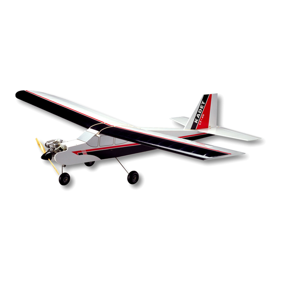
Welcome to the sport of Radio Control flying, and thank you for choosing the SIG KADET LT-40.
We understand how anxious you are to get started building and flying your KADET LT-40, but please take a few minutes right
now to study the full-size plans while you page through these instructions. This will familiarize you with the general layout of the
airplane and the building sequence, making the entire project easier in the long run.
Introduction
In order for your KADET LT-40 to fly as well as it was designed to, it must be carefully assembled. A model airplane that is not
built properly will not fly properly! Remember to work slowly and follow the instructions exactly. SIG, as the kit manufacturer, can
provide you with a proven aerodynamic design, quality materials, and detailed instructions, but ultimately the flyability of your
finished model depends on how well YOU put it all together.
Customer Service
SIG Mfg. Co., Inc. is totally committed to your success in building and flying the KADET LT-40. Should you encounter any
problem building this kit, or find any missing or damaged parts, feel free to contact us by mail or phone.
SIG MFG. CO., INC.
401-7 S Front St
P.O. Box 520
Montezuma, IA 50171-0520
SIG MODELER'S HOTLINE: 1-641-623-0215 Weekdays, 7:00am - 4:30pm Central
Advertisement
Table of Contents

Subscribe to Our Youtube Channel
Related Manuals for SIG KADET LT-40


Summary of Contents for SIG KADET LT-40
-
Page 1: Customer Service
Introduction In order for your KADET LT-40 to fly as well as it was designed to, it must be carefully assembled. A model airplane that is not built properly will not fly properly! Remember to work slowly and follow the instructions exactly. SIG, as the kit manufacturer, can provide you with a proven aerodynamic design, quality materials, and detailed instructions, but ultimately the flyability of your finished model depends on how well YOU put it all together. - Page 2 The craftsmanship, attention to detail, and actions of the builder/flyer of this model airplane kit will ultimately determine the flight performance and safety of the finished model. SIG MFG. CO.’s only obligation shall be to replace those parts of the kit proven to be defective or missing.
- Page 3 Wood parts such as standard stick and sheet stock, leading edges, trailing edges, ailerons, elevator, etc., are all easily identifiable by comparing their shape and dimensions to the plans and the KADET LT-40 COMPLETE PARTS LIST; therefore we did not feel that there was any need to label these parts. On the other hand, proper identification of the different wing ribs, wing sheeting, fuselage formers, etc., can be confusing because some of them are very similar looking, but in fact they are quite...
- Page 4 NOTE: The edges of all the laser-cut parts have a "burnt" appearance varying from light brown to dark black, depending upon the thickness and type of material the part is made of. Our tests indicate that a slight discoloration of the edges does not significantly affect the bonding ability of these parts.
- Page 5 Additional Components Needed The following items are not supplied in this kit but are needed to complete the KADET LT-40. Because of the wide variety of brands available and the influence of personal preferences, the choice of these items is left to the builder to select.
- Page 6 However, if you want to get your KADET LT-40 into the air as quickly as possible, we recommend that you use CA glue for the majority of the assembly of this kit.
- Page 7 For holding parts together during construction. - Masking Tape or Scotch Tape For holding parts together during construction. - #32 or #64 Rubber Bands (such as SIG #SH-364 or SIG #SH-366) Used to hold the fuselage parts together during initial assembly. - Scissors...
- Page 8 Panels, Stabilizer, and Fin - which will be assembled directly on top of the plans. The plans also show how we would install a typical radio and engine in the KADET LT-40. By referring to the examples shown on the plan, you should be able to properly install your radio and engine, even if they are not exactly the same as what is shown on the plan.
- Page 9 WING PANEL CONSTRUCTION The KADET LT-40’s wing is designed to be built in two halves - called the LEFT WING PANEL and the RIGHT WING PANEL (see full-size Plan Sheet 2). Each wing panel should be built directly on top of its own plan, using the plan as a pattern to position the parts.
- Page 10 8. Pin the pre-shaped balsa Trailing Edge in place on the plan, gluing it to the back edge of WS-B3 at the same time. Be sure to align all of the notches in the Trailing Edge with the wing rib locations on the plan. NOTE: It is possible for plan paper to shrink or expand slightly with humidity changes.
- Page 11 18. Glue the pre-shaped balsa Leading Edge in place in the notches in the front of the wing ribs. CAUTION: Take a close look at the end of the Leading Edge before gluing it in place! Notice that it is not symmetrical! Hold the Leading Edge against one of the wing cross-section drawings on Plan Sheet 2, and after you are sure that you have it matched up correctly, mark an "up"...
- Page 12 24. Once in position, securely glue WTP to all the other parts it comes in contact with. NOTE: Practically everywhere that WTP comes in contact with another part there are angles involved. This means there will naturally be some unavoidable small gaps between the parts.
-
Page 13: Joining The Wing Panels
JOINING THE WING PANELS 30. The first thing you need to do is check the fit of the two wing panels to each other - WITHOUT GLUE! Start by locating die-cut lite-ply part DTG (dihedral tip gauge) and pinning it to the underside of the last W5 rib (nearest the wing tip) in the Left Wing Panel. -
Page 14: Aileron Installation
34. Carefully slide both MADBs into position in the Right Wing Panel. Push them in slowly, being careful not to snag and break the W1 or W2 ribs. Position both MADBs carefully before gluing them to the spars. Check: 1. that the MADBs are tight against the front and back of the Top & Bottom Main Spars; 2. - Page 15 NOTE: The threaded portion of the Torque Rods should lean back slightly towards the rear of the airplane when the ailerons are in neutral position. That rearward lean provides the KADET LT-40 with a small amount of "differential" movement in the ailerons (more up than down), which makes for smoother turning.
- Page 16 Torque Rod wire. The groove should go from the 3/32" hole you drilled in the last step to the root end of the aileron. Trial fit (without glue) the aileron over the end of the Torque Rod wire to check the fit. 55. Mark the locations for the Sig Easy Hinges (4 per aileron) on the leading edge of the ailerons and on the trailing edge of the wing.
- Page 17 62. Remove the ailerons and hinges from the wing and set them aside until "COVERING THE KADET LT-40" . COMPLETING THE WING 63. Use a sanding block with fresh 80 grit sandpaper to give the entire wing a final sanding. Sand just enough to take off...
- Page 18 WARNING: SIG EASY HINGES are designed to be used in conjunction with Thin CA glue. Thin CA (any brand) is the ONLY type of glue that can be used on EASY HINGES - do not use epoxy or any other type of...
- Page 19 Now make 3 or 4 more cuts in the exact same line, going slightly deeper each time. As you make these additional cuts, concentrate on staying in the slit and keeping the blade headed straight into the center of the wood so that it won’t come out the side of the part.
-
Page 20: Fuselage Construction
FUSELAGE CONSTRUCTION 74. Use a sanding block to very lightly sand the edges of all the die-cut plywood fuselage parts to remove any burrs or rough spots. Hold the sanding block at a 90 angle to the part while doing this. Remember, sand very lightly! You only want to smooth the edges of the parts, not change their size or shape. - Page 21 88. Glue a die-cut plywood FD (fuselage doubler) in place on top of each Fuse Side (FS-F/FS-R assembly). Use a slow drying glue, such as Sig Epoxy Glue or Sig-Bond aliphatic resin glue, for this step to allow you plenty of time to accurately position...
- Page 22 NOTES: Study the full-size plan to make sure you know exactly where FD should go before you apply the glue. Notice that there are some places where the edges of FD should be flush with the edges of the Fuselage Side (like the wing, hatch, and nose areas, etc.), and that there are other places where FD is inset 1/8"...
- Page 23 94. Slide die-cut plywood part FT-R (fuselage top rear) underneath the rubber bands at formers F3, F4, F5, and F6, and work it towards the tail, into final position between the fuselage sides. Lock the tabs on the sides of FT- R into the corresponding notches in the fuselage sides.
- Page 24 104. Double check to see that the rear of the fuselage structure, the area from former F3 all the way back to the tail end, is in correct alignment. Make sure that the structure is square and that all the parts are tightly held together without any significant gaps between parts.
-
Page 25: Stabilizer And Elevator
118. Use a razor saw to cut off the excess rudder pushrod tube as close as you can to the top of the fuselage. Then block sand the tube, and any excess glue, flush with the top. The basic fuselage construction is now complete! Set the fuselage aside until "COVERING THE KADET LT-40" STABILIZER AND ELEVATOR 119. - Page 26 Leading Edges to a round shape. NOTE: Leave the End Ribs and Trailing Edge of the Stabilizer flat and square. 130. Lay the Stabilizer back on the plan and mark the locations for the Sig Easy Hinges (4 total) on the trailing edge.
- Page 27 Sand the end of the Rudder slightly if necessary to achieve an adequate gap. 145. Cut slots for the hinges in the Fin and Rudder following the instructions on page 23 "INSTALLING SIG EASY HINGES" (perform steps 1 through 5). Then set the Fin and Rudder aside for covering.
-
Page 28: General Notes
The choice of which type of covering material to use on your KADET LT-40 is a matter of personal choice. - Page 29 Covering Cutting Diagram The diagrams below suggest how to cut 3 standard size rolls (26" x 6 ft.) of iron-on covering material for the KADET LT-40. We recommend that you take the time to layout each roll on a large, clean surface and cut it to the sizes shown in the diagram.
- Page 30 Cover The Rudder First cover both ends of the Rudder with small pieces of scrap covering material before covering the sides. Run the end covering "around the corner" about 1/8" onto the sides and front of the Rudder. Trim off excess. NOTE: Always be careful when trimming excess covering material off of wood parts that you don’t "score"...
- Page 31 Cover the right side of the Rudder in the same manner you did the left side, making sure that it overlaps all other pieces of covering material at least 1/8" and that no areas of wood are left exposed. NOTE: When applying covering to a large solid surface, like the sides of the Rudder, it’s best to start ironing in the center and work towards the outer edges, to avoid trapping air bubbles.
- Page 32 Finally, cover the sides of the fuselage with separate right and left pieces of covering material. These are the largest pieces of covering material you’ve worked with so far. Don’t hurry! You can’t cover a fuselage side in 10 minutes like you did the smaller parts.
- Page 33 Trim as close to the image as possible. Next spray the surface of the model where the decal will be placed with water mixed with a small amount of dish soap (you can also use "Sig Pure Magic Model Airplane Cleaner", "Fantastic", "Windex", or "409"...
-
Page 34: Final Assembly
If any glue remains between the front of the torque rod and the wing trailing edge, slide a piece of paper through there to mop up the excess. Let dry! 151. Return to the instructions on "INSTALLING SIG EASY HINGES", and perform steps 6 through 8 to glue the hinges permanently in place. - Page 35 155. Lift the rear of the fuselage up, without jarring the stab loose, enough to enable you to mark the location of both fuselage sides on the bottom of the stab with a pencil. 156. Remove the Stabilizer from the fuselage and very carefully strip away the covering material on the bottom, between the two lines, where the stab will be glued to the fuselage.
- Page 36 162. Find the plastic bag containing: six 5/32" Wheel Collars, six Set Screws, and one Hex Wrench. Thread a Set Screw halfway into each Wheel Collar. 163. Install one 3" dia. Main Wheel and two 5/32" Wheel Collars on the axle of each Main Gear Wire as shown: a Wheel Collar first, then the Wheel, then the other Wheel Collar.
-
Page 37: Radio Installation
.40 size R/C 2-stroke engine. 174. A 2" dia. SIG Spinner is included in this kit, packed in a plastic bag. Inside the bag you will also find two 4-40 socket-head bolts and a group of four molded plastic "adapter rings". - Page 38 Mounting The Fuselage Servos 178. Locate the die-cut plywood part FSM (fuselage servo mount). Mount your throttle, elevator, and rudder servos in FSM using the screws, washers, and rubber grommets that came with your radio system. Be sure to orient the servos in FSM as shown in the Fuselage Top View.
- Page 39 > Throttle Control 186. Assemble one Pushrod Connector in the middle hole of the throttle servo control arm. Assemble another Pushrod Connector in the bottom hole of the engine’s carburetor control arm. 187. Locate one piece of Straight Music Wire 1/16" dia. x18" long to make the throttle pushrod.
- Page 40 NOTE: Adjusting carburetor linkage can be a little tricky! If you have binding, check for an incorrect amount of offset (bend) in the pushrod wire at the carburetor. If necessary, re-bend the wire to eliminate the bind. If the throttle servo is binding or "stalling"...
- Page 41 197. Set the rudder in neutral position. Mark the servo end of the smaller (inner) nylon pushrod tube exactly 1" from the hole in the rudder servo arm. Cut off the nylon tube at the mark. 198. (Recall steps 193, 194, 195.) Cut another 10" Threaded Steel Rod to 7" overall length. Slide the plain end of the rod inside the servo end of the inner nylon pushrod tube, and screw a minimum of 1/8"...
- Page 42 That’s why you don’t see any Pushrod Connectors on the ailerons, elevator, or rudder pushrods of the KADET LT-40! If you have never soldered before, don’t worry, it’s not difficult. The hardest part will probably be coming up with a soldering iron (or gun).
- Page 43 Receiver Battery Pack 212. Wrap the battery pack with a single layer of 1/2" thick soft foam rubber to insulate it from engine vibration and shock. Use tape or rubber bands to hold the foam around the battery. Install the wrapped battery pack inside the nose of the model, under the fuel tank floor, in the position shown on the plan (fuselage side view).
-
Page 44: Fuel Tank
Fuel Tank 219. Pull the stopper cap out of the front of the fuel tank. Inside the tank there should be two brass tubes, one brass clunk weight, and a short piece of fuel line tubing. Shake the tank to get these parts out through the hole. You may have to reach inside the tank with a tweezers or needle nose pliers to get a hold of the fuel line tubing and pull it out (CAUTION: Don’t squeeze too hard and put a hole in the tubing). -
Page 45: Filling The Fuel Tank
BALANCE YOUR AIRPLANE We know that your KADET LT-40 looks done and you’re real anxious to go out and fly it, BUT WAIT A MINUTE - IT’S NOT REALLY DONE YET! It must be balanced! All airplanes, model or full-size, must be accurately balanced in order to fly successfully. - Page 46 235. Place a fingertip on each pencil mark and lift the airplane up in the air. No part of the model should be touching anything except your fingertips! If the KADET LT-40 will sit on your fingertips in a level or very slightly nose down attitude, then it is properly balanced and ready to fly.
-
Page 47: Find A Safe Place To Fly
Find A Safe Place To Fly Don’t try to fly your KADET LT-40 in your backyard, at the local school yard, or in any other heavily populated area! If you have never seen an R/C airplane fly before, you probably don’t realize how much room you really need. It’s more than most people think! A school yard may look inviting, but it is too close to people, houses, power lines, and possible radio interference. - Page 48 It’s not that learning to fly R/C is difficult, it’s just a lot different than anything you have ever done before. Anyone can learn to fly the KADET LT-40 if they are willing to listen and learn! Remember the first time you tried to ride a bicycle? It seemed completely awkward the first time, but once you learned how, it quickly became very easy.
Need help?
Do you have a question about the KADET LT-40 and is the answer not in the manual?
Questions and answers