Table of Contents
Advertisement
Quick Links
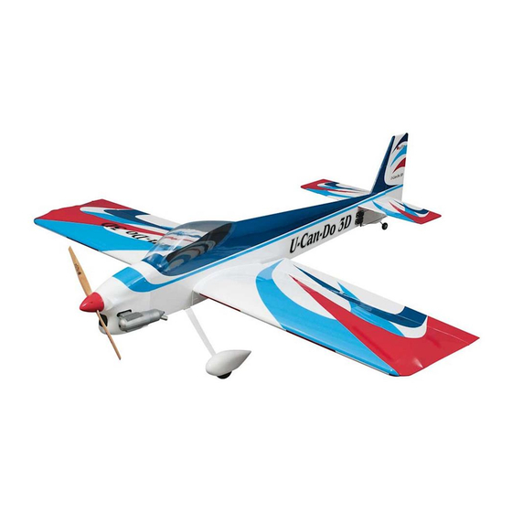
Wingspan: 82 in [2085mm]
Wing Area: 1772 sq in [114.3 dm
Weight: 12.5 – 13.5 lb [5600 – 6070g]
Wing Loading: 16.1 – 17.4 oz/sq ft [49 – 53 g/dm
Length: 84 in [2135mm]
Engine:
1.20 – 1.60 cu in [19.5 – 26.0cc] glow,
2.0 – 2.5 cu in [32.5 – 41.0cc] gas
Great Planes
®
Model Manufacturing Co. guarantees this kit to be free from defects in both material and workmanship at the date of purchase. This
warranty does not cover any component parts damaged by use or modification. In no case shall Great Planes' liability exceed the original cost of
the purchased kit. Further, Great Planes reserves the right to change or modify this warranty without notice.
In that Great Planes has no control over the final assembly or material used for final assembly, no liability shall be assumed nor accepted for any
damage resulting from the use by the user of the final user-assembled product. By the act of using the user-assembled product, the user accepts all
resulting liability.
If the buyer is not prepared to accept the liability associated with the use of this product, the buyer is advised to return this kit immediately
in new and unused condition to the place of purchase.
To make a warranty claim send the defective part or item to Hobby Services at the address below:
Include a letter stating your name, return shipping address, as much contact information as possible (daytime telephone number, fax number, e-mail
address), a detailed description of the problem and a photocopy of the purchase receipt. Upon receipt of the package the problem will be evaluated as
quickly as possible.
READ THROUGH THIS MANUAL BEFORE STARTING
CONSTRUCTION.
WARNINGS AND INSTRUCTIONS CONCERNING THE
ASSEMBLY AND USE OF THIS MODEL.
Entire Contents © Copyright 2005
INSTRUCTION MANUAL
2
]
2
]
3002 N. Apollo Dr., Suite 1
IT
CONTAINS
WARRANTY
Hobby Services
Champaign, IL 61822
USA
IMPORTANT
™
Champaign, IL
(217) 398-8970, Ext. 5
airsupport@greatplanes.com
GPMZ0199 for GPMA1271 V1.0
Advertisement
Table of Contents

Subscribe to Our Youtube Channel
Related Manuals for GREAT PLANES Giant U-Can-Do 3D


Summary of Contents for GREAT PLANES Giant U-Can-Do 3D
-
Page 1: Instruction Manual
Further, Great Planes reserves the right to change or modify this warranty without notice. In that Great Planes has no control over the final assembly or material used for final assembly, no liability shall be assumed nor accepted for any damage resulting from the use by the user of the final user-assembled product. -
Page 2: Table Of Contents
ORDERING REPLACEMENT PARTS.......6 For the latest technical updates or manual corrections to the METRIC CONVERSIONS ..........6 Giant U-CAN-DO 3D ARF, visit the web site listed below and PREPARATIONS..............6 select the Giant U-CAN-DO 3D ARF. If there is new Assemble the Pushrods..........6 technical information or changes to this model, a “tech... -
Page 3: Decisions You Must Make
Contact the AMA at the address or toll-free phone number that follows. Engine Notes: The Giant U-CAN-DO 3D ARF will hover on all of the recommended engines. The engines on the lower... -
Page 4: Covering Tools
Giant U-CAN-DO 3D ARF. IMPORTANT BUILDING NOTES Order numbers are provided in parentheses. ❏ Hook & Loop Velcro (GPMQ4480) ❏ 3' Medium fuel tubing (GPMQ4131) Sheet metal screws are designated by a number and a length. -
Page 5: Champaign, Il
If any parts are missing or are not of acceptable quality, or if you need assistance with assembly, contact Great Planes Product Support. When reporting defective or missing parts, use the part names exactly as they are written in the Kit Contents list on this page. -
Page 6: Ordering Replacement Parts
18" = 457.2 mm 1/4" = 6.4 mm 21" = 533.4 mm To locate a hobby dealer, visit the Great Planes web site at 3/8" = 9.5 mm 24" = 609.6 mm www.greatplanes.com . Choose “Where to Buy” at the bottom of 1/2"... -
Page 7: Assemble The Wing
❏ 2. Use denatured alcohol or other solvent to thoroughly clean one of the pushrods. Use coarse sandpaper to roughen the end of the pushrod where it is to be soldered. ❏ 7. Fit a silicone clevis retainer, 4-40 nut, another silicone clevis retainer and the clevis on the other end of the pushrod. - Page 8 ❏ ❏ ❏ ❏ 2. Use epoxy to glue in the two nylon wing dowels. 5. Test fit the aileron and flap to the wing with the hinges. Use a fine-point ballpoint pen to mark the aileron, flap and wing at the middle of each hinge. Note: Align the outer tip of the aileron with the outer tip of the wing.
-
Page 9: Hook Up The Flaps & Ailerons
❏ ❏ 4. Drill 1/16" [1.6mm] holes through the servo mounts for the servo screws. Add a few drops of thin CA to the holes and allow to fully harden. Mount the aileron and flap servos using the hardware that came with the servos. ❏... -
Page 10: Assemble The Fuselage
❏ ❏ ❏ 9.Turn on the transmitter and receiver to center the servo. 3. Use a #11 blade to cut between the false stab and the Place the servo arm on the servo. Note: For best performance stab fillet. 1-1/4" [32mm] long servo arms are recommended. ❏... -
Page 11: Mount The Landing Gear
you do plan on removing it, make sure to check the tightness of the screws often. ❏ 3. Use a #11 blade to remove the covering from the fin slot. ❏ 6. Check that the fin is perpendicular to the stab. If it’s not, then adjust the fin slot until the fin is perpendicular to the stab. - Page 12 ❏ ❏ 2. Remove steering arm and tailwheel from the wire. File 6. Mount the 3/16" x 2" [4.8 x 50mm] axles to the landing flat spots on the wire for the set screws. Note: DO NOT file gear with the 5/16-24 nuts. a flat spot for the wheel collar shown on the wire as this will weaken the wire at a high stress point.
-
Page 13: Mount The Engine
5. Use small clamps or another method to temporarily secure the engine to the mount with the backplate of the ❏ spinner 6" [152mm] from the firewall. Use the Great Planes 2. Drill a 1/16" [1.6mm] hole through the cowl and fuse Dead Center ™... - Page 14 ❏ 3. With your assistant holding the cowl in position, drill holes 2" [50mm] above and below the first screw. Secure this side of the cowl with two more #2 x 1/2" [13mm] screws and #2 washers. ❏ 7. Remount the cowl under the templates. Use a felt-tip pen to transfer the holes in the template onto the cowl.
-
Page 15: Install The Fuel Tank
Cut tank is pointing upward. the fuel line so that 4" [100mm] is protruding from the fuse side. Use a Great Planes Aluminum Fuel Line Plug (not included) to plug this fill line. ❏... -
Page 16: Final Assembly
line. Mark the hole locations on the elevators. Drill 1/8" FINAL ASSEMBLY [3mm] holes through the elevators at each of the marks. Mount the Tail Servos ❏ 5. Mount the control horns using the 4-40 x 3/4" [19mm] SHCS and the nylon backing plate on the top of the elevators. ❏... -
Page 17: Install The Throttle Servo, Receiver & Battery
Install the Throttle Servo, Receiver & Battery ❏ 9. Attach the 6-3/4" [172mm] pushrod to the outer holes on the rudder servo arm and the second to outer hole on the control horn. Adjust the length of the pushrod so that the rudder lines up with the fin. -
Page 18: Mount The Canopy
❏ ❏ 5. Mount the cowl, prop, muffler and spinner. 9. Mount the receiver on/off switch and charge jack. Mount the Canopy ❏ 6. Wrap the battery pack in 1/2" [13mm] of R/C foam rubber and use the Velcro ® strap to mount it to one of the battery/receiver trays. -
Page 19: Get The Model Ready To Fly
If, after you have become accustomed to the way the trims. If necessary, remove the servo arms from the servos Giant U-CAN-DO 3D ARF flies, you would like to change and reposition them so they are centered. Reinstall the the throws to suit your taste, that is fine. -
Page 20: Balance The Model Laterally
We keep a Great Planes Fingertip and other maneuvers. Prop Balancer (GPMQ5000) in our flight box. -
Page 21: Ground Check
Use a “chicken stick” or electric starter to start the engine. Ground Check Do not use your fingers to flip the propeller. Make certain the glow plug clip or connector is secure so that it will not pop If the engine is new, follow the engine manufacturer’s off or otherwise get into the running propeller. -
Page 22: Check List
4. I will operate my model using only radio control frequencies FLYING currently allowed by the Federal Communications Commission. The Giant U-CAN-DO 3D ARF is a great-flying model that flies smoothly and predictably. The Giant U-CAN-DO 3D ARF does not, however, possess the self-recovery... -
Page 23: Take Off
Take it easy with the Giant U-CAN-DO 3D ARF for the first few flights, gradually getting acquainted with it as you gain CAUTION (THIS APPLIES TO ALL R/C AIRPLANES): If, confidence. - Page 24 BUILDING NOTES Kit Purchased Date: _______________________ Date Construction Finished: _________________ Where Purchased:_________________________ Finished Weight: __________________________ Date Construction Started: __________________ Date of First Flight: ________________________ FLIGHT LOG...
Need help?
Do you have a question about the Giant U-Can-Do 3D and is the answer not in the manual?
Questions and answers