
Related Manuals for GLP Ipression XL


Summary of Contents for GLP Ipression XL
- Page 1 Instruction Manual from Software Version 1.09/0.3 (Manual Version 1.06) e-mail: service@glp.de Internet: http://www.glp.de...
- Page 2 For your notes: German Light Products GmbH (Manual Version 1.06) / from Software Version 1.09/0.3)
-
Page 3: Table Of Contents
Table of content Description of Device ......................4 Safety Instructions ........................5 Preparation and Installation....................6 Mounting ............................6 2.1.1 Mounting on the floor (upright) ..................7 2.1.2 Mounting in hanging position (Head down) ..............7 2.1.3 Mounting in sideway position ..................8 Securing the Device ........................9 Connections ..........................9 2.3.1 Power Supply .......................9... -
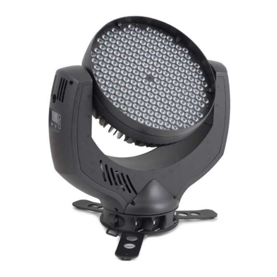
Page 4: Description Of Device
1 Description of Device 1. Moving head (actively and passively cooled) 2. Arm with various cooling vents 3. Tilt-lock to secure and lock the tilt movement see also 4. LCD-Display/Menu (data entry) 5. Base with various connectors and Camlock mounting system Safety eyelets b a se sid e 1... -
Page 5: Safety Instructions
Safety Instructions L is an advanced technology product. To guarantee smooth operation, it is necessary to follow the following instructions. The manufacturer of this device will not take responsibility of damages through any disregard of the information in this user manual. Warranty claims will also be cancelled in the event of the system casing being opened. -
Page 6: Preparation And Installation
10. Repair-, maintenance- and installation work should only be performed by qualified or GLP certified staff. You need to pay attention to the common rules of technology that are not explicit mentioned in this manual. 11. Use only original spare parts. Any structural modification on the system will terminate all warranty claims. -
Page 7: Mounting On The Floor (Upright)
2.1.1 Mounting on the floor (upright) To operate the N XL in an upright position, please use the dedicated floor-stand which ships with all original fixtures. The floor stand is mounted to the base of the fixture using the two Camlock quarter turn fasteners. -
Page 8: Mounting In Sideway Position
To operate the L in a sideways position, please use an additional mounting bar, available from GLP or one of their agents.. This mounting bar is fixed via the four camlock quick-release connectors. Two half-couplers or clamps are then used to hang the mounting bar. This technique is necessary to cope with the additional torque in this mounting position. -
Page 9: Securing The Device
2.2 Securing the Device Regardless of the mounting method of the L you'll have to use a secondary safety wire. This safety wire can be attached to the fixture by threading it through one of the two holes provided on the base of the fixture. Ensure that the safety wire is securely fastened through the fixture and the fixtures mounting support. -
Page 10: The Menu Field
The Menu Field You’ll find the control board on the side of the arm. It allows you to make all necessary adjustments of the . With the Mode-key you get into the main menu. Afterwards you can navigate through the menu with the Up/Down-keys. - Page 11 Tilt Offset Calibration for Tilt-Offset Clear Erase EEPROM memory EEPROM Diagnose Diagnose functions Pos Feed Pan Internal data and function diagnose Delta Anz Ti0-Int- Internal data and function diagnose PFC Voltage Show the present PFC voltage LED PWM Shows Dimmer-1-Software Version Vers 1 LED PWM Shows Dimmer-2-Software Version...
-
Page 12: Dmx Channel Sheet
Shutter Instantaneous value for shutter Blue Instantaneous value for blue Green Instantaneous value for green Instantaneous value for red Color Wheel Instantaneous value for Color Mixing unit Tilt Instantaneous value for Tilt movement Indicates the overall operation time of the Live time system Display... - Page 13 Channel Function Time and Value Color 10 - Mauve 80..87 50..57 31..34,5 Color 11 - Magenta 88..95 58..5F 35..37,5 Color 12 - Pink 96..103 60..67 38..40,5 White - CTO Color temperature 104..111 68..6F 41..43,5 3200K White Color temperature 112..119 70..77 44..46,5 5600K White - CTB...
- Page 14 Channel Function Time and Value TILT size / phase see also PAN 32..63 20..3F 13..25 PAN / TILT size / phase see also PAN 64..95 40..5F 26..37 PAN / TILT (inverse) size / phase see also PAN 96..127 60..7F 38..50 Circle size / phase see also PAN 128..159...
- Page 15 Channel Function Time and Value Color 09 - Lavender 72..79 48..4F 28..30,5 Color 10 - Mauve 80..87 50..57 31..34,5 Color 11 - Magenta 88..95 58..5F 35..37,5 Color 12 - Pink 96..103 60..67 38..40,5 White - CTO Color temperature 104..111 68..6F 41..43,5 3200K White...
- Page 16 Channel Function Time and Value 11) Shutter Shutter closed 0..15 00..0F 0..5,5 Random Pulse effect slow - fast 16..47 10..2F 6..18,5 Up-dimming then Shutter closing slow - fast 48..79 30..4F 19..31,5 (random patterns) Shutter open then down-dimming slow - fast 80..111 50..6F 32..43...
-
Page 17: Maintaining And Cleaning The I M P R E S S I O N X L
c) Standard Mode (Hold down the ENTER- button during power ON) After switching on the fixture, the DMX start address will be set to [001]. All other settings will remain unchanged. Additional Display Indications As a default you'll find the following additional information in the first row of the LCD display: XX/X/XX 06 = 600Hz / 12 = 1200Hz N = Normal Mode / C = Compressed Mode / H = High Res. -
Page 18: Technical Specifications
Cleaning of fans and air channels monthly vacuum cleaner, airbrush, etc. Attention: • Never let optical parts come into contact with oil or fat. • Before running the fixture wait until all parts are touch dry. • Never touch lenses with bare fingers. 6 Technical Specifications Power supply Power consumption... - Page 19 Scattering light aperture Shutter / Dimmer (8/16 Bit) Strobe- Effect with variable speed between 1 - 10 flashes per second, Random-Strobe, Pulse- Effects Continuous Dimmer 0 - 100% DMX Control Standard USITT DMX-512, 3/5 pole XLR; [+] = Pin 3 [-] = Pin 2 [Ground] = Pin 1.
-
Page 20: Index
7 Index Mounting in hanging Position ......7 Mounting in sidewise Position ......8 BGV C1............6 Mounting on the Floor ........6 Circumference ..........17 Normal-Mode ..........12 Cleaning............16 Compress-Mode ........14, 15 Optical parts ..........17 Description of Device ........4 DIN VDE 0711-217 .......... - Page 21 German Light Products GmbH (Manual Version 1.06) / from Software Version 1.09/0.3)
Need help?
Do you have a question about the Ipression XL and is the answer not in the manual?
Questions and answers