
Related Manuals for GLP impression rgb 120 rz


Summary of Contents for GLP impression rgb 120 rz
- Page 1 1.00/30 (Instruction version 1.0) e-mail: service@glp.de Internet: http://www.glp.de...
- Page 2 Notes: German Light Products GmbH (Instruction version 1.0) / from software version 1.00/30)
-
Page 3: Table Of Contents
Table of content Description of Device....................4 1.1 Safety Instructions .................... 5 Preparation and Installation ................... 6 2.1 Mounting ......................6 2.1.1 Mounting on the Floor (Upright)............. 7 2.1.2 Mounting in hanging Position (Head first)..........7 2.1.3 Mounting in sidewise Position ............... 8 2.2 Secure the Device..................... -
Page 4: Description Of Device
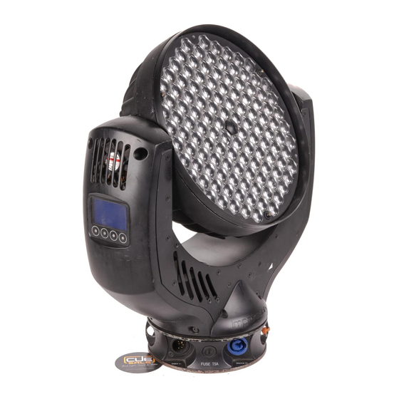
1 Description of Device 1. Moving head (actively and passively cooled) 2. Arm with various cooling vents 3. LCD-Display/Menu (data entry) 4. Base with various connectors and Camlock mounting system base side 1 5. Power On/Off 6. DMX- Output (3 pole) 7. -
Page 5: Safety Instructions
Safety cables or clamps/hooks can increase the risk of an accident. 8. Repair-, maintenance- and installation work shall be done by qualified or GLP certified staff only. You need to pay attention to the common rules of technology that are not explicit mentioned in this manual. -
Page 6: Preparation And Installation
2 Preparation and Installation 2.1 Mounting N is fully operational whether it hangs or is mounted to the wall. It can also be operated while standing on the floor. Keep a safety distance of 0.5 m towards any easily inflammable materials (decoration etc.). Pay attention to the regulations of: BGV C1 (former VBG 70) and DIN VDE 0711-217. -
Page 7: Mounting On The Floor (Upright)
1x M10 (length max.16mm) 2x Camlock quick release fasteners front side of the fixture 2.1.1 Mounting on the Floor (Upright) To operate the N in an upright position, please use the dedicated tripod which is mounted to the bottom side of the system. It is fixed with fasteners called Camlock quick-release connectors. -
Page 8: Mounting In Sidewise Position
M10x16 2.1.3 Mounting in sidewise Position To operate the N in a sidewise position, please use an addition mounting bar. Also this is fixed by two Camlock quick-release connectors. Two half-couplers (clamps) are now used to mount the system to a standard truss bar. This technique is necessary to cope with the torque which accrues in this mounting position. -
Page 9: Secure The Device
without mounting bar 2.2 Secure the Device Regardless of the mounting method of the N you'll have to use a stipulated safety wire. Therefore you have to pull the safety wire through to two provided holes on the bottom side of the system and connect it with the truss- support. -
Page 10: The Menu Field
3 The Menu Field You’ll find the control board on the side part of the arm. It allows you to make all necessary adjustments of the . With the Mode-key you get into the main menu. Afterwards you can navigate through the menu with the Up/Down-keys. - Page 11 Clear Erase EEPROM memory EEPROM Diagnose Diagnose functions Pos Feed Internal data and function diagnose Pan Delta Anz Ti0- Internal data and function diagnose Int-Err Show the present PFC voltage Voltage Pos Feed Internal data and function diagnose Tilt Delta Temperature Indicates the arm temperature Temperature...
-
Page 12: Dmx Channel Selection (Dmx Protocol)
Self test Performs an automatic self-test Live time Indicates the overall operation time of the system Display Adjust the display Blackout ON/OFF: Display OFF Select DMX Please select the desired DMX Mode Mode Fixture works in "Compressed" mode see also Compressed section 4 below Fixture works in "Normal"... - Page 13 Channel Function Time and Value Rainbow Effect Stop Rainbow Effect slow - fast 129..223 81..DF 51..88 Rainbow Effect, random colors slow - fast 224.255 E=..FF 89..100 6) Red Color mixing system - Red 0 - 100% 0..255 00..FF 0..100 7) Green Color mixing system - Green 0 - 100% 0..255...
- Page 14 Channel Function Time and Value Pan/Tilt Pan/Tilt slow – fast Pan Min. 660° = 200s 16..255 10..FF 7..100 Use this channel 14) also for the speed Pan Max. 660° = 3,2s of the movements (channel 13). Tilt Min. 300° = 110s Tilt Max.
- Page 15 Channel Function Time and Value White - CTB Color temperature 120..127 78..7F 47..49,5 7200K Rainbow Effect Stop Rainbow Effect slow - fast 129..223 81..DF 51..88 Rainbow Effect, random colors slow - fast 224.255 E0..FF 89..100 6) Red Color mixing system - Red 0 - 100% 0..255 00..FF...
- Page 16 Channel Function Time and Value Up-dimming then down-dimming slow - fast 112..143 70..8F 44..56 (random patterns) Strobe effect pause 5s to 1s 144..199 A0..C7 57..77 Strobe effect, slow - fast 1 Hz .. 10 Hz 200..239 C8..EF 78..94 Shutter open 240...249 F0..F9 95..97,5 RESET Min.
-
Page 17: Maintaining And Cleaning The
Additional Display Indications As a default you'll find the following additional information in the first row of the LCD display: XX/X/XX 06 = 600Hz / 12 = 1200Hz N = Normal Mode / C = Compressed Mode / H = High Res. Mode N = Tilt normal / I = Tilt inverted N = Pan normal / I = Pan inverted 5 Maintaining and Cleaning the... -
Page 18: Technical Specifications
6 Technical Specifications Power supply Power consumption 350 VA (Watt) Power Input ~100-240 V AC, 50-60 Hz (wide range input) Fuse protection Micro-fuse 5x20 mm, T5A Operational Parameters Max. Ambient 45°C (integrated overheating switch) Temperature Mounting Position Any (see chapter mounting) Lighting System - Additive Color mixing LED Type 120x Rebel High-power- LEDs... -
Page 19: Index
7 Index Mounting in hanging Position ......8 Mounting in sidewise Position ......9 Angel of reflected beam ......20 Mounting on the Floor ........8 BGV C1............7 Normal-Mode ..........13 Camlock............8 Optical parts ..........19 Circumference..........18 Cleaning............ -
Page 20: Glp German Light Products Gmbh (Instruction Version 1.0) / From Software Version 1.00/30)
German Light Products GmbH (Instruction version 1.0) / from software version 1.00/30)
Need help?
Do you have a question about the impression rgb 120 rz and is the answer not in the manual?
Questions and answers