
Related Manuals for GLP IMPRESSION WWC STATIC


Summary of Contents for GLP IMPRESSION WWC STATIC
- Page 1 & & & from software version 1.00/30 (Instruction version 1.00) e-mail: service@glp.de Internet: http://www.glp.de...
- Page 2 & & & Preface This manual serves for both systems the C as well as the . The two systems differ from each other only by the number of cold- respectively warm- white LEDs. WWC version: 30x LEDs cold white, 60x LEDs warm white CCW version: 60x LEDs cold white, 30x LEDs warm white Notes: German Light Products GmbH...
-
Page 3: Table Of Contents
& & & Table of content Description of Device....................4 1.1 Safety Instructions .................... 5 Preparation and Installation ................... 6 2.1 Mounting ......................6 2.1.1 Mounting on the Floor (Upright) ............7 2.1.2 Mounting in hanging Position (Head first) ..........7 2.1.3 Mounting in sidewise Position .............. -
Page 4: Description Of Device
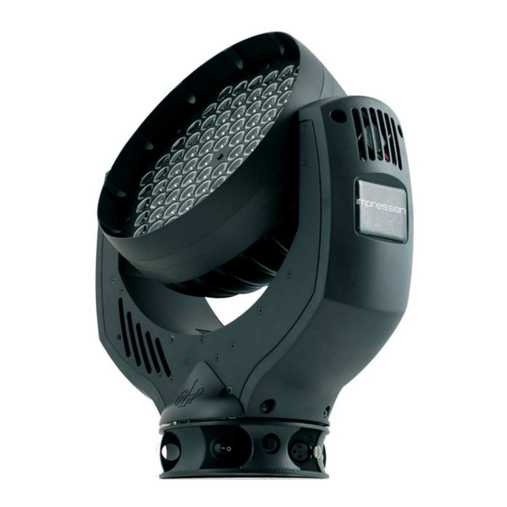
& & & 1 Description of Device 1. Moving head (actively and passively cooled) 2. Arm with various cooling vents 3. LCD-Display/Menu (data entry) 4. Base with various connectors and Camlock mounting system b a se sid e 1 5. Power On/Off 6. -
Page 5: Safety Instructions
Safety cables or clamps/hooks can increase the risk of an accident. 8. Repair-, maintenance- and installation work shall be done by qualified or GLP certified staff only. You need to pay attention to the common rules of technology that are not explicit mentioned in this manual. -
Page 6: Preparation And Installation
& & & 2 Preparation and Installation 2.1 Mounting N is fully operational whether it hangs or is mounted to the wall. It can also be operated while standing on the floor. Keep a safety distance of 0.5 m towards any easily inflammable materials (decoration etc.). Pay attention to the regulations of: BGV C1 (former VBG 70) and DIN VDE 0711-217. -
Page 7: Mounting On The Floor (Upright)
& & & 1x M10 (length max.16mm) 2x Camlock quick release fasteners front side of the fixture 2.1.1 Mounting on the Floor (Upright) To operate the N in an upright position, please use the dedicated tripod which is mounted to the bottom side of the system. It is fixed with fasteners called Camlock quick-release connectors. -
Page 8: Mounting In Sidewise Position
& & & M10x16 2.1.3 Mounting in sidewise Position To operate the N in a sidewise position, please use an addition mounting bar. Also this is fixed by two Camlock quick-release connectors. Two half-couplers (clamps) are now used to mount the system to a standard truss bar. -
Page 9: Secure The Device
& & & without mounting bar 2.2 Secure the Device Regardless of the mounting method of the N you'll have to use a stipulated safety wire. Therefore you have to pull the safety wire through to two provided holes on the bottom side of the system and connect it with the truss- support. -
Page 10: The Menu Field
& & & 3 The Menu Field You’ll find the control board on the side part of the arm. It allows you to make all necessary adjustments of the . With the Mode- key you get into the main menu. Afterwards you can navigate through the menu with the Up/Down-keys. -
Page 11: Dmx Channel Selection (Dmx Protocol)
& & & DMX input Indicates the presently received DMX signal per Monitor DMX channel Special Current value for Special Dimmer Current value for Dimmer Shutter Current value for Shutter Current value for 1/3 White, 30x LEDs (either warm- 1/3 White or cold white depending on the system) Current value for 2/3 White, 60x LEDs (either warm- 2/3 White... - Page 12 & & & Compress-Mode 4 DMX channels Channel Function Time and Value 1) White 2/3 White Color, 60x LEDs (either warm- 0 - 100% 0..255 00..FF 0..100 or cold white depending on the system) 2) White 1/3 White Color, 30x LEDs (either warm- 0 - 100% 0..255 00..FF...
- Page 13 & & & Locking and unlocking the Control Panel Please lock and unlock the control panel by pressing the menu keys MODE & ENTER & UP at the same time. Additional features during switching-ON the system a) 1200Hz Mode (Hold down the UP- button during power ON) After switching ON the system the LEDs will be operated with a Pulse Width Modulation (PWM) of 1200Hz.
-
Page 14: Maintaining And Cleaning The I M P R E S S I O N
& & & 5 Maintaining and Cleaning the N is a system of very low maintenance. It is only necessary to clean the air in- and outlets as well as the optical LED lenses from time to time. For a safe operation it is absolutely essential that the fixture is kept clean and that dust, dirt and smoke-fluid residues must not built up on or within the fixture. -
Page 15: Technical Specifications
& & & 6 Technical Specifications Power supply Power consumption 350 VA (Watt) Power Input ~100-240 V AC, 50-60 Hz (wide range input) Fuse protection Micro-fuse 5x20 mm, T4A Operational Parameters Max. Ambient 45° C (integrated overheating switch) Temperature Mounting Position Any (see chapter mounting) Lighting System - Additive Color mixing (8/16 Bit) LED Type... -
Page 16: Index
& & & 7 Index 1200Hz Mode ..........13 Maintenance ..........14 Menu Field ............ 10 Micro-fuse ............9 600Hz Mode ..........13 Mode-key ............10 Mounting ............6 Mounting in hanging Position ......7 BGI 810-3 ............9 Mounting in sidewise Position ......8 BGV C1............ - Page 17 & & & German Light Products GmbH (Instruction version 1.00) / from software version 1.00/30)
Need help?
Do you have a question about the IMPRESSION WWC STATIC and is the answer not in the manual?
Questions and answers